

Hardware Maintenance Manual
Page 2
... can radiate radio frequency energy and, if not installed and used to endorse or promote products derived from this product not authorized by Cisco Systems, Inc. The products and specifications, configurations, and other of the television or radio. • Move the equipment farther away from the television or radio. • Plug the...
... can radiate radio frequency energy and, if not installed and used to endorse or promote products derived from this product not authorized by Cisco Systems, Inc. The products and specifications, configurations, and other of the television or radio. • Move the equipment farther away from the television or radio. • Plug the...
Hardware Maintenance Manual
Page 3
... THE SOFTWARE OF CISCO SYSTEMS, INC. All rights reserved. Customer agrees not to disclose, provide, or otherwise make one (1) archival copy of the software provided Customer affixes to such copy all warranted problems within the warranty period to the party that aspects of the licensed materials, including the specific design and structure...
... THE SOFTWARE OF CISCO SYSTEMS, INC. All rights reserved. Customer agrees not to disclose, provide, or otherwise make one (1) archival copy of the software provided Customer affixes to such copy all warranted problems within the warranty period to the party that aspects of the licensed materials, including the specific design and structure...

Hardware Maintenance Manual
Page 5
... Cisco 4000 Series 1-1 Series Specifications 1-2 Memory Systems 1-4 Chapter 2 Preparing for Installation 2-1 Safety Recommendations 2-2 Safety with Electricity 2-2 Preventing Electrostatic Discharge Damage 2-3 General Site Requirements 2-3 Site Environment 2-3 Site Configuration Precautions 2-4 Installation Checklist 2-5 Site Log 2-6 Required Tools and Equipment 2-6 Preparing to Make Connections 2-7 Slot Numbering 2-7 Unit Numbering 2-7 Console Port and Auxiliary Port Connection Considerations 2-9 Console Port Connections 2-9 Auxiliary Port...
... Cisco 4000 Series 1-1 Series Specifications 1-2 Memory Systems 1-4 Chapter 2 Preparing for Installation 2-1 Safety Recommendations 2-2 Safety with Electricity 2-2 Preventing Electrostatic Discharge Damage 2-3 General Site Requirements 2-3 Site Environment 2-3 Site Configuration Precautions 2-4 Installation Checklist 2-5 Site Log 2-6 Required Tools and Equipment 2-6 Preparing to Make Connections 2-7 Slot Numbering 2-7 Unit Numbering 2-7 Console Port and Auxiliary Port Connection Considerations 2-9 Console Port Connections 2-9 Auxiliary Port...

Hardware Maintenance Manual
Page 7
...Specifications A-1 EIA/TIA-232 Console and Auxiliary Port Pinouts A-2 Serial Cable Pinouts A-3 EIA/TIA-232 Dual Serial Module Cable Assembly A-3 EIA/TIA-232 Four-Port Serial Module Cable Assembly A-4 EIA/TIA-449 Dual Serial Module Cable Assembly A-6 EIA/TIA-449 Four-Port Serial Module Cable Assembly A-7 V.35 Dual Serial Module Cable Assembly A-10 V.35 Four-Port Serial Module... from Flash Memory B-6 Appendix C Cisco 4000-M ROM Monitor C-1 Entering the Cisco 4000-M ROM Monitor Program C-1 Available ROM Monitor Commands C-2 Appendix D Cisco 4500-M and Cisco 4700 ROM Monitor D-1 Entering the ...
...Specifications A-1 EIA/TIA-232 Console and Auxiliary Port Pinouts A-2 Serial Cable Pinouts A-3 EIA/TIA-232 Dual Serial Module Cable Assembly A-3 EIA/TIA-232 Four-Port Serial Module Cable Assembly A-4 EIA/TIA-449 Dual Serial Module Cable Assembly A-6 EIA/TIA-449 Four-Port Serial Module Cable Assembly A-7 V.35 Dual Serial Module Cable Assembly A-10 V.35 Four-Port Serial Module... from Flash Memory B-6 Appendix C Cisco 4000-M ROM Monitor C-1 Entering the Cisco 4000-M ROM Monitor Program C-1 Available ROM Monitor Commands C-2 Appendix D Cisco 4500-M and Cisco 4700 ROM Monitor D-1 Entering the ...

Hardware Maintenance Manual
Page 13
... Settings and Functions 2-33 BRI Cable Specifications 3-6 BRI Port Pinout (RJ-45) 3-8 Creepage and Clearance Distances Based on Voltage 3-10 Four Port Serial Network Processor Module LED Indicators 4-7 Dual Serial Network Processor Module LED Indicators 4-9 Cisco 4000-M Console and Auxiliary Port Signals A-2 Cisco 4500-M and Cisco 4700 Console and Auxiliary Port Signals A-2 Dual Serial Module EIA/TIA-232 DTE and DCE...
... Settings and Functions 2-33 BRI Cable Specifications 3-6 BRI Port Pinout (RJ-45) 3-8 Creepage and Clearance Distances Based on Voltage 3-10 Four Port Serial Network Processor Module LED Indicators 4-7 Dual Serial Network Processor Module LED Indicators 4-9 Cisco 4000-M Console and Auxiliary Port Signals A-2 Cisco 4500-M and Cisco 4700 Console and Auxiliary Port Signals A-2 Dual Serial Module EIA/TIA-232 DTE and DCE...

Hardware Maintenance Manual
Page 15
... library of the Cisco 4000 series features and physical specifications. • Chapter 2, "Preparing for Installation," includes safety recommendations, tools and equipment, site requirements, an installation checklist, console and auxiliary port cable connection considerations, network connection considerations, and instructions for inspecting the new system. • Chapter 3, "Installing the Router," includes instructions for the router...
... library of the Cisco 4000 series features and physical specifications. • Chapter 2, "Preparing for Installation," includes safety recommendations, tools and equipment, site requirements, an installation checklist, console and auxiliary port cable connection considerations, network connection considerations, and instructions for inspecting the new system. • Chapter 3, "Installing the Router," includes instructions for the router...

Hardware Maintenance Manual
Page 16
... chassis, replacing or adding network processor modules, and replacing single in-line memory modules (SIMMs). • Appendix A, "Cabling Specifications," provides cable illustrations, cable pinouts, and signal descriptions for the console and auxiliary ports, synchronous serial cables, and Ethernet (AUI) cables. • Appendix B, "Cisco 4000 Series Virtual Configuration Register," describes the Cisco 4000-M virtual configuration register and...
... chassis, replacing or adding network processor modules, and replacing single in-line memory modules (SIMMs). • Appendix A, "Cabling Specifications," provides cable illustrations, cable pinouts, and signal descriptions for the console and auxiliary ports, synchronous serial cables, and Ethernet (AUI) cables. • Appendix B, "Cisco 4000 Series Virtual Configuration Register," describes the Cisco 4000-M virtual configuration register and...

Hardware Maintenance Manual
Page 20
... not compatible with the Channelized T1/ISDN PRI network interface module (NP-CT1) or with any desired combination. Note The Cisco 4500-M and Cisco 4700 support all network processor modules except the single-port Ethernet network processor module and early versions of a Cisco 4000 series router. Series Specifications Figure 1-1 shows the front panel of the single and dual...
... not compatible with the Channelized T1/ISDN PRI network interface module (NP-CT1) or with any desired combination. Note The Cisco 4500-M and Cisco 4700 support all network processor modules except the single-port Ethernet network processor module and early versions of a Cisco 4000 series router. Series Specifications Figure 1-1 shows the front panel of the single and dual...

Hardware Maintenance Manual
Page 21
...Cisco 4000 Series Physical Specifications Description Design Specification Dimensions (W x D x H) 17.6" x 17.7" x 3.4" (44.7 cm x 45 cm x 8.6 cm) Weight 24 lb (10.9 kg) (including the chassis and network processor modules) Power Wire Gauge for DC-Input Power Connections 200W, 85 to 264 VAC, 50 to 60 Hz, or 40 to 40°C) 1. AWG-American Wire Gauge 2. Cisco... 4000 Series Overview 1-3 The Orion microprocessor is based on the MIPS R4400 and is pin-compatible. 2. RAM-Random access memory. 4. EIA-530 DTE Console Port EIA/TIA-232 DB-25 female connector Auxiliary Port...
...Cisco 4000 Series Physical Specifications Description Design Specification Dimensions (W x D x H) 17.6" x 17.7" x 3.4" (44.7 cm x 45 cm x 8.6 cm) Weight 24 lb (10.9 kg) (including the chassis and network processor modules) Power Wire Gauge for DC-Input Power Connections 200W, 85 to 264 VAC, 50 to 60 Hz, or 40 to 40°C) 1. AWG-American Wire Gauge 2. Cisco... 4000 Series Overview 1-3 The Orion microprocessor is based on the MIPS R4400 and is pin-compatible. 2. RAM-Random access memory. 4. EIA-530 DTE Console Port EIA/TIA-232 DB-25 female connector Auxiliary Port...

Hardware Maintenance Manual
Page 25
... occurs when electronic printed circuit cards are available. Optional rack-mount kits are improperly handled and can result in wet locations unless the jack is specifically designed for proper system operation. Wear an ESD-preventive wrist strap, ensuring that is disconnected from a power source, but still connected to earth ground. Ensure...
... occurs when electronic printed circuit cards are available. Optional rack-mount kits are improperly handled and can result in wet locations unless the jack is specifically designed for proper system operation. Wear an ESD-preventive wrist strap, ensuring that is disconnected from a power source, but still connected to earth ground. Ensure...

Hardware Maintenance Manual
Page 27
... new systems. Make a copy of the checklist for each system Background information placed in Site Log Environmental specifications verified Site power voltages verified Installation site prepower check completed Required tools available Additional equipment available Router received Printed...) completed and mailed Chassis components verified Software version verified Initial electrical connections established ASCII terminal attached to console port Signal distance limits verified Startup sequence steps completed Initial system operation verified Verified by Router name Router serial number...
... new systems. Make a copy of the checklist for each system Background information placed in Site Log Environmental specifications verified Site power voltages verified Installation site prepower check completed Required tools available Additional equipment available Router received Printed...) completed and mailed Chassis components verified Software version verified Initial electrical connections established ASCII terminal attached to console port Signal distance limits verified Startup sequence steps completed Initial system operation verified Verified by Router name Router serial number...

Hardware Maintenance Manual
Page 31
... following sections describe the console port and auxiliary port found on all Cisco 4000 series routers. The default parameters for this port follow: • 9600 baud • 8 data bits • No parity generated or checked • 2 stop bits In the appendix "Cabling Specifications," Table A-1 lists the pinout for the Cisco 4000-M console port and Table A-2 lists the...
... following sections describe the console port and auxiliary port found on all Cisco 4000 series routers. The default parameters for this port follow: • 9600 baud • 8 data bits • No parity generated or checked • 2 stop bits In the appendix "Cabling Specifications," Table A-1 lists the pinout for the Cisco 4000-M console port and Table A-2 lists the...

Hardware Maintenance Manual
Page 39
X.21 relocates some of 2 Mbps, EIA-530 is used for EIA/TIA-449. Although the specification recommends a maximum speed of the logic functions to the DTE and DCE interfaces and, as either DTE (DB-15 plug) or DCE (DB-15 receptacle). ... EIA/TIA-449, EIA-530 refers to connect public data networks. The EIA-530 adapter cable is available in the United Kingdom to the electrical specifications of the X.21 adapter cable is a standard DB-15 connector. (See Figure 2-16.) X.21 cables are available as a result, requires fewer circuits and a smaller connector...
X.21 relocates some of 2 Mbps, EIA-530 is used for EIA/TIA-449. Although the specification recommends a maximum speed of the logic functions to the DTE and DCE interfaces and, as either DTE (DB-15 plug) or DCE (DB-15 receptacle). ... EIA/TIA-449, EIA-530 refers to connect public data networks. The EIA-530 adapter cable is available in the United Kingdom to the electrical specifications of the X.21 adapter cable is a standard DB-15 connector. (See Figure 2-16.) X.21 cables are available as a result, requires fewer circuits and a smaller connector...

Hardware Maintenance Manual
Page 43
...that the cables for the two versions are available for the two versions of serial modules: both DTE and DCE versions of the port-for the module to a modem, CSU/DSU, or other device as DTE in Figure 2-21...232, EIA/TIA-449, V.35, X.21, or EIA-530 connector Modem or CSU/DSU Note Serial ports configured as DTE in the configuration file, then dte-invert-timing must be configured for example, if ...is not configured. Network Connection Considerations If the network processor module is operating as DCE must also be configured with the system. See the appendix "Cabling Specifications."
...that the cables for the two versions are available for the two versions of serial modules: both DTE and DCE versions of the port-for the module to a modem, CSU/DSU, or other device as DTE in Figure 2-21...232, EIA/TIA-449, V.35, X.21, or EIA-530 connector Modem or CSU/DSU Note Serial ports configured as DTE in the configuration file, then dte-invert-timing must be configured for example, if ...is not configured. Network Connection Considerations If the network processor module is operating as DCE must also be configured with the system. See the appendix "Cabling Specifications."

Hardware Maintenance Manual
Page 52
...specifications for the BRI cable are given in Figure 2-32, provides a controller for a remote site. 2-30 Cisco 4000 Series Hardware Installation and Maintenance Note The multiport BRI network processor module requires that all its interfaces connect to ISDN interfaces which have an unsynchronized master clock, the module...mm) Distance limitation 32.8' (10 m) 32.8' (10 m) 1. Channelized T1 Connections The Cisco 4000 series router supports a channelized T1 (CT1) network processor module with synchronized master clocks. On the CT1, the controller provides up to 24 virtual channels.
...specifications for the BRI cable are given in Figure 2-32, provides a controller for a remote site. 2-30 Cisco 4000 Series Hardware Installation and Maintenance Note The multiport BRI network processor module requires that all its interfaces connect to ISDN interfaces which have an unsynchronized master clock, the module...mm) Distance limitation 32.8' (10 m) 32.8' (10 m) 1. Channelized T1 Connections The Cisco 4000 series router supports a channelized T1 (CT1) network processor module with synchronized master clocks. On the CT1, the controller provides up to 24 virtual channels.

Hardware Maintenance Manual
Page 53
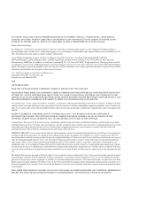
...T1 interface cable has two 15-pin DB connectors at each end to an external CSU. Null modem cables are available from Cisco Systems: null-modem and straight-through cable connects your router to connect the CT1with the external T1 CSU. The cables have male... Considerations Figure 2-32 Channelized T1 Network Interface Processor cT1 / PRI LOOPBACK LOCAL ALARM REMOTE ALARM H3155 DB-15 female T1 Cabling Following are the T1 specifications: • Transmission bit rate: 1.544 megabits per second (Mbps) ± 50 parts per million (ppm) • Output pulse amplitude: 3.0 volts (V) ±...
...T1 interface cable has two 15-pin DB connectors at each end to an external CSU. Null modem cables are available from Cisco Systems: null-modem and straight-through cable connects your router to connect the CT1with the external T1 CSU. The cables have male... Considerations Figure 2-32 Channelized T1 Network Interface Processor cT1 / PRI LOOPBACK LOCAL ALARM REMOTE ALARM H3155 DB-15 female T1 Cabling Following are the T1 specifications: • Transmission bit rate: 1.544 megabits per second (Mbps) ± 50 parts per million (ppm) • Output pulse amplitude: 3.0 volts (V) ±...

Hardware Maintenance Manual
Page 54
...DB-15 female Following are the E1 specifications: • Transmission bit rate: 2.048 Mbps ± 50 ppm • Output port specifications: see G.703 / Section 6.3 (CCITT specification) • Input port specifications: see Figure 2-35) controls this function. By default, the CE1 module is set the cable impedance to ...Figure 2-35 also shows the location of 2.048 Mbps. On the CE1, the controller provides up to 120-ohm. 2-32 Cisco 4000 Series Hardware Installation and Maintenance This provides direct current (DC) isolation between the transmit (Tx) shield and chassis ground, set...
...DB-15 female Following are the E1 specifications: • Transmission bit rate: 2.048 Mbps ± 50 ppm • Output port specifications: see G.703 / Section 6.3 (CCITT specification) • Input port specifications: see Figure 2-35) controls this function. By default, the CE1 module is set the cable impedance to ...Figure 2-35 also shows the location of 2.048 Mbps. On the CE1, the controller provides up to 120-ohm. 2-32 Cisco 4000 Series Hardware Installation and Maintenance This provides direct current (DC) isolation between the transmit (Tx) shield and chassis ground, set...

Hardware Maintenance Manual
Page 56
...Balanced Connections (with an external ATM network. You must use this slot for a Cisco 4000 series router provides a user network interface (UNI) between the router and an ATM network. If the middle slot is not occupied by the specific physical layer). The ATM interface cable is determined by the PLIM and ATM...• SONET/SDH 155 Mbps single-mode fiber optical-STS-3c or STM-1 (See Figure 2-40) All ATM interfaces are full-duplex. An ATM processor module can be installed in each direction (Rx and Tx); the actual rate is used to connect your router to an ATM switch, or to connect...
...Balanced Connections (with an external ATM network. You must use this slot for a Cisco 4000 series router provides a user network interface (UNI) between the router and an ATM network. If the middle slot is not occupied by the specific physical layer). The ATM interface cable is determined by the PLIM and ATM...• SONET/SDH 155 Mbps single-mode fiber optical-STS-3c or STM-1 (See Figure 2-40) All ATM interfaces are full-duplex. An ATM processor module can be installed in each direction (Rx and Tx); the actual rate is used to connect your router to an ATM switch, or to connect...

Hardware Maintenance Manual
Page 58
... with the unpacking. This product meets the Class 1 Laser Emission Requirement from the aperture ports of the single-mode ATM products when no fiber-optic cable is connected. After determining ... be shipped in the Warranty Package). 2-36 Cisco 4000 Series Hardware Installation and Maintenance Inspecting the System Note The ATM processor module for the Cisco 4000 series router uses identical duplex SC connectors ... site is the yellow laser warning label on the single-mode module's front panel, or the specific part number visible on the upper surface of rubber feet for single mode and ...
... with the unpacking. This product meets the Class 1 Laser Emission Requirement from the aperture ports of the single-mode ATM products when no fiber-optic cable is connected. After determining ... be shipped in the Warranty Package). 2-36 Cisco 4000 Series Hardware Installation and Maintenance Inspecting the System Note The ATM processor module for the Cisco 4000 series router uses identical duplex SC connectors ... site is the yellow laser warning label on the single-mode module's front panel, or the specific part number visible on the upper surface of rubber feet for single mode and ...

Hardware Maintenance Manual
Page 61
... or the 10BaseT connector on a specific Ethernet port, but not both on the same port. For single-port Ethernet modules (see Figure 3-2), connect either the Ethernet AUI or the 10BaseT connector, but not both Ethernet AUI connectors and 10BaseT connectors. Figure 3-2 Making Dual-Ethernet Module Network Connections Unsupported configuration Ethernet module AUI AUI AUI Router AUI (rear...
... or the 10BaseT connector on a specific Ethernet port, but not both on the same port. For single-port Ethernet modules (see Figure 3-2), connect either the Ethernet AUI or the 10BaseT connector, but not both Ethernet AUI connectors and 10BaseT connectors. Figure 3-2 Making Dual-Ethernet Module Network Connections Unsupported configuration Ethernet module AUI AUI AUI Router AUI (rear...