
Hardware Maintenance Manual
Page 5
TABLE OF CONTENTS About This Manual xv Document Objectives xv Audience xv Document Organization xv Document Conventions xvi Chapter 1 Cisco 4000 Series Overview 1-1 External Differences in Models of the Cisco 4000 Series 1-1 Series Specifications 1-2 Memory Systems 1-4 Chapter 2 Preparing for Installation 2-1 Safety Recommendations 2-2 Safety with Electricity 2-2 Preventing Electrostatic Discharge Damage 2-3 General Site Requirements 2-3 Site Environment...
TABLE OF CONTENTS About This Manual xv Document Objectives xv Audience xv Document Organization xv Document Conventions xvi Chapter 1 Cisco 4000 Series Overview 1-1 External Differences in Models of the Cisco 4000 Series 1-1 Series Specifications 1-2 Memory Systems 1-4 Chapter 2 Preparing for Installation 2-1 Safety Recommendations 2-2 Safety with Electricity 2-2 Preventing Electrostatic Discharge Damage 2-3 General Site Requirements 2-3 Site Environment...

Hardware Maintenance Manual
Page 6
... Tray 5-2 Removing Network Processor Modules 5-4 Memory Replacement Procedures 5-6 Replacing Main Memory SIMMs 5-8 Removing Main Memory SIMMS 5-9 Installing Main Memory SIMMs 5-11 Replacing Shared-Memory SIMMs 5-13 Inserting Shared-Memory SIMMs 5-14 Removing the Cisco 4500-M and Cisco 4700 Boot Helper Flash Memory SIMM 5-16 Installing Flash-Memory SIMMs 5-17 Replacing Boot ROMs in the Cisco 4000-M 5-19 Replacing Network Processor Modules...
... Tray 5-2 Removing Network Processor Modules 5-4 Memory Replacement Procedures 5-6 Replacing Main Memory SIMMs 5-8 Removing Main Memory SIMMS 5-9 Installing Main Memory SIMMs 5-11 Replacing Shared-Memory SIMMs 5-13 Inserting Shared-Memory SIMMs 5-14 Removing the Cisco 4500-M and Cisco 4700 Boot Helper Flash Memory SIMM 5-16 Installing Flash-Memory SIMMs 5-17 Replacing Boot ROMs in the Cisco 4000-M 5-19 Replacing Network Processor Modules...

Hardware Maintenance Manual
Page 7
... B-1 Virtual Configuration Register Settings B-1 Changing Configuration Register Settings B-2 Configuring the Boot Field B-3 Enabling Booting from Flash Memory B-6 Appendix C Cisco 4000-M ROM Monitor C-1 Entering the Cisco 4000-M ROM Monitor Program C-1 Available ROM Monitor Commands C-2 Appendix D Cisco 4500-M and Cisco 4700 ROM Monitor D-1 Entering the ROM Monitor Program D-1 Available ROM Monitor Commands D-2 ROM Monitor Command Conventions D-2 Debugging...
... B-1 Virtual Configuration Register Settings B-1 Changing Configuration Register Settings B-2 Configuring the Boot Field B-3 Enabling Booting from Flash Memory B-6 Appendix C Cisco 4000-M ROM Monitor C-1 Entering the Cisco 4000-M ROM Monitor Program C-1 Available ROM Monitor Commands C-2 Appendix D Cisco 4500-M and Cisco 4700 ROM Monitor D-1 Entering the ROM Monitor Program D-1 Available ROM Monitor Commands D-2 ROM Monitor Command Conventions D-2 Debugging...

Hardware Maintenance Manual
Page 9
... 2-22 Figure 2-23 Figure 2-24 Figure 2-25 Figure 2-26 Figure 2-27 Figure 2-28 Figure 2-29 Figure 2-30 Figure 2-31 Figure 2-32 Cisco 4000 Series Chassis-Front Panel 1-2 Cisco 4000 Series Memory Systems and Software Images 1-4 Installation Checklist 2-5 Router-Rear View Showing Slot Numbering and Interface Ports 2-7 Router-Rear View Showing Serial Port Unit...
... 2-22 Figure 2-23 Figure 2-24 Figure 2-25 Figure 2-26 Figure 2-27 Figure 2-28 Figure 2-29 Figure 2-30 Figure 2-31 Figure 2-32 Cisco 4000 Series Chassis-Front Panel 1-2 Cisco 4000 Series Memory Systems and Software Images 1-4 Installation Checklist 2-5 Router-Rear View Showing Slot Numbering and Interface Ports 2-7 Router-Rear View Showing Serial Port Unit...

Hardware Maintenance Manual
Page 11
... a Safety Latch 5-4 Typical Cisco 4000 Series Component Tray-Cisco 4000-M Shown 5-5 Network Processor Module Locations 5-6 Cisco 4000-M SIMM Locations 5-7 Cisco 4500-M and Cisco 4700 SIMM Locations 5-8 Cisco 4000 Series Main Memory SIMM 5-8 Removing Main Memory SIMMs 5-10 Installing Main Memory SIMMs 5-12 Inserting Shared-Memory SIMMs 5-15 Removing the Boot Helper Flash Memory SIMM 5-16 Inserting Flash-Memory SIMMs 5-18 Boot ROMs...
... a Safety Latch 5-4 Typical Cisco 4000 Series Component Tray-Cisco 4000-M Shown 5-5 Network Processor Module Locations 5-6 Cisco 4000-M SIMM Locations 5-7 Cisco 4500-M and Cisco 4700 SIMM Locations 5-8 Cisco 4000 Series Main Memory SIMM 5-8 Removing Main Memory SIMMs 5-10 Installing Main Memory SIMMs 5-12 Inserting Shared-Memory SIMMs 5-15 Removing the Boot Helper Flash Memory SIMM 5-16 Inserting Flash-Memory SIMMs 5-18 Boot ROMs...

Hardware Maintenance Manual
Page 13
... Table A-13 Table A-14 Table A-15 Table A-16 Table A-17 Table A-18 Table A-19 Table A-20 Cisco 4000 Series Physical Specifications 1-3 Cisco 4000 Series Processor and Memory Specifications 1-3 Unit Numbering for Dual Serial, Ethernet, and Token Ring Modules 2-7 Unit Numbering Addresses for Dual Serial ...10 Four Port Serial Network Processor Module LED Indicators 4-7 Dual Serial Network Processor Module LED Indicators 4-9 Cisco 4000-M Console and Auxiliary Port Signals A-2 Cisco 4500-M and Cisco 4700 Console and Auxiliary Port Signals A-2 Dual Serial Module EIA/TIA-232 DTE and DCE Serial Cable ...
... Table A-13 Table A-14 Table A-15 Table A-16 Table A-17 Table A-18 Table A-19 Table A-20 Cisco 4000 Series Physical Specifications 1-3 Cisco 4000 Series Processor and Memory Specifications 1-3 Unit Numbering for Dual Serial, Ethernet, and Token Ring Modules 2-7 Unit Numbering Addresses for Dual Serial ...10 Four Port Serial Network Processor Module LED Indicators 4-7 Dual Serial Network Processor Module LED Indicators 4-9 Cisco 4000-M Console and Auxiliary Port Signals A-2 Cisco 4500-M and Cisco 4700 Console and Auxiliary Port Signals A-2 Dual Serial Module EIA/TIA-232 DTE and DCE Serial Cable ...

Hardware Maintenance Manual
Page 16
...Maintaining and Upgrading the Router," includes instructions for opening the chassis, replacing or adding network processor modules, and replacing single in-line memory modules (SIMMs). • Appendix A, "Cabling Specifications," provides cable illustrations, cable pinouts, and signal descriptions for the console and ...it can save time by a vertical bar ( | ). You can be used. • Appendix D, "Cisco 4500-M and Cisco 4700 ROM Monitor," describes the Cisco 4500 ROM monitor. • Appendix E, "Operating Conditions for the United Kingdom," describes the operating conditions for use...
...Maintaining and Upgrading the Router," includes instructions for opening the chassis, replacing or adding network processor modules, and replacing single in-line memory modules (SIMMs). • Appendix A, "Cabling Specifications," provides cable illustrations, cable pinouts, and signal descriptions for the console and ...it can save time by a vertical bar ( | ). You can be used. • Appendix D, "Cisco 4500-M and Cisco 4700 ROM Monitor," describes the Cisco 4500 ROM monitor. • Appendix E, "Operating Conditions for the United Kingdom," describes the operating conditions for use...

Hardware Maintenance Manual
Page 20
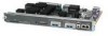
...DATA OK OK POWER SERIES H3590 Series Specifications Design specifications for the Cisco 4000 series follow: • Modular router platform • Flash memory capability • User-upgradable network processor modules, shared memory, and processor local memory • Hardware thermal alarm to warn of excessively high operating ...Series Specifications Figure 1-1 shows the front panel of the single and dual Token Ring, dual Ethernet, and FDDI modules. 1-2 Cisco 4000 Series Hardware Installation and Maintenance The BRI 4-port and 8-port network interface modules (NP-4B/NP-8B) are not ...
...DATA OK OK POWER SERIES H3590 Series Specifications Design specifications for the Cisco 4000 series follow: • Modular router platform • Flash memory capability • User-upgradable network processor modules, shared memory, and processor local memory • Hardware thermal alarm to warn of excessively high operating ...Series Specifications Figure 1-1 shows the front panel of the single and dual Token Ring, dual Ethernet, and FDDI modules. 1-2 Cisco 4000 Series Hardware Installation and Maintenance The BRI 4-port and 8-port network interface modules (NP-4B/NP-8B) are not ...

Hardware Maintenance Manual
Page 21
... is based on the MIPS R4400 and is pin-compatible. 2. Series Specifications Table 1-1 lists the physical specifications for the Cisco 4000 series routers. ROM-Read-only memory. RAM-Random access memory. 4. Cisco 4000 Series Overview 1-3 Table 1-1 Cisco 4000 Series Physical Specifications Description Design Specification Dimensions (W x D x H) 17.6" x 17.7" x 3.4" (44.7 cm x 45 cm x 8.6 cm) Weight 24 lb...
... is based on the MIPS R4400 and is pin-compatible. 2. Series Specifications Table 1-1 lists the physical specifications for the Cisco 4000 series routers. ROM-Read-only memory. RAM-Random access memory. 4. Cisco 4000 Series Overview 1-3 Table 1-1 Cisco 4000 Series Physical Specifications Description Design Specification Dimensions (W x D x H) 17.6" x 17.7" x 3.4" (44.7 cm x 45 cm x 8.6 cm) Weight 24 lb...

Hardware Maintenance Manual
Page 22
... Monitor," and the appendix "Cisco 4500-M and Cisco 4700 ROM Monitor.") Figure 1-2 Cisco 4000 Series Memory Systems and Software Images Cisco 4000 and Cisco 4000-M EPROM-based Flash-memory based Boot helper (xboot) Cisco IOS ROM monitor Cisco 4500, Cisco 4500-M, Cisco 4700, and Cisco 4700-M EPROM-based Flash-memory based ROM monitor Boot helper (xboot) Cisco IOS H3537 1-4 Cisco 4000 Series Hardware Installation and...
... Monitor," and the appendix "Cisco 4500-M and Cisco 4700 ROM Monitor.") Figure 1-2 Cisco 4000 Series Memory Systems and Software Images Cisco 4000 and Cisco 4000-M EPROM-based Flash-memory based Boot helper (xboot) Cisco IOS ROM monitor Cisco 4500, Cisco 4500-M, Cisco 4700, and Cisco 4700-M EPROM-based Flash-memory based ROM monitor Boot helper (xboot) Cisco IOS H3537 1-4 Cisco 4000 Series Hardware Installation and...

Hardware Maintenance Manual
Page 31
...includes an asynchronous router console port (female DB-25 connector) wired as a data communications equipment (DCE) device. The AUX port is included on all Cisco 4000 series routers. The default parameters for this port follow: • 9600 baud • 8 data bits • No parity generated or checked ... found on all router units. Auxiliary Port Connections A male DB-25 connector auxiliary port (labeled AUX on the chassis rear) is a shared-memory data terminal equipment (DTE) port to which you can attach an EIA/TIA-232 connector from a channel service unit/data service unit (CSU/DSU...
...includes an asynchronous router console port (female DB-25 connector) wired as a data communications equipment (DCE) device. The AUX port is included on all Cisco 4000 series routers. The default parameters for this port follow: • 9600 baud • 8 data bits • No parity generated or checked ... found on all router units. Auxiliary Port Connections A male DB-25 connector auxiliary port (labeled AUX on the chassis rear) is a shared-memory data terminal equipment (DTE) port to which you can attach an EIA/TIA-232 connector from a channel service unit/data service unit (CSU/DSU...

Hardware Maintenance Manual
Page 32
...10BaseT connector. (See Figure 2-5.) (Only one per line. Edit with CTRL/Z interface ethernet 0 media-type aui ^z router# write memory Refer to the router software publications for more information on the desired interface. end with DELETE, CTRL/W, and CTRL/U; Enter the media... modules: single-port and dual-port modules. Ethernet Connections The following is an example of network connection available for a Cisco 4000 series router. Network Connection Considerations Network Connection Considerations This section describes the considerations for each type of configuring the Ethernet...
...10BaseT connector. (See Figure 2-5.) (Only one per line. Edit with CTRL/Z interface ethernet 0 media-type aui ^z router# write memory Refer to the router software publications for more information on the desired interface. end with DELETE, CTRL/W, and CTRL/U; Enter the media... modules: single-port and dual-port modules. Ethernet Connections The following is an example of network connection available for a Cisco 4000 series router. Network Connection Considerations Network Connection Considerations This section describes the considerations for each type of configuring the Ethernet...

Hardware Maintenance Manual
Page 46
If a cable is attached to the appropriate software publications. 2-24 Cisco 4000 Series Hardware Installation and Maintenance Network Connection Considerations router> show interface s 0 Serial 0 is up, line protocol is up Hardware is HD64570 Internet ...ds=0x000000 status=80 pak_size=0 08 bd_ptr=0xE280 pak=0x000000 ds=0x000000 status=80 pak_size=0 0 missed datagrams, 0 overruns, 0 bad frame addresses 0 bad datagram encapsulations, 0 memory errors 0 transmitter underruns Note that in the previous example, the cable type is DCE, the output of 250,000 packets. input queue 0/75, 0 drops Five...
If a cable is attached to the appropriate software publications. 2-24 Cisco 4000 Series Hardware Installation and Maintenance Network Connection Considerations router> show interface s 0 Serial 0 is up, line protocol is up Hardware is HD64570 Internet ...ds=0x000000 status=80 pak_size=0 08 bd_ptr=0xE280 pak=0x000000 ds=0x000000 status=80 pak_size=0 0 missed datagrams, 0 overruns, 0 bad frame addresses 0 bad datagram encapsulations, 0 memory errors 0 transmitter underruns Note that in the previous example, the cable type is DCE, the output of 250,000 packets. input queue 0/75, 0 drops Five...

Hardware Maintenance Manual
Page 73
... to be mapped. Installing the Router 3-15 Making Network Connections Step 6 At the prompt, specify the channel-group modification command, channel-group and timeslots to memory as follows: Router# write memory The system will display an OK message when the configuration is stored.
... to be mapped. Installing the Router 3-15 Making Network Connections Step 6 At the prompt, specify the channel-group modification command, channel-group and timeslots to memory as follows: Router# write memory The system will display an OK message when the configuration is stored.

Hardware Maintenance Manual
Page 75
... new ATM module. After you verify that the new interface is recognized by entering disable at the prompt as follows: Router# write memory The system will be the source of the configuration subcommands: Router# conf t Step 2 Specify the unit to configure by entering the...• Static address mappings (address-lists). If you must enter the configuration mode. Making Network Connections Step 9 Write the new configuration to memory as follows: Router# disable Router> Step 11 Check the interface configuration with show a basic ATM configuration using just PVCs. You will recognize...
... new ATM module. After you verify that the new interface is recognized by entering disable at the prompt as follows: Router# write memory The system will be the source of the configuration subcommands: Router# conf t Step 2 Specify the unit to configure by entering the...• Static address mappings (address-lists). If you must enter the configuration mode. Making Network Connections Step 9 Write the new configuration to memory as follows: Router# disable Router> Step 11 Check the interface configuration with show a basic ATM configuration using just PVCs. You will recognize...

Hardware Maintenance Manual
Page 76
...and the ATM forum. A PVC requires the whole path from source to destination to dynamically setup SVCs. Step 10 Write the new configuration to memory: Router# write memory Step 11 Exit the privileged level and return to VCs: Router(config-if)# map-list list1 Router(config-map-list)# ip 1.1.1.2 atm-vc 1... by the signaling software to communicate with the switch in the path, it has to PVCs. Router(config-if)# atm pvc 1 0 5 qsaal 3-18 Cisco 4000 Series Hardware Installation and Maintenance The PVC command has the format atm pvc vc-id vpi vci encap [peak-rate sustained-rate burst-size...
...and the ATM forum. A PVC requires the whole path from source to destination to dynamically setup SVCs. Step 10 Write the new configuration to memory: Router# write memory Step 11 Exit the privileged level and return to VCs: Router(config-if)# map-list list1 Router(config-map-list)# ip 1.1.1.2 atm-vc 1... by the signaling software to communicate with the switch in the path, it has to PVCs. Router(config-if)# atm pvc 1 0 5 qsaal 3-18 Cisco 4000 Series Hardware Installation and Maintenance The PVC command has the format atm pvc vc-id vpi vci encap [peak-rate sustained-rate burst-size...

Hardware Maintenance Manual
Page 77
Step 11 Write the new configuration to memory: Router# write memory Step 12 Exit the privileged level and return to the user level: Router# disable Connecting Routers with a DC-input power supply; For identification purposes, Figure 3-13 shows a Cisco 4000 series router with a DC-Input Power Supply Warning ...Before conducting any of the circuit breaker in this section for proper wiring. Figure 3-14 shows a Cisco 4000 series router with a DC-Input Power Supply Step 6 Configure the ATM NSAP address: Router(config-if)# atm nsap-address nsap-addrr ...
Step 11 Write the new configuration to memory: Router# write memory Step 12 Exit the privileged level and return to the user level: Router# disable Connecting Routers with a DC-input power supply; For identification purposes, Figure 3-13 shows a Cisco 4000 series router with a DC-Input Power Supply Warning ...Before conducting any of the circuit breaker in this section for proper wiring. Figure 3-14 shows a Cisco 4000 series router with a DC-Input Power Supply Step 6 Configure the ATM NSAP address: Router(config-if)# atm nsap-address nsap-addrr ...

Hardware Maintenance Manual
Page 95
... Router 5-1 Before performing any procedures described in this chapter, review the following sections: • Accessing the Router Internal Components • Removing Network Processor Modules • Memory Replacement Procedures • Replacing Network Processor Modules • Replacing the Component Tray • Testing Your Installation Caution Before opening the router chassis, ensure that ship...
... Router 5-1 Before performing any procedures described in this chapter, review the following sections: • Accessing the Router Internal Components • Removing Network Processor Modules • Memory Replacement Procedures • Replacing Network Processor Modules • Replacing the Component Tray • Testing Your Installation Caution Before opening the router chassis, ensure that ship...

Hardware Maintenance Manual
Page 98
... must first remove the network processor modules. Slide the component tray out of the chassis shell. Caution Some network processor modules are replacing shared memory single in-line memory modules (SIMMs), you must be removed before the module can be safely lifted out of the chassis, otherwise damage to the chassis. Other... end of the network processor module, and the two external rear mounting screws (not shown) if the module has them, and set the screws aside. 5-4 Cisco 4000 Series Hardware Installation and Maintenance
... must first remove the network processor modules. Slide the component tray out of the chassis shell. Caution Some network processor modules are replacing shared memory single in-line memory modules (SIMMs), you must be removed before the module can be safely lifted out of the chassis, otherwise damage to the chassis. Other... end of the network processor module, and the two external rear mounting screws (not shown) if the module has them, and set the screws aside. 5-4 Cisco 4000 Series Hardware Installation and Maintenance

Hardware Maintenance Manual
Page 100
... Female module connector on the motherboard Memory Replacement Procedures There are two dynamic random-access memory (DRAM) systems in Cisco 4000 series routers. the Cisco 4500-M and Cisco 4700 have Flash memory for the system software image and for... storing the system software image; The Cisco 4500-M and Cisco 4700 shared memory upgrade permits you remove or replace SIMMs. The Cisco 4000-M main memory upgrade requires replacing the main memory...
... Female module connector on the motherboard Memory Replacement Procedures There are two dynamic random-access memory (DRAM) systems in Cisco 4000 series routers. the Cisco 4500-M and Cisco 4700 have Flash memory for the system software image and for... storing the system software image; The Cisco 4500-M and Cisco 4700 shared memory upgrade permits you remove or replace SIMMs. The Cisco 4000-M main memory upgrade requires replacing the main memory...
