
Hardware Maintenance Manual
Page 21
... noncondensing Operating Temperature 32 to 104°F (0 to 16 MB 1. Table 1-2 Cisco 4000 Series Processor and Memory Specifications Description Processor Main Memory (DRAM)2 Cisco 4000-M Cisco 4500-M Cisco 4700 40-MHz Motorola 68EC030 100-MHz IDT Orion RISC1 133-MHz IDT Orion RISC... random access memory. 3. Table 1-1 Cisco 4000 Series Physical Specifications Description Design Specification Dimensions (W x D x H) 17.6" x 17.7" x 3.4" (44.7 cm x 45 cm x 8.6 cm) Weight 24 lb (10.9 kg) (including the chassis and network processor modules) Power Wire Gauge for DC-Input Power...
... noncondensing Operating Temperature 32 to 104°F (0 to 16 MB 1. Table 1-2 Cisco 4000 Series Processor and Memory Specifications Description Processor Main Memory (DRAM)2 Cisco 4000-M Cisco 4500-M Cisco 4700 40-MHz Motorola 68EC030 100-MHz IDT Orion RISC1 133-MHz IDT Orion RISC... random access memory. 3. Table 1-1 Cisco 4000 Series Physical Specifications Description Design Specification Dimensions (W x D x H) 17.6" x 17.7" x 3.4" (44.7 cm x 45 cm x 8.6 cm) Weight 24 lb (10.9 kg) (including the chassis and network processor modules) Power Wire Gauge for DC-Input Power...
Hardware Maintenance Manual
Page 68
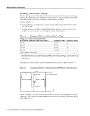
...expansion cards fitted. The larger dimensions, in parentheses, must be applied when the equipment is installed in Figure 3-9, X indicates the clearance distances between cards and adjacent cards and components, and Y shows the creepage path across the surface of an insulator, between BRI Module and Components Host Card Adjacent card...line of sight). • Creepage distances are measured between adjacent parts as shown in Table 3-3 must be maintained between the two points indicated by Other Parts of the Host or Expansion Card... the cards and ...host chassis expansion slot, clearance...
...expansion cards fitted. The larger dimensions, in parentheses, must be applied when the equipment is installed in Figure 3-9, X indicates the clearance distances between cards and adjacent cards and components, and Y shows the creepage path across the surface of an insulator, between BRI Module and Components Host Card Adjacent card...line of sight). • Creepage distances are measured between adjacent parts as shown in Table 3-3 must be maintained between the two points indicated by Other Parts of the Host or Expansion Card... the cards and ...host chassis expansion slot, clearance...

Hardware Maintenance Manual
Page 137
... (boot) C-2 Basic Rate Interface See BRI boot command D-3 boot ROMs, replacing 5-19 booting from Flash B-6 from the ROM monitor Cisco 4000-M C-2 Cisco 4500-M D-3 Cisco 4700 D-3 bootstrap clear memory contents C-2 stack trace, system software C-2 Break key (interrupt) C-1, D-1 BRI distance limitations 2-30, 3-6... 2-3 ungrounded 2-3 uninsulated 2-3 caution, description xvii CE1 cable A-23 network processor module 2-32 channel service unit/digital service unit See CSU/DSU chassis connecting 2-7 dimensions 1-3 opening 5-1 rear view 2-8 Index 3 INDEX Symbols $ command (toggle cache state) C-2 ?...
... (boot) C-2 Basic Rate Interface See BRI boot command D-3 boot ROMs, replacing 5-19 booting from Flash B-6 from the ROM monitor Cisco 4000-M C-2 Cisco 4500-M D-3 Cisco 4700 D-3 bootstrap clear memory contents C-2 stack trace, system software C-2 Break key (interrupt) C-1, D-1 BRI distance limitations 2-30, 3-6... 2-3 ungrounded 2-3 uninsulated 2-3 caution, description xvii CE1 cable A-23 network processor module 2-32 channel service unit/digital service unit See CSU/DSU chassis connecting 2-7 dimensions 1-3 opening 5-1 rear view 2-8 Index 3 INDEX Symbols $ command (toggle cache state) C-2 ?...