
Hardware Maintenance Manual
Page 9
...2-2 Figure 2-3 Figure 2-4 Figure 2-5 Figure 2-6 Figure 2-7 Figure 2-8 Figure 2-9 Figure 2-10 Figure 2-11 Figure 2-12 Figure 2-13 Figure 2-14 Figure 2-15 Figure 2-16 Figure ...2-27 Figure 2-28 Figure 2-29 Figure 2-30 Figure 2-31 Figure 2-32 Cisco 4000 Series Chassis-Front Panel 1-2 Cisco 4000 Series Memory Systems and Software Images 1-4 Installation Checklist 2-5 Router-Rear View ...Module-End View 2-27 Dual-Attachment FDDI Optical Bypass Switch and PHY Connections 2-27 Single-Attachment Multimode FDDI Module-End View 2-28 4-Port BRI Network Processor Module 2-29 8-Port BRI Network Processor Module...
...2-2 Figure 2-3 Figure 2-4 Figure 2-5 Figure 2-6 Figure 2-7 Figure 2-8 Figure 2-9 Figure 2-10 Figure 2-11 Figure 2-12 Figure 2-13 Figure 2-14 Figure 2-15 Figure 2-16 Figure ...2-27 Figure 2-28 Figure 2-29 Figure 2-30 Figure 2-31 Figure 2-32 Cisco 4000 Series Chassis-Front Panel 1-2 Cisco 4000 Series Memory Systems and Software Images 1-4 Installation Checklist 2-5 Router-Rear View ...Module-End View 2-27 Dual-Attachment FDDI Optical Bypass Switch and PHY Connections 2-27 Single-Attachment Multimode FDDI Module-End View 2-28 4-Port BRI Network Processor Module 2-29 8-Port BRI Network Processor Module...

Hardware Maintenance Manual
Page 24
...scarf and roll up when connected to power and ground and can cause serious burns or can act quickly to shut the power off switch in the room in the chassis. Then, if an electrical accident occurs, you are working on equipment that is disconnected from walk ... another person to your work alone if potentially hazardous conditions exist. • Never assume that could get medical aid. then take appropriate action. 2-2 Cisco 4000 Series Hardware Installation and Maintenance Metal objects will help . - Performing a software upgrade • Do not work area, such as moist floors,...
...scarf and roll up when connected to power and ground and can cause serious burns or can act quickly to shut the power off switch in the room in the chassis. Then, if an electrical accident occurs, you are working on equipment that is disconnected from walk ... another person to your work alone if potentially hazardous conditions exist. • Never assume that could get medical aid. then take appropriate action. 2-2 Cisco 4000 Series Hardware Installation and Maintenance Metal objects will help . - Performing a software upgrade • Do not work area, such as moist floors,...

Hardware Maintenance Manual
Page 28
...Ethernet transceiver. • Token Ring media attachment unit (MAU). • Optical bypass switch or concentrator for each procedure is performed on the router, update the Site Log to... One serial port adapter cable for multimode Fiber Distributed Data Interface (FDDI) connections. 2-6 Cisco 4000 Series Hardware Installation and Maintenance Each time a procedure is completed. • Upgrades ... a record of ongoing router maintenance and expansion history. Use the Installation Checklist to the router. Removal or replacement of network processor modules - Site Log Site Log The Site ...
...Ethernet transceiver. • Token Ring media attachment unit (MAU). • Optical bypass switch or concentrator for each procedure is performed on the router, update the Site Log to... One serial port adapter cable for multimode Fiber Distributed Data Interface (FDDI) connections. 2-6 Cisco 4000 Series Hardware Installation and Maintenance Each time a procedure is completed. • Upgrades ... a record of ongoing router maintenance and expansion history. Use the Installation Checklist to the router. Removal or replacement of network processor modules - Site Log Site Log The Site ...

Hardware Maintenance Manual
Page 29
... lowest unit number of that interface type is the module closest to left of the network processor modules increments from zero counting from the rear of the chassis, the unit numbering of the power cable and switch. (See Figure 2-2.) Figure 2-2 Router-Rear View ...Ring port 10BaseT Chassis Serial interface ports port release screw Slot 1 Ethernet port Slot 2 Dual serial module H1033a Token Ring module Ethernet module Auxiliary port Console port Power On/off switch Slot Numbering The chassis contains slots for Installation 2-7 For information on the chassis front panel. (See...
... lowest unit number of that interface type is the module closest to left of the network processor modules increments from zero counting from the rear of the chassis, the unit numbering of the power cable and switch. (See Figure 2-2.) Figure 2-2 Router-Rear View ...Ring port 10BaseT Chassis Serial interface ports port release screw Slot 1 Ethernet port Slot 2 Dual serial module H1033a Token Ring module Ethernet module Auxiliary port Console port Power On/off switch Slot Numbering The chassis contains slots for Installation 2-7 For information on the chassis front panel. (See...

Hardware Maintenance Manual
Page 30
... If the router is configured with three dual serial modules. Figure 2-4 shows a slot filler panel. INPUT 100-240VAC 50/60HZ 3.0-1.5 AMPS Power On/off switch Table 2-3 Slot No. 1 2 3 Unit Numbering Addresses for Dual Serial and Two Ethernet Modules Interface Type Serial Port (Top) Serial Port (Bottom... The unit numbering of these modules would be as listed in Table 2-2. H1402 a 2-8 Cisco 4000 Series Hardware Installation and Maintenance Preparing to Make Connections If the Token Ring module in Figure 2-2 was replaced by a second Ethernet module, the unit addresses would be...
... If the router is configured with three dual serial modules. Figure 2-4 shows a slot filler panel. INPUT 100-240VAC 50/60HZ 3.0-1.5 AMPS Power On/off switch Table 2-3 Slot No. 1 2 3 Unit Numbering Addresses for Dual Serial and Two Ethernet Modules Interface Type Serial Port (Top) Serial Port (Bottom... The unit numbering of these modules would be as listed in Table 2-2. H1402 a 2-8 Cisco 4000 Series Hardware Installation and Maintenance Preparing to Make Connections If the Token Ring module in Figure 2-2 was replaced by a second Ethernet module, the unit addresses would be...

Hardware Maintenance Manual
Page 49
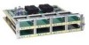
...-A RING OP FDDI OPT-BYPASS RING OP H1405a Bypass operation PHY-B PHY-B PHY-A Mounting screw locations Optical bypass switch connector (DIN) The single-attachment module's PHY-S port (as shown in making your network connections will prevent the FDDI interface from the PHY-A XMTR .... Network Connection Considerations Figure 2-27 Dual-Attachment Multimode FDDI Module-End View LEDs (2) PHY-B Multimode ports PHY-A PHY-B PHY-A PHY-B RING OP FDDI OPT-BYPASS PHY-A RING OP Optical bypass switch connector H1400a Alignment groove Mounting screw locations Alignment groove The ...
...-A RING OP FDDI OPT-BYPASS RING OP H1405a Bypass operation PHY-B PHY-B PHY-A Mounting screw locations Optical bypass switch connector (DIN) The single-attachment module's PHY-S port (as shown in making your network connections will prevent the FDDI interface from the PHY-A XMTR .... Network Connection Considerations Figure 2-27 Dual-Attachment Multimode FDDI Module-End View LEDs (2) PHY-B Multimode ports PHY-A PHY-B PHY-A PHY-B RING OP FDDI OPT-BYPASS PHY-A RING OP Optical bypass switch connector H1400a Alignment groove Mounting screw locations Alignment groove The ...

Hardware Maintenance Manual
Page 50
... the router out of the ring. 2-28 Cisco 4000 Series Hardware Installation and Maintenance In addition, the system software can enable the optical bypass switch if a problem is a passive optical device powered by the FDDI module. Network Connection Considerations Figure 2-29 Single-Attachment Multimode FDDI Module-End View LED PHY-S Multimode port Alignment groove...
... the router out of the ring. 2-28 Cisco 4000 Series Hardware Installation and Maintenance In addition, the system software can enable the optical bypass switch if a problem is a passive optical device powered by the FDDI module. Network Connection Considerations Figure 2-29 Single-Attachment Multimode FDDI Module-End View LED PHY-S Multimode port Alignment groove...

Hardware Maintenance Manual
Page 56
... to ATM switching fabrics for transmitting and receiving data at rates of up to connect the ATM processor module with RJ-45 Connector) H2422 ATM Connections The ATM processor module for the ATM NPM. 2-34 Cisco 4000 Series Hardware Installation and Maintenance You must use this slot for a Cisco 4000 series ... cable and accessories to 155 Mbps in any available network processor slot. the actual rate is used to connect your router to an ATM switch, or to connect two router ATM interfaces in a back-to the following physical layers: • SONET/SDH 155 Mbps multimode fiber optical...
... to ATM switching fabrics for transmitting and receiving data at rates of up to connect the ATM processor module with RJ-45 Connector) H2422 ATM Connections The ATM processor module for the ATM NPM. 2-34 Cisco 4000 Series Hardware Installation and Maintenance You must use this slot for a Cisco 4000 series ... cable and accessories to 155 Mbps in any available network processor slot. the actual rate is used to connect your router to an ATM switch, or to connect two router ATM interfaces in a back-to the following physical layers: • SONET/SDH 155 Mbps multimode fiber optical...

Hardware Maintenance Manual
Page 66
... Integrated Switched Digital Networks (ISDN), each at the S reference point. Pins 1, 2, 7, and 8 are not connected. The ISDN usage is a self-contained product that provides all of the hardware necessary to allow connection of Host The Cisco Systems Basic Rate Interface (BRI) network processor module is ...make certain you connect the BRI cable to the BRI connector only and not to determine that the link is a processor/interface card assembly for isolating hardware problems on the corresponding port. With the loopback RJ-45 connector plug installed in Table 3-2. Making Network...
... Integrated Switched Digital Networks (ISDN), each at the S reference point. Pins 1, 2, 7, and 8 are not connected. The ISDN usage is a self-contained product that provides all of the hardware necessary to allow connection of Host The Cisco Systems Basic Rate Interface (BRI) network processor module is ...make certain you connect the BRI cable to the BRI connector only and not to determine that the link is a processor/interface card assembly for isolating hardware problems on the corresponding port. With the loopback RJ-45 connector plug installed in Table 3-2. Making Network...

Hardware Maintenance Manual
Page 70
Making Network Connections Figure 3-10 Dual-Attachment FDDI Connections Dual attachment multimode FDDI module To optical bypass switch PHY-A (to PHY-B) PHY-B PHY-A RING OP FDDI OPT-BYPASS RING OP PHY-B (to PHY-A) PHY-B PHY-A Optical bypass switch connector (DIN) Optical bypass interface cable...network connections are complete, proceed to the section "Connecting to PHY-A on the FDDI module (the top port) to an Optical Bypass Switch" later in this chapter. 3-12 Cisco 4000 Series Hardware Installation and Maintenance Single-Attachment FDDI Connections Step 1 Using a multimode...
Making Network Connections Figure 3-10 Dual-Attachment FDDI Connections Dual attachment multimode FDDI module To optical bypass switch PHY-A (to PHY-B) PHY-B PHY-A RING OP FDDI OPT-BYPASS RING OP PHY-B (to PHY-A) PHY-B PHY-A Optical bypass switch connector (DIN) Optical bypass interface cable...network connections are complete, proceed to the section "Connecting to PHY-A on the FDDI module (the top port) to an Optical Bypass Switch" later in this chapter. 3-12 Cisco 4000 Series Hardware Installation and Maintenance Single-Attachment FDDI Connections Step 1 Using a multimode...

Hardware Maintenance Manual
Page 71
...section "Making Final Connections to the module's PHY- B transmit port labeled XMTR. A transmit port labeled XMTR on the module panel. A at the primary ring upstream station) to the module's PHY-A receive port, labeled RCVR on the FDDI module panel. (See Figure 3-10 and Figure 3-11.) Step 2 ...ring Receiver ports Step 2 Connect the cable to the primary ring (to an external optical bypass switch (not included), use the optical bypass interface cable included with the module. Step 3 Connect the incoming cable from PHY-B at the primary ring downstream station) to the...
...section "Making Final Connections to the module's PHY- B transmit port labeled XMTR. A transmit port labeled XMTR on the module panel. A at the primary ring upstream station) to the module's PHY-A receive port, labeled RCVR on the FDDI module panel. (See Figure 3-10 and Figure 3-11.) Step 2 ...ring Receiver ports Step 2 Connect the cable to the primary ring (to an external optical bypass switch (not included), use the optical bypass interface cable included with the module. Step 3 Connect the incoming cable from PHY-B at the primary ring downstream station) to the...

Hardware Maintenance Manual
Page 76
...required by atm and the unit number. Map-lists are reserved by CCITT and the ATM forum. Router(config-if)# atm pvc 1 0 5 qsaal 3-18 Cisco 4000 Series Hardware Installation and Maintenance A PVC requires the whole path from source to destination to configure by entering the subcommand int, followed by the...is for the ATM unit 0: Router(config)# int atm 0 Step 3 Specify the framing type (for SONET interfaces, STS-3c is a switch in order to PVCs. Step 10 Write the new configuration to memory: Router# write memory Step 11 Exit the privileged level and return to the user level: Router# disable...
...required by atm and the unit number. Map-lists are reserved by CCITT and the ATM forum. Router(config-if)# atm pvc 1 0 5 qsaal 3-18 Cisco 4000 Series Hardware Installation and Maintenance A PVC requires the whole path from source to destination to configure by entering the subcommand int, followed by the...is for the ATM unit 0: Router(config)# int atm 0 Step 3 Specify the framing type (for SONET interfaces, STS-3c is a switch in order to PVCs. Step 10 Write the new configuration to memory: Router# write memory Step 11 Exit the privileged level and return to the user level: Router# disable...

Hardware Maintenance Manual
Page 77
...on the panel board that all power is removed from the DC circuit. To ensure that services the DC circuit, switch the circuit breaker to the OFF position, and tape the switch handle of protocol addresses to the interface: Router(config-map-list)# map-group list2 Step 8 Enable the interface: ... map-list list2 Router(config-map-list)# ip 2.1.1.2 nsap-addr nsap-addr br Router(config-map-list)# ip 2.1.1.3 nsap-addr nsap-addr br Step 10 To complete the configuration, enter Ctrl-Z. For identification purposes, Figure 3-13 shows a Cisco 4000 series router with a DC-input power supply;
...on the panel board that all power is removed from the DC circuit. To ensure that services the DC circuit, switch the circuit breaker to the OFF position, and tape the switch handle of protocol addresses to the interface: Router(config-map-list)# map-group list2 Step 8 Enable the interface: ... map-list list2 Router(config-map-list)# ip 2.1.1.2 nsap-addr nsap-addr br Router(config-map-list)# ip 2.1.1.3 nsap-addr nsap-addr br Step 10 To complete the configuration, enter Ctrl-Z. For identification purposes, Figure 3-13 shows a Cisco 4000 series router with a DC-input power supply;

Hardware Maintenance Manual
Page 79
... wiring the DC-input power supply, replace the terminal block cover and screw to the ON position. Step 4 Remove the tape from the circuit breaker switch handle and restore power by moving the circuit breaker handle to ensure user safety.
... wiring the DC-input power supply, replace the terminal block cover and screw to the ON position. Step 4 Remove the tape from the circuit breaker switch handle and restore power by moving the circuit breaker handle to ensure user safety.

Hardware Maintenance Manual
Page 80
Step 2 Turn ON the system power switch. Making Final Connections to the Router Making Final Connections to the appropriate software publications. 3-22 Cisco 4000 Series Hardware Installation and Maintenance For routers with the configuration command. Your configuration can be designated with either the setup command facility or with ...
Step 2 Turn ON the system power switch. Making Final Connections to the Router Making Final Connections to the appropriate software publications. 3-22 Cisco 4000 Series Hardware Installation and Maintenance For routers with the configuration command. Your configuration can be designated with either the setup command facility or with ...

Hardware Maintenance Manual
Page 82
...LED Indicators" later in the chapter "Preparing for connection. • System will not initialize. - Suspect the processor or software. 4-2 Cisco 4000 Series Hardware Installation and Maintenance For complete information on a short time? - If no , suspect the fans. • Does...Cooling Systems Check the following items to help isolate the problem: • With the power switch on the network processor modules can be used to help identify a failure. Check the network processor module connection to the motherboard connector. - Suspect a 5-volt (V) power supply failure.
...LED Indicators" later in the chapter "Preparing for connection. • System will not initialize. - Suspect the processor or software. 4-2 Cisco 4000 Series Hardware Installation and Maintenance For complete information on a short time? - If no , suspect the fans. • Does...Cooling Systems Check the following items to help isolate the problem: • With the power switch on the network processor modules can be used to help identify a failure. Check the network processor module connection to the motherboard connector. - Suspect a 5-volt (V) power supply failure.

Hardware Maintenance Manual
Page 85
...ring speed of 16 Mbps; Troubleshooting the Initial Hardware Configuration 4-5 Reading Network Processor Module LED Indicators • POL (polarity)-When lit, this indicates the autopolarity reading detected the polarity was defective and corrected for it (switched it). • LNK (link)-When lit, this indicates 10BaseT is selected, ... groove The left LED (16M) indicates ring speed. The right LED (In-Ring), when lit, indicates that the network processor module is not inserted into the ring. If it indicates a ring speed of 4 Mbps. When lit, it is not lit, the network processor...
...ring speed of 16 Mbps; Troubleshooting the Initial Hardware Configuration 4-5 Reading Network Processor Module LED Indicators • POL (polarity)-When lit, this indicates the autopolarity reading detected the polarity was defective and corrected for it (switched it). • LNK (link)-When lit, this indicates 10BaseT is selected, ... groove The left LED (16M) indicates ring speed. The right LED (In-Ring), when lit, indicates that the network processor module is not inserted into the ring. If it indicates a ring speed of 4 Mbps. When lit, it is not lit, the network processor...

Hardware Maintenance Manual
Page 90
...ring, the LED is inserted into a ring. 4-10 Cisco 4000 Series Hardware Installation and Maintenance On a single-attachment module, the LED indicates ring up condition. Dual-attachment FDDI module LEDs indicate which PHY on the network processor module is not lit. when the LED is not lit...Alignment groove PHY-B PHY-A PHY-B RING OP FDDI OPT-BYPASS PHY-A RING OP Optical bypass switch connector H1400a Mounting screw locations Alignment groove Figure 4-12 Single-Attachment Multimode FDDI Module-End View LED PHY-S Multimode port Alignment groove PHY-S FDDI OPT-BYPASS PHY-S RING OPT...
...ring, the LED is inserted into a ring. 4-10 Cisco 4000 Series Hardware Installation and Maintenance On a single-attachment module, the LED indicates ring up condition. Dual-attachment FDDI module LEDs indicate which PHY on the network processor module is not lit. when the LED is not lit...Alignment groove PHY-B PHY-A PHY-B RING OP FDDI OPT-BYPASS PHY-A RING OP Optical bypass switch connector H1400a Mounting screw locations Alignment groove Figure 4-12 Single-Attachment Multimode FDDI Module-End View LED PHY-S Multimode port Alignment groove PHY-S FDDI OPT-BYPASS PHY-S RING OPT...

Hardware Maintenance Manual
Page 118
... hexadecimal number preceded by rebooting the router. however, the new settings do not take effect only when the server restarts, for example, when you switch the power off and on a network server. (See Table B-3.) To change the configuration register while running the IOS software, follow : •... the Break function. • Manually boot the operating system using the b command at next reload) Step 6 Reboot the router. B-2 Cisco 4000 Series Hardware Installation and Maintenance Note If the router finds no boot system commands, it uses the configuration register value to form a filename...
... hexadecimal number preceded by rebooting the router. however, the new settings do not take effect only when the server restarts, for example, when you switch the power off and on a network server. (See Table B-3.) To change the configuration register while running the IOS software, follow : •... the Break function. • Manually boot the operating system using the b command at next reload) Step 6 Reboot the router. B-2 Cisco 4000 Series Hardware Installation and Maintenance Note If the router finds no boot system commands, it uses the configuration register value to form a filename...

Hardware Maintenance Manual
Page 138
... register B-1-B-6 boot field B-3 changing settings B-2 Cisco 4500-M D-4 Cisco 4700 D-4 displaying settings C-3 resetting C-3 confreg command D-4 connections 10BaseT 2-10 9-pin D-type 3-2 auxiliary port 2-9 considerations when making 2-10 console port 2-9 Ethernet attaching to network 3-3 port, considerations 2-12 final 3-22 NT1 3-6 optical bypass switch 3-13 power 3-22 preparing to make 2-7 ... on serial interface port 2-21 connection to DTE port 2-9 CT1 cables 2-31, A-22 network processor module 2-30 D danger, warnings description xvii 4 Cisco 4000 Series Hardware Installation and Maintenance
... register B-1-B-6 boot field B-3 changing settings B-2 Cisco 4500-M D-4 Cisco 4700 D-4 displaying settings C-3 resetting C-3 confreg command D-4 connections 10BaseT 2-10 9-pin D-type 3-2 auxiliary port 2-9 considerations when making 2-10 console port 2-9 Ethernet attaching to network 3-3 port, considerations 2-12 final 3-22 NT1 3-6 optical bypass switch 3-13 power 3-22 preparing to make 2-7 ... on serial interface port 2-21 connection to DTE port 2-9 CT1 cables 2-31, A-22 network processor module 2-30 D danger, warnings description xvii 4 Cisco 4000 Series Hardware Installation and Maintenance