
Hardware Installation Guide
Page 2
... OTHER WARRANTY HEREIN, ALL DOCUMENT FILES AND SOFTWARE OF THESE SUPPLIERS ARE PROVIDED "AS IS" WITH ALL FAULTS. Cisco UCS 6100 Series Fabric Interconnect Hardware Installation Guide © 2009-2010 Cisco Systems, Inc. If it was probably caused by FCC regulations, and you may result in part 15 of its affiliates in a residential installation. Modifying the equipment without Cisco's written authorization may...
... OTHER WARRANTY HEREIN, ALL DOCUMENT FILES AND SOFTWARE OF THESE SUPPLIERS ARE PROVIDED "AS IS" WITH ALL FAULTS. Cisco UCS 6100 Series Fabric Interconnect Hardware Installation Guide © 2009-2010 Cisco Systems, Inc. If it was probably caused by FCC regulations, and you may result in part 15 of its affiliates in a residential installation. Modifying the equipment without Cisco's written authorization may...

Hardware Installation Guide
Page 3
... 1-1 Cisco UCS 6120XP Chassis 1-2 Cisco UCS 6140XP Chassis 1-4 Expansion Modules 1-6 N10-E0440 1-7 N10-E0600 1-8 N10-E0080 1-8 N10-E0060 1-9 Ports 1-10 Cisco UCS 6120XP 1-10 Cisco UCS 6140XP 1-12 Power Supply 1-14 Fan Module 1-16 LED Descriptions 1-17 Port Level LEDs 1-18 Supported Transceivers 1-18 SFP+ Transceivers 1-18 SFP Transceivers 1-19 SFP+ Copper Cables 1-19 SFP Fibre Channel Transceivers 1-19 Installing the Cisco UCS 6100 Series Fabric Interconnect 2-1 Preparing for Installation 2-2 Installation Options 2-2 Cisco UCS 6100 Series Fabric Interconnect Hardware Installation Guide iii
... 1-1 Cisco UCS 6120XP Chassis 1-2 Cisco UCS 6140XP Chassis 1-4 Expansion Modules 1-6 N10-E0440 1-7 N10-E0600 1-8 N10-E0080 1-8 N10-E0060 1-9 Ports 1-10 Cisco UCS 6120XP 1-10 Cisco UCS 6140XP 1-12 Power Supply 1-14 Fan Module 1-16 LED Descriptions 1-17 Port Level LEDs 1-18 Supported Transceivers 1-18 SFP+ Transceivers 1-18 SFP Transceivers 1-19 SFP+ Copper Cables 1-19 SFP Fibre Channel Transceivers 1-19 Installing the Cisco UCS 6100 Series Fabric Interconnect 2-1 Preparing for Installation 2-2 Installation Options 2-2 Cisco UCS 6100 Series Fabric Interconnect Hardware Installation Guide iii
Hardware Installation Guide
Page 4
...2-24 Removing a Power Supply 2-24 Installing a Power Supply 2-25 Fan Modules 2-26 Replacing a Fan Module 2-26 Removing the Cisco UCS 6120XP 2-28 Removing the Cisco UCS 6140XP 2-28 Repacking the Cisco UCS Fabric Interconnect for Return Shipment 2-29 3 C H A P T E R Connecting the Cisco UCS 6100 Series Fabric Interconnect 3-1 Preparing for Network Connections 3-1 Connecting to the Console Port 3-1 Connecting to the Ethernet Connector Port 3-3 Connecting to an Ethernet Port 3-3 Installing or Removing SFP+ Transceivers 3-4 Cisco UCS 6100 Series Fabric Interconnect Hardware Installation Guide iv...
...2-24 Removing a Power Supply 2-24 Installing a Power Supply 2-25 Fan Modules 2-26 Replacing a Fan Module 2-26 Removing the Cisco UCS 6120XP 2-28 Removing the Cisco UCS 6140XP 2-28 Repacking the Cisco UCS Fabric Interconnect for Return Shipment 2-29 3 C H A P T E R Connecting the Cisco UCS 6100 Series Fabric Interconnect 3-1 Preparing for Network Connections 3-1 Connecting to the Console Port 3-1 Connecting to the Ethernet Connector Port 3-3 Connecting to an Ethernet Port 3-3 Installing or Removing SFP+ Transceivers 3-4 Cisco UCS 6100 Series Fabric Interconnect Hardware Installation Guide iv...

Hardware Installation Guide
Page 15
...; Cisco UCS 6140XP Chassis, page 1-4 • Expansion Modules, page 1-6 • Ports, page 1-10 • Power Supply, page 1-14 • Fan Module, page 1-16 • LED Descriptions, page 1-17 • Supported Transceivers, page 1-18 Interconnect Features A Cisco UCS 6100 series fabric interconnect is a top-of the chassis. Each fan module houses six fans. Servers connect to the fabric interconnect, and it connects to both production Ethernet LANs and Fibre Channel SANs in the rack. The Cisco...
...; Cisco UCS 6140XP Chassis, page 1-4 • Expansion Modules, page 1-6 • Ports, page 1-10 • Power Supply, page 1-14 • Fan Module, page 1-16 • LED Descriptions, page 1-17 • Supported Transceivers, page 1-18 Interconnect Features A Cisco UCS 6100 series fabric interconnect is a top-of the chassis. Each fan module houses six fans. Servers connect to the fabric interconnect, and it connects to both production Ethernet LANs and Fibre Channel SANs in the rack. The Cisco...

Hardware Installation Guide
Page 16
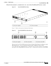
... chassis. The chassis has two power supplies and two fan modules on the front of the chassis, and it has network ports on the rear of the Cisco UCS 6120XP. Figure 1-1 Ethernet Connector Port 1 2 186385 1 UCS cluster cross connect ports 2 Network management ports Table 1-1 lists the LED descriptions for all Ethernet LEDs. Cisco UCS 6120XP Chassis Chapter 1 Product Overview Send document comments to back. Cisco UCS 6100 Series Fabric Interconnect Hardware Installation Guide 1-2 OL-20036-02 Figure 1-1 shows a close-up view...
... chassis. The chassis has two power supplies and two fan modules on the front of the chassis, and it has network ports on the rear of the Cisco UCS 6120XP. Figure 1-1 Ethernet Connector Port 1 2 186385 1 UCS cluster cross connect ports 2 Network management ports Table 1-1 lists the LED descriptions for all Ethernet LEDs. Cisco UCS 6120XP Chassis Chapter 1 Product Overview Send document comments to back. Cisco UCS 6100 Series Fabric Interconnect Hardware Installation Guide 1-2 OL-20036-02 Figure 1-1 shows a close-up view...
Hardware Installation Guide
Page 17
... Overview Cisco UCS 6120XP Chassis Send document comments to eight of the Cisco UCS 6120XP. OL-20036-02 Cisco UCS 6100 Series Fabric Interconnect Hardware Installation Guide 1-3 Figure 1-3 Cisco UCS 6120XP Front View Close-up view of the front of the Cisco UCS 6120XP chassis has 20 fixed 10-Gigabit, Fiber Channel over Ethernet-capable SFP+ Ethernet ports, 1 slot for an optional expansion module, an Ethernet connector with 2 cross-connect ports and 2 management ports, a console port, and 2 AC power connectors. Figure...
... Overview Cisco UCS 6120XP Chassis Send document comments to eight of the Cisco UCS 6120XP. OL-20036-02 Cisco UCS 6100 Series Fabric Interconnect Hardware Installation Guide 1-3 Figure 1-3 Cisco UCS 6120XP Front View Close-up view of the front of the Cisco UCS 6120XP chassis has 20 fixed 10-Gigabit, Fiber Channel over Ethernet-capable SFP+ Ethernet ports, 1 slot for an optional expansion module, an Ethernet connector with 2 cross-connect ports and 2 management ports, a console port, and 2 AC power connectors. Figure...

Hardware Installation Guide
Page 18
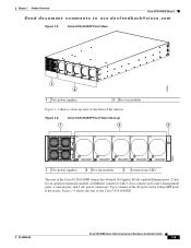
... power supplies and two fan modules on the front of the chassis, and it has network ports on the right (top and bottom) 4 20 fixed SFP+ 10-Gigabit Ethernet ports (up to back. Figure 1-5 shows the front of the chassis. It mounts in a standard 19-inch rack (the Cisco R Series Rack is 2 RU, 3.45 inches tall, 17.3 inches wide and 30.0 inches deep. Cisco UCS 6100 Series Fabric Interconnect Hardware Installation Guide...
... power supplies and two fan modules on the front of the chassis, and it has network ports on the right (top and bottom) 4 20 fixed SFP+ 10-Gigabit Ethernet ports (up to back. Figure 1-5 shows the front of the chassis. It mounts in a standard 19-inch rack (the Cisco R Series Rack is 2 RU, 3.45 inches tall, 17.3 inches wide and 30.0 inches deep. Cisco UCS 6100 Series Fabric Interconnect Hardware Installation Guide...
Hardware Installation Guide
Page 19
...-docfeedback@cisco.com Figure 1-5 Cisco UCS 6140XP Front View 186260 1 2 1 Two power supplies 2 Five fan modules Figure 1-3 shows a close-up 1 2 3 186261 1 Two power supplies 2 Five fan modules 3 System status LED The rear of the Cisco UCS 6140XP chassis has 40 fixed 10-Gigabit, FCoE-capable Ethernet ports, 2 slots for an optional expansion module, an Ethernet connector with 2 cross-connect ports and 2 management ports, a console port, and 2 AC power connectors. OL-20036-02 Cisco UCS 6100 Series Fabric Interconnect Hardware Installation Guide 1-5 Figure 1-6 Cisco UCS...
...-docfeedback@cisco.com Figure 1-5 Cisco UCS 6140XP Front View 186260 1 2 1 Two power supplies 2 Five fan modules Figure 1-3 shows a close-up 1 2 3 186261 1 Two power supplies 2 Five fan modules 3 System status LED The rear of the Cisco UCS 6140XP chassis has 40 fixed 10-Gigabit, FCoE-capable Ethernet ports, 2 slots for an optional expansion module, an Ethernet connector with 2 cross-connect ports and 2 management ports, a console port, and 2 AC power connectors. OL-20036-02 Cisco UCS 6100 Series Fabric Interconnect Hardware Installation Guide 1-5 Figure 1-6 Cisco UCS...

Hardware Installation Guide
Page 20
... 6 AC power connectors 4-port Fibre Channel plus 4-port 10-Gigabit Ethernet expansion modules Expansion Modules Expansion modules allow Cisco UCS 6100 Series Fabric Interconnect to ensure proper airflow in the chassis. The Cisco UCS 6140XP has two slot for an optional uplink expansion module. Cisco UCS 6100 Series Fabric Interconnect Hardware Installation Guide 1-6 OL-20036-02 Expansion Modules Chapter 1 Product Overview Send document comments to ucs-docfeedback@cisco.com Figure 1-7 Cisco UCS 6140XP Rear View 186265 1 2 3 4 5 6 1 System status LED 2 Ethernet connector with...
... 6 AC power connectors 4-port Fibre Channel plus 4-port 10-Gigabit Ethernet expansion modules Expansion Modules Expansion modules allow Cisco UCS 6100 Series Fabric Interconnect to ensure proper airflow in the chassis. The Cisco UCS 6140XP has two slot for an optional uplink expansion module. Cisco UCS 6100 Series Fabric Interconnect Hardware Installation Guide 1-6 OL-20036-02 Expansion Modules Chapter 1 Product Overview Send document comments to ucs-docfeedback@cisco.com Figure 1-7 Cisco UCS 6140XP Rear View 186265 1 2 3 4 5 6 1 System status LED 2 Ethernet connector with...
Hardware Installation Guide
Page 28
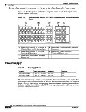
... uses a front-end power supply. The chassis has slots for both the fixed ports and the Ethernet expansion module ports. Figure 1-21 shows the 550 W power supply, which has two LEDs: one for power status and one for failure condition. 1-14 Cisco UCS 6100 Series Fabric Interconnect Hardware Installation Guide OL-20036-02 Figure 1-20 Port Numbering of the Cisco UCS 6140XP Configured with one power supply. Figure 1-22 shows the 750 W power supply, which has two LEDs...
... uses a front-end power supply. The chassis has slots for both the fixed ports and the Ethernet expansion module ports. Figure 1-21 shows the 550 W power supply, which has two LEDs: one for power status and one for failure condition. 1-14 Cisco UCS 6100 Series Fabric Interconnect Hardware Installation Guide OL-20036-02 Figure 1-20 Port Numbering of the Cisco UCS 6140XP Configured with one power supply. Figure 1-22 shows the 750 W power supply, which has two LEDs...
Hardware Installation Guide
Page 32
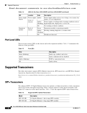
... Model SFP-10G-SR SFP-10G-LR Description 10-Gigabit Ethernet-short range SFP+ module 10-Gigabit Ethernet-long range SFP+ module 1-18 Cisco UCS 6100 Series Fabric Interconnect Hardware Installation Guide OL-20036-02 Table 1-5 summarizes the behavior of chassis) Amber Amber (blinking) Power supply failure such as high temperature, high power, or slow fan. Off No warning or failure condition. It has a 20-pin connector on the electrical interface and duplex LC connector on the expansion modules. Expansion module Back of chassis Green Expansion module...
... Model SFP-10G-SR SFP-10G-LR Description 10-Gigabit Ethernet-short range SFP+ module 10-Gigabit Ethernet-long range SFP+ module 1-18 Cisco UCS 6100 Series Fabric Interconnect Hardware Installation Guide OL-20036-02 Table 1-5 summarizes the behavior of chassis) Amber Amber (blinking) Power supply failure such as high temperature, high power, or slow fan. Off No warning or failure condition. It has a 20-pin connector on the electrical interface and duplex LC connector on the expansion modules. Expansion module Back of chassis Green Expansion module...

Hardware Installation Guide
Page 35
... information. Use the statement number provided at the end of security. Statement 1071 SAVE THESE INSTRUCTIONS Warning This unit is intended for installation in the translated safety warnings that could cause bodily injury. Statement 1030 OL-20036-02 Cisco UCS 6100 Series Fabric Interconnect Hardware Installation Guide 2-1 A restricted access area can be accessed only through the use of a special tool, lock and key, or...
... information. Use the statement number provided at the end of security. Statement 1071 SAVE THESE INSTRUCTIONS Warning This unit is intended for installation in the translated safety warnings that could cause bodily injury. Statement 1030 OL-20036-02 Cisco UCS 6100 Series Fabric Interconnect Hardware Installation Guide 2-1 A restricted access area can be accessed only through the use of a special tool, lock and key, or...

Hardware Installation Guide
Page 54
... fan modules are tight. Step 3 Step 4 Ensure that the chassis is solid metal-to the LAN until the initial system configuration has been performed. For instructions on connecting to the console port, see the "Connecting to power up the fabric interconnect and verify hardware operation, follow these steps: Step 1 Step 2 Verify that empty power supply slots have the required AC power voltages (see theCisco UCS Manager CLI Configuration Guide...
... fan modules are tight. Step 3 Step 4 Ensure that the chassis is solid metal-to the LAN until the initial system configuration has been performed. For instructions on connecting to the console port, see the "Connecting to power up the fabric interconnect and verify hardware operation, follow these steps: Step 1 Step 2 Verify that empty power supply slots have the required AC power voltages (see theCisco UCS Manager CLI Configuration Guide...

Hardware Installation Guide
Page 55
... from Cisco, contact Cisco Technical Support at this product through a Cisco reseller, contact the reseller directly for a replacement. After the system boots, verify that the LED operation is as follows: • Fan module-Status LED is green. • Power supply-Status LED is green. • After initialization, the system status LED is green, indicating that all chassis environmental monitors are enabled, and the LED for the admin account. If you connect the power cable. In a cluster configuration, the...
... from Cisco, contact Cisco Technical Support at this product through a Cisco reseller, contact the reseller directly for a replacement. After the system boots, verify that the LED operation is as follows: • Fan module-Status LED is green. • Power supply-Status LED is green. • After initialization, the system status LED is green, indicating that all chassis environmental monitors are enabled, and the LED for the admin account. If you connect the power cable. In a cluster configuration, the...

Hardware Installation Guide
Page 56
... Installing Expansion Modules, page 2-22 • Replacing or Installing Power Supplies, page 2-24 • Replacing a Fan Module, page 2-27 • Removing a Cisco UCS 6120XP, page 2-29 Caution To prevent ESD damage, wear grounding wrist straps during these procedures and handle modules by the carrier edges only. The procedure is in the rack before installing expansion modules. If you are not installed. For information about installing the chassis, see the Cisco UCS Manager CLI Configuration Guide...
... Installing Expansion Modules, page 2-22 • Replacing or Installing Power Supplies, page 2-24 • Replacing a Fan Module, page 2-27 • Removing a Cisco UCS 6120XP, page 2-29 Caution To prevent ESD damage, wear grounding wrist straps during these procedures and handle modules by the carrier edges only. The procedure is in the rack before installing expansion modules. If you are not installed. For information about installing the chassis, see the Cisco UCS Manager CLI Configuration Guide...

Hardware Installation Guide
Page 60
.... Replacing or Installing Components Chapter 2 Installing the Cisco UCS 6100 Series Fabric Interconnect Send document comments to ucs-docfeedback@cisco.com Step 3 Push against the release latch with your right hand under the power supply to support it while you slide it out of the chassis. If you are not replacing the power supply, install a blank power supply filler panel (N10-S1BLKP= or N10-S2BLKP=). Figure 2-14 Removing the Power Supply...
.... Replacing or Installing Components Chapter 2 Installing the Cisco UCS 6100 Series Fabric Interconnect Send document comments to ucs-docfeedback@cisco.com Step 3 Push against the release latch with your right hand under the power supply to support it while you slide it out of the chassis. If you are not replacing the power supply, install a blank power supply filler panel (N10-S1BLKP= or N10-S2BLKP=). Figure 2-14 Removing the Power Supply...
Hardware Installation Guide
Page 65
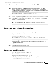
... Channel Port, page 3-7 Preparing for Network Connections When preparing your site for network connections to the Cisco UCS 6100 Series Fabric Interconnect, consider the following types of ports: • RS-232 port-create a local management connection. • Ethernet ports, encrypted and unencrypted-to connect to a LAN. • Fibre Channel ports-connect to the Console Port The console port is an RS-232 port with an RJ-45 interface. (See Figure 3-1.) The console port is an asynchronous (async) serial port; Send document comments...
... Channel Port, page 3-7 Preparing for Network Connections When preparing your site for network connections to the Cisco UCS 6100 Series Fabric Interconnect, consider the following types of ports: • RS-232 port-create a local management connection. • Ethernet ports, encrypted and unencrypted-to connect to a LAN. • Fibre Channel ports-connect to the Console Port The console port is an RS-232 port with an RJ-45 interface. (See Figure 3-1.) The console port is an asynchronous (async) serial port; Send document comments...

Hardware Installation Guide
Page 66
... 3-1 Connecting to the Console Port on a Cisco UCS 6120XP 192828 Figure 3-2 Connecting to the Console Port on the Cisco UCS 6120XP. Figure 3-1 shows how to connect to the console port on a Cisco UCS 6140XP 186705 You can use the console port to perform the following: • Configure the Cisco UCS 6100 Series Fabric Interconnect from the CLI. • Monitor network statistics and errors. • Configure SNMP agent parameters. • Download software updates. Connecting to the Console Port Chapter 3 Connecting the Cisco...
... 3-1 Connecting to the Console Port on a Cisco UCS 6120XP 192828 Figure 3-2 Connecting to the Console Port on the Cisco UCS 6120XP. Figure 3-1 shows how to connect to the console port on a Cisco UCS 6140XP 186705 You can use the console port to perform the following: • Configure the Cisco UCS 6100 Series Fabric Interconnect from the CLI. • Monitor network statistics and errors. • Configure SNMP agent parameters. • Download software updates. Connecting to the Console Port Chapter 3 Connecting the Cisco...
Hardware Installation Guide
Page 67
... Interconnect Hardware Installation Guide 3-3 Chapter 3 Connecting the Cisco UCS 6100 Series Fabric Interconnect Connecting to the Ethernet Connector Port Send document comments to ucs-docfeedback@cisco.com Note To connect the console port to an Ethernet port. This section includes the following default port characteristics: 9600 baud, 8 data bits, 1 stop bit, no parity. For configuration instructions, see the Cisco UCS Manager CLI Configuration Guide. The Ethernet connector port has an RJ-45 interface. Connecting to an Ethernet Port Use an SFP+ transceiver to connect...
... Interconnect Hardware Installation Guide 3-3 Chapter 3 Connecting the Cisco UCS 6100 Series Fabric Interconnect Connecting to the Ethernet Connector Port Send document comments to ucs-docfeedback@cisco.com Note To connect the console port to an Ethernet port. This section includes the following default port characteristics: 9600 baud, 8 data bits, 1 stop bit, no parity. For configuration instructions, see the Cisco UCS Manager CLI Configuration Guide. The Ethernet connector port has an RJ-45 interface. Connecting to an Ethernet Port Use an SFP+ transceiver to connect...

Hardware Installation Guide
Page 95
...-02 Cisco UCS 6100 Series Fabric Interconnect Hardware Installation Guide IN-3 Index Send document comments to ucs-docfeedback@cisco.com length B-3 supported power cords (figure) B-4 supported power cords (table) B-3 power plugs B-4 power supplies blank filler panel (figure) 1-16 description 1-14, 1-15 installing 2-25 LED descriptions 1-15 removing 2-24 power supply power supply output voltage A-2 pre-installation guidelines 2-2 options 2-2 unpacking the chassis 2-6 R rack 2-6, 2-8 rack-mount installation 2-7, 2-9 rack-mount kit contents 2-6, 2-8 records chassis serial number C-4 contact...
...-02 Cisco UCS 6100 Series Fabric Interconnect Hardware Installation Guide IN-3 Index Send document comments to ucs-docfeedback@cisco.com length B-3 supported power cords (figure) B-4 supported power cords (table) B-3 power plugs B-4 power supplies blank filler panel (figure) 1-16 description 1-14, 1-15 installing 2-25 LED descriptions 1-15 removing 2-24 power supply power supply output voltage A-2 pre-installation guidelines 2-2 options 2-2 unpacking the chassis 2-6 R rack 2-6, 2-8 rack-mount installation 2-7, 2-9 rack-mount kit contents 2-6, 2-8 records chassis serial number C-4 contact...


