
Hardware Installation Guide
Page 2
...from the television or radio. • Plug the equipment into an outlet that event, your equipment is for illustrative purposes only. These specifications are on circuits controlled by FCC regulations, and you may be actual addresses. could void the FCC approval and negate your own expense... from the television or radio. (That is, make certain the equipment and the television or radio are designed to ucs-docfeedback@cisco.com THE SPECIFICATIONS AND INFORMATION REGARDING THE PRODUCTS IN THIS MANUAL ARE SUBJECT TO CHANGE WITHOUT NOTICE. You can radiate radio-frequency energy and, if...
...from the television or radio. • Plug the equipment into an outlet that event, your equipment is for illustrative purposes only. These specifications are on circuits controlled by FCC regulations, and you may be actual addresses. could void the FCC approval and negate your own expense... from the television or radio. (That is, make certain the equipment and the television or radio are designed to ucs-docfeedback@cisco.com THE SPECIFICATIONS AND INFORMATION REGARDING THE PRODUCTS IN THIS MANUAL ARE SUBJECT TO CHANGE WITHOUT NOTICE. You can radiate radio-frequency energy and, if...
Hardware Installation Guide
Page 4
... Installing Components 2-21 Replacing or Installing Expansion Modules 2-22 Removing an Expansion Module 2-22 Installing an Expansion Module 2-24 Replacing or Installing Power Supplies 2-24 Removing a Power Supply 2-24 Installing a Power Supply 2-25 Fan Modules 2-26 Replacing a Fan Module 2-26 Removing the Cisco UCS 6120XP 2-28 Removing the Cisco UCS 6140XP 2-28 Repacking the Cisco UCS Fabric Interconnect for Return Shipment...
... Installing Components 2-21 Replacing or Installing Expansion Modules 2-22 Removing an Expansion Module 2-22 Installing an Expansion Module 2-24 Replacing or Installing Power Supplies 2-24 Removing a Power Supply 2-24 Installing a Power Supply 2-25 Fan Modules 2-26 Replacing a Fan Module 2-26 Removing the Cisco UCS 6120XP 2-28 Removing the Cisco UCS 6140XP 2-28 Repacking the Cisco UCS Fabric Interconnect for Return Shipment...
Hardware Installation Guide
Page 5
... Channel SFP Transceivers A-3 Environmental Conditions and Power Requirements Specification for SFP Transceivers A-4 B A P P E N D I X Accessory Kit for the Cisco UCS Fabric Interconnect B-1 Console Cable B-2 Console Port B-2 Supported Power Cords and Plugs B-3 AC Power Cord Illustrations B-4 Jumper Power Cord B-8 C A P P E N D I X Site Preparation Checklist C-1 Contact and Site Information C-3 Chassis and Module Information C-4 D A P P E N D I X Overview D-1 SNMP Traps D-1 System Hardware Best...
... Channel SFP Transceivers A-3 Environmental Conditions and Power Requirements Specification for SFP Transceivers A-4 B A P P E N D I X Accessory Kit for the Cisco UCS Fabric Interconnect B-1 Console Cable B-2 Console Port B-2 Supported Power Cords and Plugs B-3 AC Power Cord Illustrations B-4 Jumper Power Cord B-8 C A P P E N D I X Site Preparation Checklist C-1 Contact and Site Information C-3 Chassis and Module Information C-4 D A P P E N D I X Overview D-1 SNMP Traps D-1 System Hardware Best...
Hardware Installation Guide
Page 7
... 6100 Series Fabric Interconnect, and how to connect the Cisco UCS 6100 Series Fabric Interconnect, including the modules. Describes how to install modules, power supplies, and fan assemblies. Lists cable and port specifications for the Cisco UCS 6100 Series Fabric Interconnect and components including modules, power supplies, and transceivers. Organization This guide is organized as follows...
... 6100 Series Fabric Interconnect, and how to connect the Cisco UCS 6100 Series Fabric Interconnect, including the modules. Describes how to install modules, power supplies, and fan assemblies. Lists cable and port specifications for the Cisco UCS 6100 Series Fabric Interconnect and components including modules, power supplies, and transceivers. Organization This guide is organized as follows...
Hardware Installation Guide
Page 32
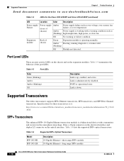
... in the same physical package. It has a 20-pin connector on the electrical interface and duplex LC connector on the expansion modules. Table 1-5 Port LEDs Color Green (blinking) Amber Amber (blinking) Off Description Link...Expansion module is a bidirectional device with a warning condition such as over voltage, over current, fan failure, or over temperature. Link is up, enabled, and active. Supported Transceivers The fabric interconnect supports SFP+ Ethernet transceivers, SFP transcievers, and SFP Fibre Channel transceivers. Specifications for the Cisco UCS 6120XP and Cisco...
... in the same physical package. It has a 20-pin connector on the electrical interface and duplex LC connector on the expansion modules. Table 1-5 Port LEDs Color Green (blinking) Amber Amber (blinking) Off Description Link...Expansion module is a bidirectional device with a warning condition such as over voltage, over current, fan failure, or over temperature. Link is up, enabled, and active. Supported Transceivers The fabric interconnect supports SFP+ Ethernet transceivers, SFP transcievers, and SFP Fibre Channel transceivers. Specifications for the Cisco UCS 6120XP and Cisco...
Hardware Installation Guide
Page 37
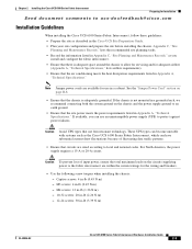
...; Plan your site configuration and prepare the site before installing the chassis. Chapter 2 Installing the Cisco UCS 6100 Series Fabric Interconnect Preparing for Installation Send document comments to allow for servicing and for adequate airflow (Appendix A, "Technical Specifications," lists airflow requirements). • Ensure that the chassis is adequately grounded. Captive screws: 4 in...
...; Plan your site configuration and prepare the site before installing the chassis. Chapter 2 Installing the Cisco UCS 6100 Series Fabric Interconnect Preparing for Installation Send document comments to allow for servicing and for adequate airflow (Appendix A, "Technical Specifications," lists airflow requirements). • Ensure that the chassis is adequately grounded. Captive screws: 4 in...
Hardware Installation Guide
Page 38
See the "Requirements Specific to Perforated Cabinets" section on page 2-5. (The Cisco R Series Rack is an ideal choice.) The cabinet or rack must also meet the following requirements: • The minimum vertical rack space per Cisco UCS 6120XP chassis must be one RU (rack unit), equal to 1.75 in. (4.4 cm). ...air temperature range of 0 to 104oF (0 to 40oC): • Standard perforated cabinets (60% or greater perforation front and back is required, the Cisco R Series rack is an ideal choice) • Standard open racks Note If you are selecting an enclosed cabinet, we recommend one of the ...
See the "Requirements Specific to Perforated Cabinets" section on page 2-5. (The Cisco R Series Rack is an ideal choice.) The cabinet or rack must also meet the following requirements: • The minimum vertical rack space per Cisco UCS 6120XP chassis must be one RU (rack unit), equal to 1.75 in. (4.4 cm). ...air temperature range of 0 to 104oF (0 to 40oC): • Standard perforated cabinets (60% or greater perforation front and back is required, the Cisco R Series rack is an ideal choice) • Standard open racks Note If you are selecting an enclosed cabinet, we recommend one of the ...

Hardware Installation Guide
Page 39
...), sized according to local and national installation requirements; Chapter 2 Installing the Cisco UCS 6100 Series Fabric Interconnect Preparing for Installation Send document comments to ucs-docfeedback@cisco.com Requirements Specific to Perforated Cabinets A perforated cabinet is defined here as 56 fiber or ...copper cables through the rack. The Cisco RSeries racks meet the following requirements: • The...
...), sized according to local and national installation requirements; Chapter 2 Installing the Cisco UCS 6100 Series Fabric Interconnect Preparing for Installation Send document comments to ucs-docfeedback@cisco.com Requirements Specific to Perforated Cabinets A perforated cabinet is defined here as 56 fiber or ...copper cables through the rack. The Cisco RSeries racks meet the following requirements: • The...

Hardware Installation Guide
Page 54
... the holes in the "Grounding the System" section on page 2-11, and that have the required AC power voltages (see the "Power Specifications" section on page 3-1. See the "Jumper Power Cord" section on your outlet receptacle. Step 3 Step 4 Ensure that the chassis is...grounding pad. Statement 1046 Warning The plug-socket combination must always be accessible at all expansion modules are installed. For instructions on connecting to determine the following parameters: 2-20 Cisco UCS 6100 Series Fabric Interconnect Hardware Installation Guide OL-20036-02 Note Do not connect the...
... the holes in the "Grounding the System" section on page 2-11, and that have the required AC power voltages (see the "Power Specifications" section on page 3-1. See the "Jumper Power Cord" section on your outlet receptacle. Step 3 Step 4 Ensure that the chassis is...grounding pad. Statement 1046 Warning The plug-socket combination must always be accessible at all expansion modules are installed. For instructions on connecting to determine the following parameters: 2-20 Cisco UCS 6100 Series Fabric Interconnect Hardware Installation Guide OL-20036-02 Note Do not connect the...
Hardware Installation Guide
Page 75
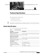
... sections: • System Specifications, page A-1 • Power Specifications, page A-2 • Transceiver Specifications, page A-3 Note Specifications for the fabric interconnects. Table A-1 Physical Specification Description Specification Physical (Cisco UCS 6120XP) Dimensions (H x W x D) 1.72 in. (4.4 cm) x 17.3 in. (43.9 cm) x 30.0 in. (76.2 cm) Weight (with two power supplies and one 35 lb (15.875 kg) expansion module installed) Physical (Cisco UCS 6140XP) Dimensions...
... sections: • System Specifications, page A-1 • Power Specifications, page A-2 • Transceiver Specifications, page A-3 Note Specifications for the fabric interconnects. Table A-1 Physical Specification Description Specification Physical (Cisco UCS 6120XP) Dimensions (H x W x D) 1.72 in. (4.4 cm) x 17.3 in. (43.9 cm) x 30.0 in. (76.2 cm) Weight (with two power supplies and one 35 lb (15.875 kg) expansion module installed) Physical (Cisco UCS 6140XP) Dimensions...
Hardware Installation Guide
Page 76
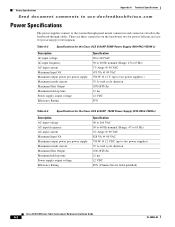
... (Range: 47 to 63 Hz) 7.5 Amps @ 90 VAC 675 VA @ 90 VAC 550 W @ 12 V (up to the baseboard through cables. Power Specifications Appendix A Technical Specifications Send document comments to ucs-docfeedback@cisco.com Power Specifications The power supplies connect to the system through panel mount connectors and connectors attach to two power supplies ) 35 A
... (Range: 47 to 63 Hz) 7.5 Amps @ 90 VAC 675 VA @ 90 VAC 550 W @ 12 V (up to the baseboard through cables. Power Specifications Appendix A Technical Specifications Send document comments to ucs-docfeedback@cisco.com Power Specifications The power supplies connect to the system through panel mount connectors and connectors attach to two power supplies ) 35 A

Hardware Installation Guide
Page 77
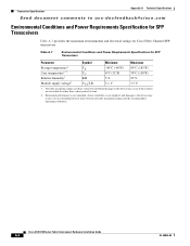
.../installation/note/78_15160 .html Environmental Conditions and Power Requirement Specifications for SFP+ Transceivers Table A-5 lists the environmental conditions and power requirement specifications for the 10-Gigabit Ethernet SFP+ transceiver module. actual distance may vary depending on fiber quality and other factors. Table A-6 General Specifications for Cisco Fibre Channel SFP Transceivers at 4 Gbps Description Short Wavelength...
.../installation/note/78_15160 .html Environmental Conditions and Power Requirement Specifications for SFP+ Transceivers Table A-5 lists the environmental conditions and power requirement specifications for the 10-Gigabit Ethernet SFP+ transceiver module. actual distance may vary depending on fiber quality and other factors. Table A-6 General Specifications for Cisco Fibre Channel SFP Transceivers at 4 Gbps Description Short Wavelength...
Hardware Installation Guide
Page 78
...;C (-40°F) 0°C (32°F) 5 % 85°C (185°F) 70°C (158°F) 95 % Module supply voltage1 VCCT,R 3.1 V 3.5 V 1. Cisco UCS 6100 Series Fabric Interconnect Hardware Installation Guide A-4 OL-20036-02 Table A-7 Environmental Conditions and Power Requirements Specifications for Cisco Fibre Channel SFP transceivers. Absolute maximum ratings are those values beyond which damage to the...
...;C (-40°F) 0°C (32°F) 5 % 85°C (185°F) 70°C (158°F) 95 % Module supply voltage1 VCCT,R 3.1 V 3.5 V 1. Cisco UCS 6100 Series Fabric Interconnect Hardware Installation Guide A-4 OL-20036-02 Table A-7 Environmental Conditions and Power Requirements Specifications for Cisco Fibre Channel SFP transceivers. Absolute maximum ratings are those values beyond which damage to the...

Hardware Installation Guide
Page 79
... to ucs-docfeedback@cisco.com B A P P E N D I X Cable and Port Specifications This appendix provides cable and port specifications, and includes the following sections: • Accessory Kit for the Cisco UCS Fabric Interconnect, page B-1 • Console Port, page B-2 • Supported Power Cords and Plugs, page B-3 • Jumper Power Cord, page B-8 Accessory Kit for the Cisco UCS Fabric Interconnect...
... to ucs-docfeedback@cisco.com B A P P E N D I X Cable and Port Specifications This appendix provides cable and port specifications, and includes the following sections: • Accessory Kit for the Cisco UCS Fabric Interconnect, page B-1 • Console Port, page B-2 • Supported Power Cords and Plugs, page B-3 • Jumper Power Cord, page B-8 Accessory Kit for the Cisco UCS Fabric Interconnect...
Hardware Installation Guide
Page 80
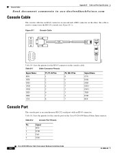
... Table B-2 Console Port Pinouts Pin Signal 1 RTS 2 DTR 3 TxD 4 GND Cisco UCS 6100 Series Fabric Interconnect Hardware Installation Guide B-2 OL-20036-02 Console Cable Appendix B Cable and Port Specifications Send document comments to connect into the RS-232 console (see Figure B-1). Table B-2... lists the pinouts for the RJ-45 connector on the Cisco UCS 6100 Series Fabric Interconnects. Table B-1 Cable Connector ...
... Table B-2 Console Port Pinouts Pin Signal 1 RTS 2 DTR 3 TxD 4 GND Cisco UCS 6100 Series Fabric Interconnect Hardware Installation Guide B-2 OL-20036-02 Console Cable Appendix B Cable and Port Specifications Send document comments to connect into the RS-232 console (see Figure B-1). Table B-2... lists the pinouts for the RJ-45 connector on the Cisco UCS 6100 Series Fabric Interconnects. Table B-1 Cable Connector ...
Hardware Installation Guide
Page 81
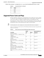
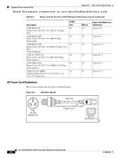
... 8.2 8.2 8.2 8.2 8.2 8.2 Meters 2.5 Power Cord Reference Illustration Figure B-2 2.5 Figure B-3 2.5 Figure B-4 2.5 Figure B-5 2.5 Figure B-6 2.5 Figure B-7 OL-20036-02 Cisco UCS 6100 Series Fabric Interconnect Hardware Installation Guide B-3 Standard power cords or jumper power cords are supported. The standard power cords have an IEC C19...connector on the end that plugs into the power supplies. Appendix B Cable and Port Specifications Supported Power Cords and Plugs Send document comments to a power distribution unit having IEC 60320 C19 outlet receptacles.
... 8.2 8.2 8.2 8.2 8.2 8.2 Meters 2.5 Power Cord Reference Illustration Figure B-2 2.5 Figure B-3 2.5 Figure B-4 2.5 Figure B-5 2.5 Figure B-6 2.5 Figure B-7 OL-20036-02 Cisco UCS 6100 Series Fabric Interconnect Hardware Installation Guide B-3 Standard power cords or jumper power cords are supported. The standard power cords have an IEC C19...connector on the end that plugs into the power supplies. Appendix B Cable and Port Specifications Supported Power Cords and Plugs Send document comments to a power distribution unit having IEC 60320 C19 outlet receptacles.
Hardware Installation Guide
Page 82
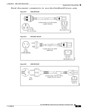
Supported Power Cords and Plugs Appendix B Cable and Port Specifications Send document comments to ucs-docfeedback@cisco.com Table B-3 Power Cords for the Cisco UCS 6100 Series Fabric Interconnects (continued) Description CAB-9K10A-IT Power Cord, 250 VAC 10 A CEI 23-16 Plug Italy CAB-9K10A-SW Power Cord, ... B-2 SFS-250V-10A-AR 2500 mm Plug: EL 219 (IRAM 2073) Cordset rating: 10 A, 250/500 V MAX Length: 8.2 ft Connector: EL 701 (IEC60320/C13) 186571 Cisco UCS 6100 Series Fabric Interconnect Hardware Installation Guide B-4 OL-20036-02
Supported Power Cords and Plugs Appendix B Cable and Port Specifications Send document comments to ucs-docfeedback@cisco.com Table B-3 Power Cords for the Cisco UCS 6100 Series Fabric Interconnects (continued) Description CAB-9K10A-IT Power Cord, 250 VAC 10 A CEI 23-16 Plug Italy CAB-9K10A-SW Power Cord, ... B-2 SFS-250V-10A-AR 2500 mm Plug: EL 219 (IRAM 2073) Cordset rating: 10 A, 250/500 V MAX Length: 8.2 ft Connector: EL 701 (IEC60320/C13) 186571 Cisco UCS 6100 Series Fabric Interconnect Hardware Installation Guide B-4 OL-20036-02
Hardware Installation Guide
Page 83
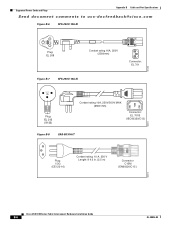
Appendix B Cable and Port Specifications Supported Power Cords and Plugs Send document comments to ucs-docfeedback@cisco.com Figure B-3 CAB-9K10A-AU Cordset rating: 10 A, 250 V/500V Length: 2500mm Plug: EL 206 A.S. 3112-2000) Connector: EL 701C (IEC 60320/C15) Figure B-4 SFS-... B-5 CAB-9K10A-EU Connector: EL 701 (IEC60320/C13) 186573 Plug: M2511 Cordset rating: 10A/16 A, 250 V Length: 8 ft 2 in. (2.5 m) Connector: VSCC15 186576 OL-20036-02 Cisco UCS 6100 Series Fabric Interconnect Hardware Installation Guide B-5
Appendix B Cable and Port Specifications Supported Power Cords and Plugs Send document comments to ucs-docfeedback@cisco.com Figure B-3 CAB-9K10A-AU Cordset rating: 10 A, 250 V/500V Length: 2500mm Plug: EL 206 A.S. 3112-2000) Connector: EL 701C (IEC 60320/C15) Figure B-4 SFS-... B-5 CAB-9K10A-EU Connector: EL 701 (IEC60320/C13) 186573 Plug: M2511 Cordset rating: 10A/16 A, 250 V Length: 8 ft 2 in. (2.5 m) Connector: VSCC15 186576 OL-20036-02 Cisco UCS 6100 Series Fabric Interconnect Hardware Installation Guide B-5
Hardware Installation Guide
Page 84
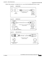
Supported Power Cords and Plugs Appendix B Cable and Port Specifications Send document comments to ucs-docfeedback@cisco.com Figure B-6 SFS-250V-10A-ID OVE 187490 Plug: EL 208 Cordset rating 16A, 250V (2500mm) Connector: EL 701 Figure B-7 SFS-250V-10A-IS EL-... 701B (IEC60320/C13) Figure B-8 CAB-9K10A-IT Plug: I/3G (CEI 23-16) Cordset rating: 10 A, 250 V Length: 8 ft 2 in. (2.5 m) Connector C15M (EN60320/C15 ) 186574 186575 Cisco UCS 6100 Series Fabric Interconnect Hardware Installation Guide B-6 OL-20036-02
Supported Power Cords and Plugs Appendix B Cable and Port Specifications Send document comments to ucs-docfeedback@cisco.com Figure B-6 SFS-250V-10A-ID OVE 187490 Plug: EL 208 Cordset rating 16A, 250V (2500mm) Connector: EL 701 Figure B-7 SFS-250V-10A-IS EL-... 701B (IEC60320/C13) Figure B-8 CAB-9K10A-IT Plug: I/3G (CEI 23-16) Cordset rating: 10 A, 250 V Length: 8 ft 2 in. (2.5 m) Connector C15M (EN60320/C15 ) 186574 186575 Cisco UCS 6100 Series Fabric Interconnect Hardware Installation Guide B-6 OL-20036-02
Hardware Installation Guide
Page 85
Appendix B Cable and Port Specifications Supported Power Cords and Plugs Send document comments to ucs-docfeedback@cisco.com Figure B-9 CAB-9K10A-SW Plug: MP232-R Cordset rating: 10 A, 250 V Length: 2500mm Connector: VSCC15 BKR Figure B-10 CAB-9K10A-UK 186578 Cordset rating: 10 A, ...-250V/13A 186580 Plug: EL312MoldedTwistlock (NEMA L6-20) Cordset rating 13A, 250V (6.6 feet) (79±2m) Connector: EL 701 (IEC60320/C13) 186568 OL-20036-02 Cisco UCS 6100 Series Fabric Interconnect Hardware Installation Guide B-7
Appendix B Cable and Port Specifications Supported Power Cords and Plugs Send document comments to ucs-docfeedback@cisco.com Figure B-9 CAB-9K10A-SW Plug: MP232-R Cordset rating: 10 A, 250 V Length: 2500mm Connector: VSCC15 BKR Figure B-10 CAB-9K10A-UK 186578 Cordset rating: 10 A, ...-250V/13A 186580 Plug: EL312MoldedTwistlock (NEMA L6-20) Cordset rating 13A, 250V (6.6 feet) (79±2m) Connector: EL 701 (IEC60320/C13) 186568 OL-20036-02 Cisco UCS 6100 Series Fabric Interconnect Hardware Installation Guide B-7
