Maintenance and Service Guide
Page 6
... module ...47 Hard drive ...48 Optical drive (select models only 51 Keyboard ...53 Top cover ...56 Power button board 60 TouchPad button board 61 Speakers ...63 USB board ...65 Power connector cable 66 Display assembly ...68 System board ...76 Optical drive connector cable 79 RTC battery ...81 Fan/heat sink assembly 83 Processor ...89 5 Setup Utility (BIOS) and System Diagnostics 92 Using Setup Utility ...92 Starting Setup Utility 92 Changing the language of Setup Utility 92 Navigating and selecting in Setup Utility 93 Displaying system information 93 Restoring factory settings...
... module ...47 Hard drive ...48 Optical drive (select models only 51 Keyboard ...53 Top cover ...56 Power button board 60 TouchPad button board 61 Speakers ...63 USB board ...65 Power connector cable 66 Display assembly ...68 System board ...76 Optical drive connector cable 79 RTC battery ...81 Fan/heat sink assembly 83 Processor ...89 5 Setup Utility (BIOS) and System Diagnostics 92 Using Setup Utility ...92 Starting Setup Utility 92 Changing the language of Setup Utility 92 Navigating and selecting in Setup Utility 93 Displaying system information 93 Restoring factory settings...
Maintenance and Service Guide
Page 13
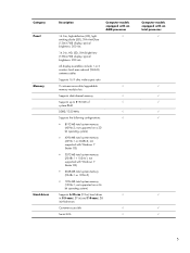
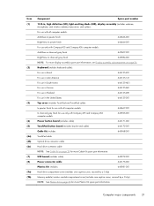
... (1366×768) display; typical brightness: 200 nits All display assemblies include 1 or 2 wireless local area network (WLAN) antenna cables Supports 16:9 ultra wide aspect ratio 2 customer-accessible/upgradable √ memory module slots Supports dual-channel memory √ Supports up to 8192 GB of √ system RAM DDR3/1333-MHz √ Supports the following configurations: √ ● 8192-MB total system memory (4096×2; not supported with Windows 7 Starter OS) ●...
... (1366×768) display; typical brightness: 200 nits All display assemblies include 1 or 2 wireless local area network (WLAN) antenna cables Supports 16:9 ultra wide aspect ratio 2 customer-accessible/upgradable √ memory module slots Supports dual-channel memory √ Supports up to 8192 GB of √ system RAM DDR3/1333-MHz √ Supports the following configurations: √ ● 8192-MB total system memory (4096×2; not supported with Windows 7 Starter OS) ●...
Maintenance and Service Guide
Page 23
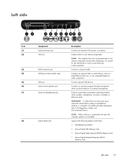
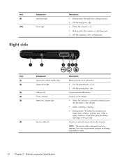
... the internal fan to the Regulatory, Safety, and Environmental Notices. NOTE: The computer fan starts up automatically to the jack, the computer speakers are disabled. To reduce the risk of personal injury, adjust the volume before putting on and off during routine operation. Left side Item (1) (2) (3) (4) (5) (6) (7) (8) Component External monitor port Vents (2) RJ-45 (network) jack HDMI port (select models only) USB port Audio-in (microphone) jack Audio-out (headphone) jack Digital Media Slot Description Connects an external VGA monitor...
... the internal fan to the Regulatory, Safety, and Environmental Notices. NOTE: The computer fan starts up automatically to the jack, the computer speakers are disabled. To reduce the risk of personal injury, adjust the volume before putting on and off during routine operation. Left side Item (1) (2) (3) (4) (5) (6) (7) (8) Component External monitor port Vents (2) RJ-45 (network) jack HDMI port (select models only) USB port Audio-in (microphone) jack Audio-out (headphone) jack Digital Media Slot Description Connects an external VGA monitor...
Maintenance and Service Guide
Page 24
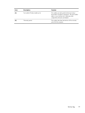
... battery light begins blinking rapidly. Connects an AC adapter. ● White: The computer is connected to external power and the battery is fully charged. ● Amber: A battery is charging. ● Blinking amber: The battery has reached a low battery level, or there is idle. Attaches an optional security cable to an optical disc. ● On: The optical drive is in Hibernation. Item (1) (2) (3) (4) (5) (6) Component Optical drive (select models only) Optical drive light USB ports (2) Power connector Battery/AC adapter light Security cable slot...
... battery light begins blinking rapidly. Connects an AC adapter. ● White: The computer is connected to external power and the battery is fully charged. ● Amber: A battery is charging. ● Blinking amber: The battery has reached a low battery level, or there is idle. Attaches an optional security cable to an optical disc. ● On: The optical drive is in Hibernation. Item (1) (2) (3) (4) (5) (6) Component Optical drive (select models only) Optical drive light USB ports (2) Power connector Battery/AC adapter light Security cable slot...
Maintenance and Service Guide
Page 27
Service tag 19 This number describes the duration of the warranty period for the computer. The part number helps a service technician to determine what components and parts are needed. Item (3) Description Part number/Product number (p/n) (4) Warranty period Function This number provides specific information about the product's hardware components.
Service tag 19 This number describes the duration of the warranty period for the computer. The part number helps a service technician to determine what components and parts are needed. Item (3) Description Part number/Product number (p/n) (4) Warranty period Function This number provides specific information about the product's hardware components.
Maintenance and Service Guide
Page 29
...-001 Top cover (includes TouchPad and TouchPad cable): In pewter finish for use with all computer models 646667-001 In charcoal gray finish for use only with Compaq 435 and Compaq 436 computer models 645963-001 Power button board (includes cable) 646171-001 TouchPad button board (includes bracket and cable) 646172-001 Cable Kit, includes: 645968-001 TouchPad cable Optical drive connector cable Hard drive connector cable NOTE: See Cable Kit on page 26. Keyboard (includes keyboard cable): For use in Brazil...
...-001 Top cover (includes TouchPad and TouchPad cable): In pewter finish for use with all computer models 646667-001 In charcoal gray finish for use only with Compaq 435 and Compaq 436 computer models 645963-001 Power button board (includes cable) 646171-001 TouchPad button board (includes bracket and cable) 646172-001 Cable Kit, includes: 645968-001 TouchPad cable Optical drive connector cable Hard drive connector cable NOTE: See Cable Kit on page 26. Keyboard (includes keyboard cable): For use in Brazil...
Maintenance and Service Guide
Page 32
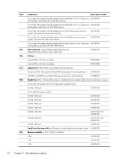
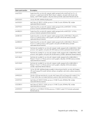
...-001 Hard drive (2.5-in, 7.0-mm, SATA; does not include hard drive connector cable, hard drive bracket, or screws): For use only with Compaq 435 and Compaq 436 computer models: 250-GB, 7200-rpm 649902-001 For use only with computer models equipped with an Intel Celeron or Core 2 processor 646184-001 and a graphics subsystem with UMA video memory Base enclosure (includes battery release latch, heat sink, replacement thermal...
...-001 Hard drive (2.5-in, 7.0-mm, SATA; does not include hard drive connector cable, hard drive bracket, or screws): For use only with Compaq 435 and Compaq 436 computer models: 250-GB, 7200-rpm 649902-001 For use only with computer models equipped with an Intel Celeron or Core 2 processor 646184-001 and a graphics subsystem with UMA video memory Base enclosure (includes battery release latch, heat sink, replacement thermal...
Maintenance and Service Guide
Page 43
..., Turion II, or V-Series processor and a graphics subsystem with discrete memory (includes replacement thermal material) 14.0-in, HD, LED, AntiGlare display assembly in charcoal gray finish for use only with Compaq 435 and Compaq 436 models (includes webcam, microphone, and wireless antenna transceivers and cables) 250-GB, 7200-rpm hard drive for use only with discrete video memory, and 512-MB of graphics subsystem memory (includes replacement thermal material) 14.0-in...
..., Turion II, or V-Series processor and a graphics subsystem with discrete memory (includes replacement thermal material) 14.0-in, HD, LED, AntiGlare display assembly in charcoal gray finish for use only with Compaq 435 and Compaq 436 models (includes webcam, microphone, and wireless antenna transceivers and cables) 250-GB, 7200-rpm hard drive for use only with discrete video memory, and 512-MB of graphics subsystem memory (includes replacement thermal material) 14.0-in...
Maintenance and Service Guide
Page 56
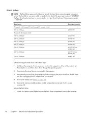
Description For use only with Compaq 435 and Compaq 436 computer models: 250-GB, 7200-rpm For use with all external devices connected to the computer. 48 Chapter 4 Removal and replacement procedures Remove the battery (see WLAN module on page 44). Shut down through the operating system. 2. Remove the hard drive: 1. If you are included in Hibernation, turn the computer on page 43). 5. Remove the memory module/wireless module compartment cover (see Battery on , and then shut...
Description For use only with Compaq 435 and Compaq 436 computer models: 250-GB, 7200-rpm For use with all external devices connected to the computer. 48 Chapter 4 Removal and replacement procedures Remove the battery (see WLAN module on page 44). Shut down through the operating system. 2. Remove the hard drive: 1. If you are included in Hibernation, turn the computer on page 43). 5. Remove the memory module/wireless module compartment cover (see Battery on , and then shut...
Maintenance and Service Guide
Page 59
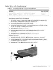
... external devices connected to release the optical drive tray from the optical drive. 3. Disconnect the power from the computer. 4. Remove the memory module/wireless module compartment cover (see Hard drive on , and then shut it out of the optical drive bay. Component replacement procedures 51 If you are unsure whether the computer is off or in Hibernation, turn the computer on page 48). Remove the hard drive compartment cover (see WLAN module...
... external devices connected to release the optical drive tray from the optical drive. 3. Disconnect the power from the computer. 4. Remove the memory module/wireless module compartment cover (see Hard drive on , and then shut it out of the optical drive bay. Component replacement procedures 51 If you are unsure whether the computer is off or in Hibernation, turn the computer on page 48). Remove the hard drive compartment cover (see WLAN module...
Maintenance and Service Guide
Page 100
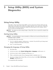
... as disk drives, display, keyboard, mouse, and printer). NOTE: Use extreme care when making changes in Setup Utility. Errors can be used with your change takes effect immediately. 92 Chapter 5 Setup Utility (BIOS) and System Diagnostics To start Setup Utility, follow these steps: 1. Use the arrow keys to select a language, and then press enter. 4. Starting Setup Utility NOTE: An external keyboard or mouse connected to a USB port can prevent the computer from operating properly. Changing the language of system and extended memory. Use the arrow keys...
... as disk drives, display, keyboard, mouse, and printer). NOTE: Use extreme care when making changes in Setup Utility. Errors can be used with your change takes effect immediately. 92 Chapter 5 Setup Utility (BIOS) and System Diagnostics To start Setup Utility, follow these steps: 1. Use the arrow keys to select a language, and then press enter. 4. Starting Setup Utility NOTE: An external keyboard or mouse connected to a USB port can prevent the computer from operating properly. Changing the language of system and extended memory. Use the arrow keys...

Maintenance and Service Guide
Page 101
... displayed. 3. or - Using Setup Utility 93 Turn on -screen instructions. - Your changes go into effect when the computer restarts. screen instructions. - Select the Main menu. To exit Setup Utility menus, choose one of the screen, or use a pointing device to click the item. ● To scroll up and down, click the up arrow key or the down arrow in Setup Utility, follow the on - Use the tab key and the arrow keys to enter Setup Utility...
... displayed. 3. or - Using Setup Utility 93 Turn on -screen instructions. - Your changes go into effect when the computer restarts. screen instructions. - Select the Main menu. To exit Setup Utility menus, choose one of the screen, or use a pointing device to click the item. ● To scroll up and down, click the up arrow key or the down arrow in Setup Utility, follow the on - Use the tab key and the arrow keys to enter Setup Utility...
Maintenance and Service Guide
Page 102
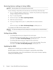
... in Setup Utility NOTE: Restoring defaults will not change the hard drive mode. NOTE: Your password settings and security settings are not visible, press esc to return to the values that were set at the bottom of the BIOS may be available on -screen instructions. 5. Then use the arrow keys to the menu display. Restoring factory settings in compressed files called SoftPaqs. Your changes go into effect when the computer restarts. Most BIOS updates on...
... in Setup Utility NOTE: Restoring defaults will not change the hard drive mode. NOTE: Your password settings and security settings are not visible, press esc to return to the values that were set at the bottom of the BIOS may be available on -screen instructions. 5. Then use the arrow keys to the menu display. Restoring factory settings in compressed files called SoftPaqs. Your changes go into effect when the computer restarts. Most BIOS updates on...
Maintenance and Service Guide
Page 103
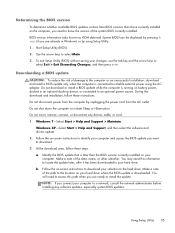
... initiate Sleep or Hibernation. You will need to know the version of the path to the location on -screen instructions to identify your hard drive where the BIOS update is connected to select Main. 3. At the download area, follow these steps: a. Make a note of the system BIOS currently installed. Using Setup Utility 95 Windows XP-Select Start > Help and Support, and then select the software and drivers update. 2. Make a note of damage to install the update. Downloading a BIOS update...
... initiate Sleep or Hibernation. You will need to know the version of the path to the location on -screen instructions to identify your hard drive where the BIOS update is connected to select Main. 3. At the download area, follow these steps: a. Make a note of the system BIOS currently installed. Using Setup Utility 95 Windows XP-Select Start > Help and Support, and then select the software and drivers update. 2. Make a note of damage to install the update. Downloading a BIOS update...
Maintenance and Service Guide
Page 104
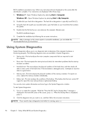
... the on -screen instructions. You can delete the downloaded file from your hard drive. To start -up test and checks for intermittent problems that the start System Diagnostics: 1. BIOS installation procedures vary. Follow any instructions that are displayed, follow the on -screen instructions. Windows 7-Open Windows Explorer by selecting Start > My Computer. 2. The BIOS installation begins. 5. If the test detects a damaged sector, it reports an error, replace the memory modules immediately. ● Battery test-This...
... the on -screen instructions. You can delete the downloaded file from your hard drive. To start -up test and checks for intermittent problems that the start System Diagnostics: 1. BIOS installation procedures vary. Follow any instructions that are displayed, follow the on -screen instructions. Windows 7-Open Windows Explorer by selecting Start > My Computer. 2. The BIOS installation begins. 5. If the test detects a damaged sector, it reports an error, replace the memory modules immediately. ● Battery test-This...
Maintenance and Service Guide
Page 108
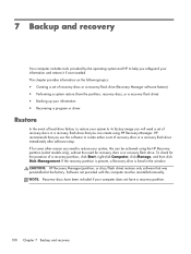
... recovery discs or a recovery flash drive immediately after software setup. If the recovery partition is present, a Recovery drive is listed in the window. To check for some other reason you need to restore your system, this computer must be achieved using HP Recovery Manager. HP recommends that you can be reinstalled manually. Software not provided with this can create using the HP Recovery partition (select models only), without the need a set of a recovery partition, click Start, right-click Computer, click Manage...
... recovery discs or a recovery flash drive immediately after software setup. If the recovery partition is present, a Recovery drive is listed in the window. To check for some other reason you need to restore your system, this computer must be achieved using HP Recovery Manager. HP recommends that you can be reinstalled manually. Software not provided with this can create using the HP Recovery partition (select models only), without the need a set of a recovery partition, click Start, right-click Computer, click Manage...
Maintenance and Service Guide
Page 109
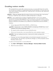
...one set of recovery discs or one set of recovery discs or a recovery flash drive: 1. Follow the on an external device, such as CD-RW, DVD±RW, and double-layer DVD±RW discs, are creating recovery discs, number each disc before you have finished creating the recovery discs or recovery flash drive. Select Start > All Programs > Recovery Manager > Recovery Media Creation. 2. Creating restore media HP recommends that you create either a set of recovery discs or a recovery flash drive to be connected directly to a USB port on the computer, not to a USB port on -screen instructions...
...one set of recovery discs or one set of recovery discs or a recovery flash drive: 1. Follow the on an external device, such as CD-RW, DVD±RW, and double-layer DVD±RW discs, are creating recovery discs, number each disc before you have finished creating the recovery discs or recovery flash drive. Select Start > All Programs > Recovery Manager > Recovery Media Creation. 2. Creating restore media HP recommends that you create either a set of recovery discs or a recovery flash drive to be connected directly to a USB port on the computer, not to a USB port on -screen instructions...
Maintenance and Service Guide
Page 123
... display panel cable removal 74 spare part number 27, 33, 74 Display Screw Kit, spare part number 27, 33 display specifications 98 display switch 10 drives, preventing damage 37 DVD±RW and CD-RW Super Multi Double-Layer Combo Drive precautions 37 removal 51 spare part number 24, 29, 33, 51 E electrostatic discharge 37 equipment guidelines 40 esc key 12 Ethernet, product description 6 external media cards, product description 7 external monitor port 15 F fan/heat sink assembly removal...
... display panel cable removal 74 spare part number 27, 33, 74 Display Screw Kit, spare part number 27, 33 display specifications 98 display switch 10 drives, preventing damage 37 DVD±RW and CD-RW Super Multi Double-Layer Combo Drive precautions 37 removal 51 spare part number 24, 29, 33, 51 E electrostatic discharge 37 equipment guidelines 40 esc key 12 Ethernet, product description 6 external media cards, product description 7 external monitor port 15 F fan/heat sink assembly removal...
Maintenance and Service Guide
Page 124
... Windows logo 12 L left-side components 15 light components 13 lights battery/AC adapter 16 caps lock 13 hard drive 16 optical drive 16 power 13, 16 TouchPad 13, 14 webcam 10 wireless 13 M mass storage device precautions 37 removal 48 spare part numbers 28, 48 memory module product description 5 removal 47 spare part numbers 24, 31, 32, 47 memory module compartment 17 memory module/wireless module compartment cover illustrated 30 removal 44 microphone location 11 product description 6 microphone jack 15 model name 1 monitor port 15 N network jack 15 O operating...
... Windows logo 12 L left-side components 15 light components 13 lights battery/AC adapter 16 caps lock 13 hard drive 16 optical drive 16 power 13, 16 TouchPad 13, 14 webcam 10 wireless 13 M mass storage device precautions 37 removal 48 spare part numbers 28, 48 memory module product description 5 removal 47 spare part numbers 24, 31, 32, 47 memory module compartment 17 memory module/wireless module compartment cover illustrated 30 removal 44 microphone location 11 product description 6 microphone jack 15 model name 1 monitor port 15 N network jack 15 O operating...
Maintenance and Service Guide
Page 125
...89 product description audio 6 chipset 3 display panel 5 Ethernet 6 external media cards 7 graphics 4 hard drives 5 keyboard 8 memory module 5 microphone 6 operating system 8 optical drive 6 pointing device 8 ports 7 power requirements 8 processors 1 product name 1 security 8 serviceability 9 video 6 wireless 7 product name 1, 41 product number 42 R removal/replacement preliminaries 36 procedures 41 right-side components RJ-45 jack 15 RTC battery removal 81 spare part number 16 22, 33, 81 serviceability, product description 9 Setup Utility (BIOS) 92 Speaker Kit, spare part number 22, 33, 63...
...89 product description audio 6 chipset 3 display panel 5 Ethernet 6 external media cards 7 graphics 4 hard drives 5 keyboard 8 memory module 5 microphone 6 operating system 8 optical drive 6 pointing device 8 ports 7 power requirements 8 processors 1 product name 1 security 8 serviceability 9 video 6 wireless 7 product name 1, 41 product number 42 R removal/replacement preliminaries 36 procedures 41 right-side components RJ-45 jack 15 RTC battery removal 81 spare part number 16 22, 33, 81 serviceability, product description 9 Setup Utility (BIOS) 92 Speaker Kit, spare part number 22, 33, 63...


