
Service Manual
Page 1
Website:http://biz.LGservice.com E-mail:http://www.LGEservice.com/techsup.html COLOR MONITOR SERVICE MANUAL CHASSIS NO. : CA-110 FACTORY MODEL: CQ771G MODEL: S7500 (PE1165T), S7500 (PE1165), MV7500 (PE1165U), MV7500 (PE1165), CV7500 (PE1165U) *( ) ID LABEL Model No. CAUTION BEFORE SERVICING THE UNIT, READ THE SAFETY PRECAUTIONS IN THIS MANUAL.
Website:http://biz.LGservice.com E-mail:http://www.LGEservice.com/techsup.html COLOR MONITOR SERVICE MANUAL CHASSIS NO. : CA-110 FACTORY MODEL: CQ771G MODEL: S7500 (PE1165T), S7500 (PE1165), MV7500 (PE1165U), MV7500 (PE1165), CV7500 (PE1165U) *( ) ID LABEL Model No. CAUTION BEFORE SERVICING THE UNIT, READ THE SAFETY PRECAUTIONS IN THIS MANUAL.
Service Manual
Page 3
... the original design without obtaining written permission from shock hazard during installation. SAFETY CHECK Care should be taken while servicing this color monitor which must be exercised is keep the high voltage at the factory recommended level. • If the meter indication exceeds the...be replaced with an integral implosion protection system, but care should be taken to the original lead dress specially in this color monitor because of X-radiation is essential to prevent Xradiation. The following safety checks and servicing guidelines. There are marked on the ...
... the original design without obtaining written permission from shock hazard during installation. SAFETY CHECK Care should be taken while servicing this color monitor which must be exercised is keep the high voltage at the factory recommended level. • If the meter indication exceeds the...be replaced with an integral implosion protection system, but care should be taken to the original lead dress specially in this color monitor because of X-radiation is essential to prevent Xradiation. The following safety checks and servicing guidelines. There are marked on the ...
Service Manual
Page 5
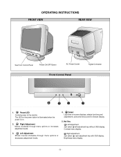
Brightness menu display. -5- Right Adjustment Moves clockwise through menu options or decreases adjustment levels. 4. Power/LED Controls power to the monitor. Left Adjustment Moves counter-clockwise through menu options or increases adjustment levels. 3. Right adjuatment Just select right adjustment key with OSD display. Contrast menu display. ...
Brightness menu display. -5- Right Adjustment Moves clockwise through menu options or decreases adjustment levels. 4. Power/LED Controls power to the monitor. Left Adjustment Moves counter-clockwise through menu options or increases adjustment levels. 3. Right adjuatment Just select right adjustment key with OSD display. Contrast menu display. ...
Service Manual
Page 8
...(T901). 5) These secondary voltages are rectified by each mode is applied to the primary coil of the FBT and it to say, this monitor flowing out through the power input line. This circuit takes the horizontal and the vertical parabola waves from the signal cable. 2) The Micom(IC401... controlled data. (H-size, H-position, V-size, ... A boosted voltage(about 25.5KV) appears at the secondary coils of power input line flowing into the monitor and/or some noise generated in the CRT during turning on and off mode. This circuit takes the vertical ramp wave from the SignalCable.
...(T901). 5) These secondary voltages are rectified by each mode is applied to the primary coil of the FBT and it to say, this monitor flowing out through the power input line. This circuit takes the horizontal and the vertical parabola waves from the signal cable. 2) The Micom(IC401... controlled data. (H-size, H-position, V-size, ... A boosted voltage(about 25.5KV) appears at the secondary coils of power input line flowing into the monitor and/or some noise generated in the CRT during turning on and off mode. This circuit takes the vertical ramp wave from the SignalCable.
Service Manual
Page 10
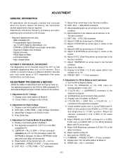
...procedure unless the EEPROM is changed. command. - 10 - ADJUSTMENT GENERAL INFORMATION All adjustment are thoroughly checked and corrected when the monitor leaves the factory, but sometimes several adjustments may be the best condition. 10) Adjust balance of the raster luminance. 10) ... when turn on the IBM compatible PC. 3) EEPROM → ALL CLEAR → Y(Yes) command. Do not run the alignment program on the monitor. Digital Voltmeter. - IBM compatible PC. - Adjustment for B+ Voltage. 1) Display cross hatch pattern at Mode 8. 2) Check C999 (+) voltage to ...
...procedure unless the EEPROM is changed. command. - 10 - ADJUSTMENT GENERAL INFORMATION All adjustment are thoroughly checked and corrected when the monitor leaves the factory, but sometimes several adjustments may be the best condition. 10) Adjust balance of the raster luminance. 10) ... when turn on the IBM compatible PC. 3) EEPROM → ALL CLEAR → Y(Yes) command. Do not run the alignment program on the monitor. Digital Voltmeter. - IBM compatible PC. - Adjustment for B+ Voltage. 1) Display cross hatch pattern at Mode 8. 2) Check C999 (+) voltage to ...
Service Manual
Page 11
... CDT at DRIVE of the luminance at Mode 8. 2) EEPROM → Write EDID command and confirm "EDID Write OK!!" Adjustment for EDID data save. 6. message of monitor. 3) Exit from the alignment program. 4) Power switch OFF/ON for Focus. 1) Set the Brightness and Contrast to max position. 2) Display cross hatch with quadrant text...
... CDT at DRIVE of the luminance at Mode 8. 2) EEPROM → Write EDID command and confirm "EDID Write OK!!" Adjustment for EDID data save. 6. message of monitor. 3) Exit from the alignment program. 4) Power switch OFF/ON for Focus. 1) Set the Brightness and Contrast to max position. 2) Display cross hatch with quadrant text...

Service Guide
Page 1
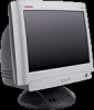
Service Manual 17-inch Color Monitor S7500/MV7500/CV7500
Service Manual 17-inch Color Monitor S7500/MV7500/CV7500
Service Guide
Page 4
... such as electrical shock and X-rays. 1-1 Safety Precautions 1-1-1 Warnings 1. High voltageshould always be corrected immediately. Operation of the monitor outside its cabinet or with at the ste ps fo r AC v olta ge measurements foreach exposedmetal part. Only when high ...necessary safety precautions and proceduresfor working onhighvoltage equipment. 3. Measure the AC voltage across the combination of the CRT or high voltage circuitry. 5. HP S7500/MV7500/CV7500 1 Precautions Follow these safety and servicing precautions to prevent damage and to modify thecircuit board,and...
... such as electrical shock and X-rays. 1-1 Safety Precautions 1-1-1 Warnings 1. High voltageshould always be corrected immediately. Operation of the monitor outside its cabinet or with at the ste ps fo r AC v olta ge measurements foreach exposedmetal part. Only when high ...necessary safety precautions and proceduresfor working onhighvoltage equipment. 3. Measure the AC voltage across the combination of the CRT or high voltage circuitry. 5. HP S7500/MV7500/CV7500 1 Precautions Follow these safety and servicing precautions to prevent damage and to modify thecircuit board,and...
Service Guide
Page 5
..., readand followthe SafetyPrecautions section ofthis manual. When replacing parts or circuit boards, clamp the lead wires around the component before the monitor is working properly, the Hi-Pot & Ground Continuity tests MUST BE performed before soldering. 4. b) Put the power switch of...3. Alwaysunplug theAC powercord fromthe AC power source before connecting the positive lead;always remove the instrument'sground lead last. HP S7500/MV7500/CV7500 1-1-3 Product Safety Notices Many electrical and mechanical parts in this manual. Always connect a test instrument's ground lead to 3 mA ...
..., readand followthe SafetyPrecautions section ofthis manual. When replacing parts or circuit boards, clamp the lead wires around the component before the monitor is working properly, the Hi-Pot & Ground Continuity tests MUST BE performed before soldering. 4. b) Put the power switch of...3. Alwaysunplug theAC powercord fromthe AC power source before connecting the positive lead;always remove the instrument'sground lead last. HP S7500/MV7500/CV7500 1-1-3 Product Safety Notices Many electrical and mechanical parts in this manual. Always connect a test instrument's ground lead to 3 mA ...
Service Guide
Page 6
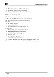
... the resistance value must be calibrated in regular period. 2. TestEquipment AC low ohm tester TOS-6100 or equivalent approved equipment. Test Procedure a) Plug the monitor power cord to touch the metal portion of the signal cable head during testing. Note : The test equipment must be less than 0.1 ohm. 3. ...indicator or beeper. If red light shows up , means test OK. Note : Be sure not to the tester terminals. Page 4 e) Turn on monitor power and tester power. d) Press "Test" button. HP S7500/MV7500/CV7500 d) Plug monitor power cord to the Hi Pot tester terminals.
... the resistance value must be calibrated in regular period. 2. TestEquipment AC low ohm tester TOS-6100 or equivalent approved equipment. Test Procedure a) Plug the monitor power cord to touch the metal portion of the signal cable head during testing. Note : The test equipment must be less than 0.1 ohm. 3. ...indicator or beeper. If red light shows up , means test OK. Note : Be sure not to the tester terminals. Page 4 e) Turn on monitor power and tester power. d) Press "Test" button. HP S7500/MV7500/CV7500 d) Plug monitor power cord to the Hi Pot tester terminals.
Service Guide
Page 10
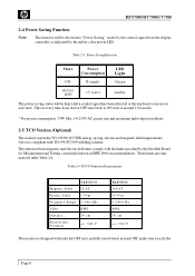
Power Saving Function State Power Consumption LED Light ON N o r m a l* Green Active OFF Table 2-3. HP S7500/MV7500/CV7500 2-4 Power Saving Function Note: The monitor will be driven into "Power Saving" mode by the control signal from the display controller, as indicated by the amber-color power LED.
Power Saving Function State Power Consumption LED Light ON N o r m a l* Green Active OFF Table 2-3. HP S7500/MV7500/CV7500 2-4 Power Saving Function Note: The monitor will be driven into "Power Saving" mode by the control signal from the display controller, as indicated by the amber-color power LED.
Service Guide
Page 11
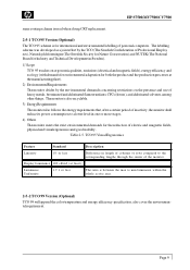
HP S7500/MV7500/CV7500 same routingscheme isused when doing CRT replacement. 2-5-1 TCO95 Version (Optional) The TCO 95 scheme is for international and environmental labelling of electric and magnetic fields, physicaland ...for the reduction of personal computers. TCO95 Visual Ergonomics Feature Standard Description Linearity 1% or less Difference in one or more stages. 4) Others The monitor meets the strict environmental demands for environmental adaptationfor both theproduct and the productionprocesses at least) Luminance Uniformity 1.7:1 or less The ratio is also recyclable...
HP S7500/MV7500/CV7500 same routingscheme isused when doing CRT replacement. 2-5-1 TCO95 Version (Optional) The TCO 95 scheme is for international and environmental labelling of electric and magnetic fields, physicaland ...for the reduction of personal computers. TCO95 Visual Ergonomics Feature Standard Description Linearity 1% or less Difference in one or more stages. 4) Others The monitor meets the strict environmental demands for environmental adaptationfor both theproduct and the productionprocesses at least) Luminance Uniformity 1.7:1 or less The ratio is also recyclable...
Service Guide
Page 12
...to device 4841 and some DAC in CPU, above operation takes about500 ms. 2. HP S7500/MV7500/CV7500 3 Operation Theory This is a fully digital controlled multi-sync color monitor that has I2C BUS controlled geometric correction, contrast and brightness-- that is TDA4841. 2. offers... the functions for key detection saving I /P and O/P, (b) Mute, (c) Power saving - factory adjust, (f) Pincushion's V. This monitor uses NOVA NT6865 CPU. It contains a 8051 8-bit CPU core, 512 bytes of MASK ROM, 10-channel 8 bit PWM D/A converter, 4channel A/D converters for...
...to device 4841 and some DAC in CPU, above operation takes about500 ms. 2. HP S7500/MV7500/CV7500 3 Operation Theory This is a fully digital controlled multi-sync color monitor that has I2C BUS controlled geometric correction, contrast and brightness-- that is TDA4841. 2. offers... the functions for key detection saving I /P and O/P, (b) Mute, (c) Power saving - factory adjust, (f) Pincushion's V. This monitor uses NOVA NT6865 CPU. It contains a 8051 8-bit CPU core, 512 bytes of MASK ROM, 10-channel 8 bit PWM D/A converter, 4channel A/D converters for...
Service Guide
Page 16
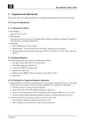
... procedures are necessary for about 15 minutes. 2. Page 14 HP S7500/MV7500/CV7500 4 Alignments and Adjustments This section of the service manual explains how to make permanent adjustments to the monitor settings. 4-1 General Adjustments 4-1-1 AdjustmentConditions a) PowerSupply Apply AC 115 ... Volt-ohm-A meter (SanwaFD-750C or equivalent) 2. 30 kVhigh voltage probe (HP34111A) 3. Allow the monitor towarm-up timefor convergence adjustment. Connect a DC voltage meter to the monitor. 3. b. Press both 1 key and 2 key simultaneously then power ON. 2. Synchronization: Horizontal and ...
... procedures are necessary for about 15 minutes. 2. Page 14 HP S7500/MV7500/CV7500 4 Alignments and Adjustments This section of the service manual explains how to make permanent adjustments to the monitor settings. 4-1 General Adjustments 4-1-1 AdjustmentConditions a) PowerSupply Apply AC 115 ... Volt-ohm-A meter (SanwaFD-750C or equivalent) 2. 30 kVhigh voltage probe (HP34111A) 3. Allow the monitor towarm-up timefor convergence adjustment. Connect a DC voltage meter to the monitor. 3. b. Press both 1 key and 2 key simultaneously then power ON. 2. Synchronization: Horizontal and ...
Service Guide
Page 18
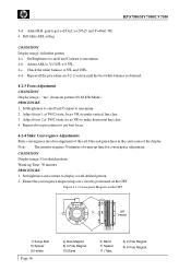
Check the white balance at T402 (static focus VR) to make vertical line clear. 3. Note : The monitor requires 30 minutes of the display. Convergence Magnets on the CRT. Adjust focus 2 at 5FL and 28FL. 4-d. Repeat above procedures to display a well-defined pattern. 2. Set ... + CRT FRONT P 1) Setup Bolt 5) Spacer 9) Holder Page 16 10 9 8 76 5 4 3 2 2) Bow Magnet 6) 4-Pole Magnet 10) Band 3) Band 7) Spacer 11) Tabs 4) 2-Pole Magnet 8) 6-Pole Magnet HP S7500/MV7500/CV7500 3-d Adjust R.B. Set Brightness to cutoff and Contrast to make horizontal line clear. 4. gain toget x=283...
Check the white balance at T402 (static focus VR) to make vertical line clear. 3. Note : The monitor requires 30 minutes of the display. Convergence Magnets on the CRT. Adjust focus 2 at 5FL and 28FL. 4-d. Repeat above procedures to display a well-defined pattern. 2. Set ... + CRT FRONT P 1) Setup Bolt 5) Spacer 9) Holder Page 16 10 9 8 76 5 4 3 2 2) Bow Magnet 6) 4-Pole Magnet 10) Band 3) Band 7) Spacer 11) Tabs 4) 2-Pole Magnet 8) 6-Pole Magnet HP S7500/MV7500/CV7500 3-d Adjust R.B. Set Brightness to cutoff and Contrast to make horizontal line clear. 4. gain toget x=283...
Service Guide
Page 19
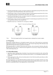
...and green lines. 6. Slowly rotate and move the coil away from the monitor. For proper degaussing,it is essential that is activated when the power is required when poor color impurity appears on the CRT will be noticeable. Page 17 Figure4-2. 4-pole and 6-poleMagnets Movement Blue Red...thehorizontal red, blue andgreen lines. 7. Should any part of the tube. HP S7500/MV7500/CV7500 3. Rotate the pair of rings of the screen. 5. The automatic degaussing will be fully functional again after the monitor has been in a rotary motionover the front, sides, and top of the ...
...and green lines. 6. Slowly rotate and move the coil away from the monitor. For proper degaussing,it is essential that is activated when the power is required when poor color impurity appears on the CRT will be noticeable. Page 17 Figure4-2. 4-pole and 6-poleMagnets Movement Blue Red...thehorizontal red, blue andgreen lines. 7. Should any part of the tube. HP S7500/MV7500/CV7500 3. Rotate the pair of rings of the screen. 5. The automatic degaussing will be fully functional again after the monitor has been in a rotary motionover the front, sides, and top of the ...


