
Maintenance and Service Guide
Page 3
... ...1-18 Internal Design...1-24 Removal and Replacement 2-1 Disassembly Flowchart ...2-3 Removing the Battery ...2-4 Removing an SDRAM Module...2-5 Removing the Wireless LAN Mini PCI Card 2-7 Removing the Hard Disk Drive...2-9 Recovering the Factory Software...2-11 Replacing Small Parts ...2-12 Removing the Keyboard Cover...2-13 Removing the Speaker Assembly ...2-15 Removing the Keyboard ...2-16 Removing the Switchboard PCA ...2-19 Removing the CD/DVD Drive...
... ...1-18 Internal Design...1-24 Removal and Replacement 2-1 Disassembly Flowchart ...2-3 Removing the Battery ...2-4 Removing an SDRAM Module...2-5 Removing the Wireless LAN Mini PCI Card 2-7 Removing the Hard Disk Drive...2-9 Recovering the Factory Software...2-11 Replacing Small Parts ...2-12 Removing the Keyboard Cover...2-13 Removing the Speaker Assembly ...2-15 Removing the Keyboard ...2-16 Removing the Switchboard PCA ...2-19 Removing the CD/DVD Drive...

Maintenance and Service Guide
Page 4
...Figure 2-30. Removing the Battery ...2-4 Figure 2-3. Removing the Mini PCI Card 2-7 Figure 2-6. Removing the Keyboard Cover 2-14 Figure 2-10. Removing the Top Case...2-31 Figure 2-22. Removing the Hard Disk Drive Guide 2-53 iv Service Manual Bottom View...1-10 Figure 1-4. Removing an SDRAM ...2-32 Removing the CPU Module 2-39 Figure 2-33. Removing the Keyboard ...2-17 Figure 2-13. Removing the CD/DVD Drive 2-22 Figure 2-17. Resetting the Notebook ...1-17 Figure 1-8. Replaceable Module Diagram 1-24 Figure 2-1. Removing the Floppy Drive 2-33 Figure 2-23. Removing the...
...Figure 2-30. Removing the Battery ...2-4 Figure 2-3. Removing the Mini PCI Card 2-7 Figure 2-6. Removing the Keyboard Cover 2-14 Figure 2-10. Removing the Top Case...2-31 Figure 2-22. Removing the Hard Disk Drive Guide 2-53 iv Service Manual Bottom View...1-10 Figure 1-4. Removing an SDRAM ...2-32 Removing the CPU Module 2-39 Figure 2-33. Removing the Keyboard ...2-17 Figure 2-13. Removing the CD/DVD Drive 2-22 Figure 2-17. Resetting the Notebook ...1-17 Figure 1-8. Replaceable Module Diagram 1-24 Figure 2-1. Removing the Floppy Drive 2-33 Figure 2-23. Removing the...

Maintenance and Service Guide
Page 31
The items marked by • in the following table are displayed throughout this chapter to remove and replace the notebook's components and assemblies. Removal Cross-Reference Assembly, display (page 2-23) • Assembly, speaker (page 2-15) • Battery, main (page 2-4) • Card, wireless LAN Mini PCI (page 2-7) Case, ... an M2.5×4.0mm T-head screw). Without proper grounding, an electrostatic discharge can damage the notebook. (The symbol at the end of the removal steps. Symbols like these to verify the sizes of screws before you how to show approximate full...
The items marked by • in the following table are displayed throughout this chapter to remove and replace the notebook's components and assemblies. Removal Cross-Reference Assembly, display (page 2-23) • Assembly, speaker (page 2-15) • Battery, main (page 2-4) • Card, wireless LAN Mini PCI (page 2-7) Case, ... an M2.5×4.0mm T-head screw). Without proper grounding, an electrostatic discharge can damage the notebook. (The symbol at the end of the removal steps. Symbols like these to verify the sizes of screws before you how to show approximate full...

Maintenance and Service Guide
Page 34
Figure 2-2. Removing the Battery (User-Replaceable) Required Equipment None Removal Procedure Slide the battery's release latch, and then pull the battery out of its compartment. Removing the Battery 2-4 Removal and Replacement Service Manual
Figure 2-2. Removing the Battery (User-Replaceable) Required Equipment None Removal Procedure Slide the battery's release latch, and then pull the battery out of its compartment. Removing the Battery 2-4 Removal and Replacement Service Manual

Maintenance and Service Guide
Page 35
... Module HP Pavilion 4x00, HP Compaq nx9005 and nx9000, Compaq Evo Notebook N1050v and N1010v, and Compaq Presario 2100 and 1100 Models Removal and Replacement 2-5 NOTE: HP Pavilion ze5300, ze5200, ze4300, ze4200, and ze4100, HP Compaq nx9010, nx9005 and nx9000, Compaq Evo Notebook N1050v and N1010v, and Compaq Presario 2500, 2100, and 1100 notebooks use only DDR266 SDRAM modules. Removing an SDRAM Module (User-Replaceable...
... Module HP Pavilion 4x00, HP Compaq nx9005 and nx9000, Compaq Evo Notebook N1050v and N1010v, and Compaq Presario 2100 and 1100 Models Removal and Replacement 2-5 NOTE: HP Pavilion ze5300, ze5200, ze4300, ze4200, and ze4100, HP Compaq nx9010, nx9005 and nx9000, Compaq Evo Notebook N1050v and N1010v, and Compaq Presario 2500, 2100, and 1100 notebooks use only DDR266 SDRAM modules. Removing an SDRAM Module (User-Replaceable...

Maintenance and Service Guide
Page 37
...Unplug the AC adapter, if present, and then remove the battery. 2. On the bottom of the connector. Press outward on the bottom of the notebook. Carefully pull the Mini PCI card out of the notebook, loosen the captive screws holding the Mini PCI door, and then remove the door. Figure 2-5. Disconnect the 2 antenna ... PCI door on the latches at the sides of the Mini PCI card to release it (the Mini PCI card pops up). 5. Removing the Mini PCI Card HP Pavilion ze4x00, HP Compaq nx9005 and nx9000, Compaq Evo Notebook N1050v and N1010v, and Compaq Presario 2100 and 1100 Models Service Manual...
...Unplug the AC adapter, if present, and then remove the battery. 2. On the bottom of the connector. Press outward on the bottom of the notebook. Carefully pull the Mini PCI card out of the notebook, loosen the captive screws holding the Mini PCI door, and then remove the door. Figure 2-5. Disconnect the 2 antenna ... PCI door on the latches at the sides of the Mini PCI card to release it (the Mini PCI card pops up). 5. Removing the Mini PCI Card HP Pavilion ze4x00, HP Compaq nx9005 and nx9000, Compaq Evo Notebook N1050v and N1010v, and Compaq Presario 2100 and 1100 Models Service Manual...

Maintenance and Service Guide
Page 39
... Disk Drive Service Manual Removal and Replacement 2-9 Figure 2-7. Removing the Hard Disk Drive (User-Replaceable) Required Equipment 1 Phillips screwdriver Removal Procedure NOTE: If you are installing a new hard disk drive, load the factory software and operating system on the drive as described ...as shown on the next page. 1. On the bottom of the notebook, remove the hard disk drive rubber screw plugs and M2.5×6.0mm screws. (The number of the notebook. Unplug the AC adapter, if present, and then remove the battery. 2. Carefully pull the hard disk drive out of plugs and screws ...
... Disk Drive Service Manual Removal and Replacement 2-9 Figure 2-7. Removing the Hard Disk Drive (User-Replaceable) Required Equipment 1 Phillips screwdriver Removal Procedure NOTE: If you are installing a new hard disk drive, load the factory software and operating system on the drive as described ...as shown on the next page. 1. On the bottom of the notebook, remove the hard disk drive rubber screw plugs and M2.5×6.0mm screws. (The number of the notebook. Unplug the AC adapter, if present, and then remove the battery. 2. Carefully pull the hard disk drive out of plugs and screws ...

Maintenance and Service Guide
Page 43
... PCA that secure the keyboard cover to damage the plastics or wireless antenna underneath. Service Manual Removal and Replacement 2-13 Gently pry up the center of the notebook. 3. Unplug the AC adapter, if present, and then remove the battery. 2. Carefully insert a flat-blade screwdriver blade under the keyboard cover near the right end, then...
... PCA that secure the keyboard cover to damage the plastics or wireless antenna underneath. Service Manual Removal and Replacement 2-13 Gently pry up the center of the notebook. 3. Unplug the AC adapter, if present, and then remove the battery. 2. Carefully insert a flat-blade screwdriver blade under the keyboard cover near the right end, then...

Maintenance and Service Guide
Page 45
... HP Pavilion ze5x00, HP Compaq nx9010 and nx9008, and Compaq Presario 2500 Series notebook speakers are integrated into the top case. Removing the Speaker Assembly (User-Replaceable) NOTE: The following speaker assembly removal procedures apply only to HP Pavilion 4x00, HP Compaq nx9005 and nx9000, Compaq Evo Notebook N1050v and N1010v, and Compaq Presario 2100 and 1100 Series notebooks. Removing the Speaker Assembly Service...
... HP Pavilion ze5x00, HP Compaq nx9010 and nx9008, and Compaq Presario 2500 Series notebook speakers are integrated into the top case. Removing the Speaker Assembly (User-Replaceable) NOTE: The following speaker assembly removal procedures apply only to HP Pavilion 4x00, HP Compaq nx9005 and nx9000, Compaq Evo Notebook N1050v and N1010v, and Compaq Presario 2100 and 1100 Series notebooks. Removing the Speaker Assembly Service...

Maintenance and Service Guide
Page 46
... CAUTION: Do not excessively bend or fold the keyboard cable. Unplug the AC adapter, if present, and then remove the battery. 2. Remove the keyboard cover (page 2-13). 3. Removing the Keyboard Required Equipment 1 Phillips screwdriver Removal Procedure 1. Remove the four M2.5×4.0mm screws that secure the keyboard to release the tabs from the top case. 5. Excessive... face down on the top case, forward of the keyboard into their slots in the top case, and then lower the keyboard into place. 2-16 Removal and Replacement Service Manual
... CAUTION: Do not excessively bend or fold the keyboard cable. Unplug the AC adapter, if present, and then remove the battery. 2. Remove the keyboard cover (page 2-13). 3. Removing the Keyboard Required Equipment 1 Phillips screwdriver Removal Procedure 1. Remove the four M2.5×4.0mm screws that secure the keyboard to release the tabs from the top case. 5. Excessive... face down on the top case, forward of the keyboard into their slots in the top case, and then lower the keyboard into place. 2-16 Removal and Replacement Service Manual
Maintenance and Service Guide
Page 48
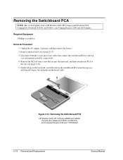
... the switchboard PCA to the top case (page 2-16). 5. Removing the Switchboard PCA HP Pavilion 4x00, HP Compaq nx9005 and nx9000, Compaq Evo Notebook N1050v and N1010v, and Compaq Presario 2100 and 1100 Models 2-18 Removal and Replacement Service Manual Unplug the AC adapter, if present, and then remove the battery. 2. Disconnect both the 2-wire and 4-wire cables that secures...
... the switchboard PCA to the top case (page 2-16). 5. Removing the Switchboard PCA HP Pavilion 4x00, HP Compaq nx9005 and nx9000, Compaq Evo Notebook N1050v and N1010v, and Compaq Presario 2100 and 1100 Models 2-18 Removal and Replacement Service Manual Unplug the AC adapter, if present, and then remove the battery. 2. Disconnect both the 2-wire and 4-wire cables that secures...

Maintenance and Service Guide
Page 49
...of the switchboard PCA to HP Pavilion 5x00, HP Compaq nx9010 and nx9008, and Compaq Presario 2500 models. Remove the keyboard cover (page 2-13). 3. Remove the two M2.5×4.0mm screws that connects the ...switchboard PCA to the top case. 5. Required Equipment 1 Phillips screwdriver Removal Procedure 1. NOTE: This section applies only to disconnect the PCA from the motherboard. 6. Unplug the AC adapter, if present, and then remove the battery...
...of the switchboard PCA to HP Pavilion 5x00, HP Compaq nx9010 and nx9008, and Compaq Presario 2500 models. Remove the keyboard cover (page 2-13). 3. Remove the two M2.5×4.0mm screws that connects the ...switchboard PCA to the top case. 5. Required Equipment 1 Phillips screwdriver Removal Procedure 1. NOTE: This section applies only to disconnect the PCA from the motherboard. 6. Unplug the AC adapter, if present, and then remove the battery...

Maintenance and Service Guide
Page 50
... the correct locations when reinstalling the CD/DVD drive. 4. Removing the CD/DVD Drive HP Pavilion 4x00, HP Compaq nx9005 and nx9000, Compaq Evo Notebook N1050v and N1010v, and Compaq Presario 2100 and 1100 Models 2-20 Removal and Replacement Service Manual Unplug the AC adapter, if present, and then remove the battery. 2. The back screw is a M2.5×6.0mm screw...
... the correct locations when reinstalling the CD/DVD drive. 4. Removing the CD/DVD Drive HP Pavilion 4x00, HP Compaq nx9005 and nx9000, Compaq Evo Notebook N1050v and N1010v, and Compaq Presario 2100 and 1100 Models 2-20 Removal and Replacement Service Manual Unplug the AC adapter, if present, and then remove the battery. 2. The back screw is a M2.5×6.0mm screw...

Maintenance and Service Guide
Page 51
Required Equipment 1 Phillips screwdriver Removal Procedure 1. Unplug the AC adapter, if present, and then remove the battery. 2. Remove the CD/DVD drive. Remove these additional assemblies: • Keyboard cover (page 2-13) • Keyboard (page 2-16) 3. Place your index finger in the top case ...out on the CD/DVD drive to the top case and motherboard. 4. Removing the CD/DVD Drive HP Pavilion 5x00, HP Compaq nx9010 and HP nx9008, and Compaq Presario 2500 Models Service Manual Removal and Replacement 2-21 Remove the two M2.5×6.0mm screws that secure the CD/DVD drive to release...
Required Equipment 1 Phillips screwdriver Removal Procedure 1. Unplug the AC adapter, if present, and then remove the battery. 2. Remove the CD/DVD drive. Remove these additional assemblies: • Keyboard cover (page 2-13) • Keyboard (page 2-16) 3. Place your index finger in the top case ...out on the CD/DVD drive to the top case and motherboard. 4. Removing the CD/DVD Drive HP Pavilion 5x00, HP Compaq nx9010 and HP nx9008, and Compaq Presario 2500 Models Service Manual Removal and Replacement 2-21 Remove the two M2.5×6.0mm screws that secure the CD/DVD drive to release...

Maintenance and Service Guide
Page 52
... left and right antenna PCAs. Remove the keyboard cover (page 2-13). 3. Remove the M2.5×4.0mm screws from the motherboard. 6. Unplug the AC adapter, if present, and then remove the battery. 2. Removing the Display Assembly (Service Partners Only) Required Equipment 1 Phillips screwdriver Removal Procedure 1. Lift the display assembly off of the notebook. 2-22 Removal and Replacement Service Manual
... left and right antenna PCAs. Remove the keyboard cover (page 2-13). 3. Remove the M2.5×4.0mm screws from the motherboard. 6. Unplug the AC adapter, if present, and then remove the battery. 2. Removing the Display Assembly (Service Partners Only) Required Equipment 1 Phillips screwdriver Removal Procedure 1. Lift the display assembly off of the notebook. 2-22 Removal and Replacement Service Manual
Maintenance and Service Guide
Page 54
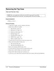
... 5. Unplug the AC adapter, if present, and remove the battery. 2. Turn the notebook top side up with the rear panel facing forward. 7. Removing the Top Case (Service Partners Only) NOTE: This section applies only to HP Pavilion 4x00, HP Compaq nx9005 and nx9000, Compaq Evo Notebook N1050v and N1010v, and Compaq Presario 2100 and 1100 models. Required Equipment 1 Phillips screwdriver...
... 5. Unplug the AC adapter, if present, and remove the battery. 2. Turn the notebook top side up with the rear panel facing forward. 7. Removing the Top Case (Service Partners Only) NOTE: This section applies only to HP Pavilion 4x00, HP Compaq nx9005 and nx9000, Compaq Evo Notebook N1050v and N1010v, and Compaq Presario 2100 and 1100 models. Required Equipment 1 Phillips screwdriver...

Maintenance and Service Guide
Page 56
...page 2-20) • Display assembly (page 2-23) 3. Unplug the AC adapter, if present, and then remove the battery. 2. Remove the following 16 screws: • Six M2.5×7.0mm screws on the rear edge of the notebook • Two M2.5×6.0mm screws on each side of the docking connector • One M2.5×... screws around the middle fan vent • One M2.5×4.0mm screw in the battery bay • Three M2.5×7.0mm screws on the front edge of each screw as it is removed and install it in damage to HP Pavilion 5x00, HP Compaq nx9010 and HP nx9008, and Compaq Presario 2500 models.
...page 2-20) • Display assembly (page 2-23) 3. Unplug the AC adapter, if present, and then remove the battery. 2. Remove the following 16 screws: • Six M2.5×7.0mm screws on the rear edge of the notebook • Two M2.5×6.0mm screws on each side of the docking connector • One M2.5×... screws around the middle fan vent • One M2.5×4.0mm screw in the battery bay • Three M2.5×7.0mm screws on the front edge of each screw as it is removed and install it in damage to HP Pavilion 5x00, HP Compaq nx9010 and HP nx9008, and Compaq Presario 2500 models.
Maintenance and Service Guide
Page 59
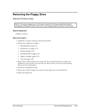
...3. Disconnect the motherboard cable. 5. These screws were removed during the top case removal procedure.) 4. Service Manual Removal and Replacement 2-29 Unplug the AC adapter, if present, and remove the battery. 2. Remove the two M2.5×4.0mm screws that secure the ...Remove the two M2.5×4.0mm screws (right side) that the screws (left side) are missing. Remove the floppy drive. Removing the Floppy Drive (Service Partners Only) NOTE: This section applies only to HP Pavilion ze4x00, HP Compaq nx9005 and nx9000, Compaq Evo Notebook N1050v and N1010v, and Compaq Presario 2100...
...3. Disconnect the motherboard cable. 5. These screws were removed during the top case removal procedure.) 4. Service Manual Removal and Replacement 2-29 Unplug the AC adapter, if present, and remove the battery. 2. Remove the two M2.5×4.0mm screws that secure the ...Remove the two M2.5×4.0mm screws (right side) that the screws (left side) are missing. Remove the floppy drive. Removing the Floppy Drive (Service Partners Only) NOTE: This section applies only to HP Pavilion ze4x00, HP Compaq nx9005 and nx9000, Compaq Evo Notebook N1050v and N1010v, and Compaq Presario 2100...

Maintenance and Service Guide
Page 61
... the TouchPad bracket on the top case. 4. Remove the M2.0×3.0mm screw that secures the floppy drive bezel to HP Pavilion 5x00, HP Compaq nx9010 and nx9008, and Compaq Presario 2500 models. Unplug the AC adapter, if present, and then remove the battery. 2. Required Equipment • 1 Phillips screwdriver Removal Procedure 1. NOTE: This section applies only to...
... the TouchPad bracket on the top case. 4. Remove the M2.0×3.0mm screw that secures the floppy drive bezel to HP Pavilion 5x00, HP Compaq nx9010 and nx9008, and Compaq Presario 2500 models. Unplug the AC adapter, if present, and then remove the battery. 2. Required Equipment • 1 Phillips screwdriver Removal Procedure 1. NOTE: This section applies only to...

Maintenance and Service Guide
Page 63
Unplug the AC adapter, if present, and then remove the battery. 2. Removing the Infrared (I/R) PCA (Service Partners Only) Required Equipment 1 Phillips screwdriver Removal Procedure 1. Remove these additional assemblies: • Hard disk drive (page 2-9) • Keyboard cover (page 2-13) • Keyboard (page 2-16) • Switchboard PCA (page 2-19) • Display assembly (page 2-23) • Top case (page 2-26) Service Manual Removal and Replacement 2-33
Unplug the AC adapter, if present, and then remove the battery. 2. Removing the Infrared (I/R) PCA (Service Partners Only) Required Equipment 1 Phillips screwdriver Removal Procedure 1. Remove these additional assemblies: • Hard disk drive (page 2-9) • Keyboard cover (page 2-13) • Keyboard (page 2-16) • Switchboard PCA (page 2-19) • Display assembly (page 2-23) • Top case (page 2-26) Service Manual Removal and Replacement 2-33


