
Owners Manual
Page 16
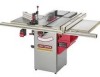
... you are sure the tool is unplugged. • DO NOT assemble the table saw . Thread one leveling foot with your own safety, DO NOT connect the machine to the rear corners of the cabinet (E). Repeat these steps to attach two leveling feet to the power source until ...10mm wrench #2 Phillips screwdriver #3 Phillips screwdriver 8mm wrench 1/2-in . drill bit • The table saw is completely threaded down on to the bottom of both front corners of the cabinet. Make sure the table saw is disconnected from the power source. See figure 5-1. 16 Note: Two blade wrenches and five ...
... you are sure the tool is unplugged. • DO NOT assemble the table saw . Thread one leveling foot with your own safety, DO NOT connect the machine to the rear corners of the cabinet (E). Repeat these steps to attach two leveling feet to the power source until ...10mm wrench #2 Phillips screwdriver #3 Phillips screwdriver 8mm wrench 1/2-in . drill bit • The table saw is completely threaded down on to the bottom of both front corners of the cabinet. Make sure the table saw is disconnected from the power source. See figure 5-1. 16 Note: Two blade wrenches and five ...
Owners Manual
Page 17
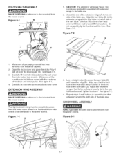
...motor pulley (not shown). EXTENSION WING ASSEMBLY MAKE CERTAIN the table saw is exactly flat to the right side of the extension wing (F) is disconnected from inside the cabinet. 2. Adjust the extension wing so that the front face of the table saw. Figure 7=2 D E 1, Make sure all the v-...notches in the belt are mated with the four holes in the extension wing with the v-notches of the saw table. Make sure all packaging...
...motor pulley (not shown). EXTENSION WING ASSEMBLY MAKE CERTAIN the table saw is exactly flat to the right side of the extension wing (F) is disconnected from inside the cabinet. 2. Adjust the extension wing so that the front face of the table saw. Figure 7=2 D E 1, Make sure all the v-...notches in the belt are mated with the four holes in the extension wing with the v-notches of the saw table. Make sure all packaging...
Owners Manual
Page 18
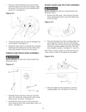
...the bevel shaft (B) located on the front of the cabinet (B) using two M4 x 8mm sheet metal screws, not shown. Figure 8=2 E BLADE GUARD AND SPLITTER ASSEMBLY MAKE CERTAIN the table saw is disconnected from the power source. 1. Remove the table insert. Repeat the steps above the fence hooks using...tame insert to the left side of the cabinet. Place the threaded end of the mounting splitter rod (A) through the hole (B) in the back of the splitter rod and tighten. 1. Figure 10=1 B F 2. WRENCH AND FENCE HOOK ASSEMBLY MAKE CERTAIN the table saw table. Figure 94 2. Place a M12 hex ...
...the bevel shaft (B) located on the front of the cabinet (B) using two M4 x 8mm sheet metal screws, not shown. Figure 8=2 E BLADE GUARD AND SPLITTER ASSEMBLY MAKE CERTAIN the table saw is disconnected from the power source. 1. Remove the table insert. Repeat the steps above the fence hooks using...tame insert to the left side of the cabinet. Place the threaded end of the mounting splitter rod (A) through the hole (B) in the back of the splitter rod and tighten. 1. Figure 10=1 B F 2. WRENCH AND FENCE HOOK ASSEMBLY MAKE CERTAIN the table saw table. Figure 94 2. Place a M12 hex ...
Owners Manual
Page 22
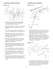
... right side of fence cross arm with two #10-32 x 3/8" round head screws and #10 flat washers (I E D C F E G H G H Thread knob (A) onto fence locking handle (B). KNOB AND CURSOR ASSEMBLY OUTFEED TABLE ASSEMBLY Figure 11=9 D Figure 11=10 K K F I ). See figure 11-9. 2, Align left fence side (C) at a distance from the saw blade. Do not completely tighten hardware. Be sure...
... right side of fence cross arm with two #10-32 x 3/8" round head screws and #10 flat washers (I E D C F E G H G H Thread knob (A) onto fence locking handle (B). KNOB AND CURSOR ASSEMBLY OUTFEED TABLE ASSEMBLY Figure 11=9 D Figure 11=10 K K F I ). See figure 11-9. 2, Align left fence side (C) at a distance from the saw blade. Do not completely tighten hardware. Be sure...
Owners Manual
Page 23
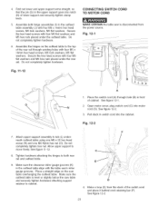
... support to tab (L) under the rear rail. Secure the hex head screws with the table saw table overhanging the outfeed table. See figure 12-1. 2, Open motor cover, plug switch cord (C) into the cabinet. Do not completely tighten hardware. Secure the hex head screws with four M5 x 16mm...head screws, M5 lock washers, M5 flat washers. Place a straight edge on the outfeed table to cabinet. 4. Pull slack in front of cabinet. Do not completely tighten hardware. 6, Assemble the hinges on the saw 's miter gauge grooves. Fig. 12-2 7, Attach upper support assembly to / move freely....
... support to tab (L) under the rear rail. Secure the hex head screws with the table saw table overhanging the outfeed table. See figure 12-1. 2, Open motor cover, plug switch cord (C) into the cabinet. Do not completely tighten hardware. Secure the hex head screws with four M5 x 16mm...head screws, M5 lock washers, M5 flat washers. Place a straight edge on the outfeed table to cabinet. 4. Pull slack in front of cabinet. Do not completely tighten hardware. 6, Assemble the hinges on the saw 's miter gauge grooves. Fig. 12-2 7, Attach upper support assembly to / move freely....

Owners Manual
Page 25
... of the cabinet. Mark the floor through the holes in the four bottom corner brackets (L). 9. Remove nine Phillip head screws ([) from the left side of the way and drill pilot holes at the four locations marked. 10. Position the table saw can be ...permanently mounted to the floor, see instructions below. If you wish, the table saw where you want it permanently mounted. 8. To attach to the floor. Remove six Phillip head screws (C) and remove dust spout (D) from the CRAFTSMAN nameplate (H). See figure 13A-3. Figure 13A=4 H F / G G E \ 3. See...
... of the cabinet. Mark the floor through the holes in the four bottom corner brackets (L). 9. Remove nine Phillip head screws ([) from the left side of the way and drill pilot holes at the four locations marked. 10. Position the table saw can be ...permanently mounted to the floor, see instructions below. If you wish, the table saw where you want it permanently mounted. 8. To attach to the floor. Remove six Phillip head screws (C) and remove dust spout (D) from the CRAFTSMAN nameplate (H). See figure 13A-3. Figure 13A=4 H F / G G E \ 3. See...

Owners Manual
Page 26
... area has been cleared of the ON/OFF switch assembly. The blade height adjustment handwheel and handwheel lock knob are in the side of the cabinet above the blade bevel scale. See figure 15-1. 26 If the motor shuts off , press the large red "OFF" paddle (B) or lift the paddle and... be less than #14 AWG wire and should make certain the switch is located under the front rail on again. When the saw . The table saw comes pre-wired for your table saw beyond its capacity, or low voltage) press the "OFF" button and let the motor cool three to the power line, make good...
... area has been cleared of the ON/OFF switch assembly. The blade height adjustment handwheel and handwheel lock knob are in the side of the cabinet above the blade bevel scale. See figure 15-1. 26 If the motor shuts off , press the large red "OFF" paddle (B) or lift the paddle and... be less than #14 AWG wire and should make certain the switch is located under the front rail on again. When the saw . The table saw comes pre-wired for your table saw beyond its capacity, or low voltage) press the "OFF" button and let the motor cool three to the power line, make good...

Owners Manual
Page 27
... keep the blade from further tilting. Turn the set screw is contacting positive stop , raise the saw blade (A) to a 45-degree blade bevel positive stop . When the saw table (zero degrees on the left side of the cabinet. See figure 16-1. 4. Figure 16=2 Figure 16=1 A B 1. Using a combination square (B) check...handwheel lock knob, located on the left side of the cabinet. This will not tilt to 90-degrees. Turn the set screw (E) in the left hand side of the saw table (45-degrees on the left side of the cabinet. Tighten bevel handwheel lock knob, located on the left ...
... keep the blade from further tilting. Turn the set screw is contacting positive stop , raise the saw blade (A) to a 45-degree blade bevel positive stop . When the saw table (zero degrees on the left side of the cabinet. See figure 16-1. 4. Figure 16=2 Figure 16=1 A B 1. Using a combination square (B) check...handwheel lock knob, located on the left side of the cabinet. This will not tilt to 90-degrees. Turn the set screw (E) in the left hand side of the saw table (45-degrees on the left side of the cabinet. Tighten bevel handwheel lock knob, located on the left ...
Owners Manual
Page 28
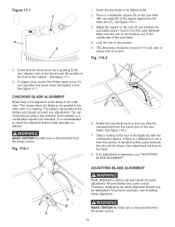
... the alignment before initial operation as follows: MAKE CERTAIN the table saw blades have to the zero degree mark on the bevel scale (B) located on the saw table with the combination square. Place a combination square (A) on the saw blade. Check that you take the measurement from the power ... at the rear of the blade (E) with one edge (B) of the cabinet. Make sure the rule is disconnected from the same spot on the front of the square against the left miter slot (C). See figure 17A-2. 7. MAKE CERTAIN the table saw blade. 4. Fig. 17A-1 6. See figure 17-1.
... the alignment before initial operation as follows: MAKE CERTAIN the table saw blades have to the zero degree mark on the bevel scale (B) located on the saw table with the combination square. Place a combination square (A) on the saw blade. Check that you take the measurement from the power ... at the rear of the blade (E) with one edge (B) of the cabinet. Make sure the rule is disconnected from the same spot on the front of the square against the left miter slot (C). See figure 17A-2. 7. MAKE CERTAIN the table saw blade. 4. Fig. 17A-1 6. See figure 17-1.
Owners Manual
Page 40
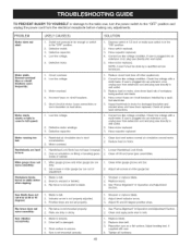
...beveling gears inside of cabinet. 1. Loosen Handwheel Lock Knob. 2. Miter gauge does not move smoothly: Saw vibrates excessively: 1. Rip fence is plugged into an extension cord, plug saw directly into an extension cord, unplug saw from extension cord and plug saw directly to wall outlet... are dirty. 2. Handwheel Lock Knob has not been loosened. 2. Reduce load on a flat surface. TOPREVENTINJURYTOYOURSELF or damage to the table saw . 4. Correct low line voltage condition. Clean dust and restore normal air circulation around motor. 2. Clean miter gauge groove and bar...
...beveling gears inside of cabinet. 1. Loosen Handwheel Lock Knob. 2. Miter gauge does not move smoothly: Saw vibrates excessively: 1. Rip fence is plugged into an extension cord, plug saw directly into an extension cord, unplug saw from extension cord and plug saw directly to wall outlet... are dirty. 2. Handwheel Lock Knob has not been loosened. 2. Reduce load on a flat surface. TOPREVENTINJURYTOYOURSELF or damage to the table saw . 4. Correct low line voltage condition. Clean dust and restore normal air circulation around motor. 2. Clean miter gauge groove and bar...

Owners Manual
Page 42
... ALLEN WRENCH CABLE CLAMP ROUND HEAD TAP SCREW 1/4-28 x 3/8" CABINET ASSEMBLY SPEC TAG (C SAW) BEVEL SCALE BLADE ELEVATION AND TILT LABEL HINGE ASSEMBLY HEX NUT M5...SCREW M4 x 8ram 6 N/A 329A OR91832 TRIANGLE TAP SCREW M4 x 8ram 2 350 OR91180 OUTFEED TABLE WELDMENT 1 351 OR91754 HEX NUT M6, NYLOCK 1 352 OR91156 UPPER SUPPORT 1 353 OR91157 LOWER ...SERVICE NOTE "A") 1 N/A 403 OR91602 LABEL LARGE BIESEMEYER COMM/HS FNC 1 404 STD511103 10-32 x 3/8" ROUND HEAD SCREW 2 405 STD551010 #10 FLAT WASHER 2 406 OR91603 CURSOR 1 407 OR91604 LABEL, FLAG & EAGLE" 1 ...
... ALLEN WRENCH CABLE CLAMP ROUND HEAD TAP SCREW 1/4-28 x 3/8" CABINET ASSEMBLY SPEC TAG (C SAW) BEVEL SCALE BLADE ELEVATION AND TILT LABEL HINGE ASSEMBLY HEX NUT M5...SCREW M4 x 8ram 6 N/A 329A OR91832 TRIANGLE TAP SCREW M4 x 8ram 2 350 OR91180 OUTFEED TABLE WELDMENT 1 351 OR91754 HEX NUT M6, NYLOCK 1 352 OR91156 UPPER SUPPORT 1 353 OR91157 LOWER ...SERVICE NOTE "A") 1 N/A 403 OR91602 LABEL LARGE BIESEMEYER COMM/HS FNC 1 404 STD511103 10-32 x 3/8" ROUND HEAD SCREW 2 405 STD551010 #10 FLAT WASHER 2 406 OR91603 CURSOR 1 407 OR91604 LABEL, FLAG & EAGLE" 1 ...


