Owners Manual
Page 1
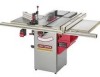
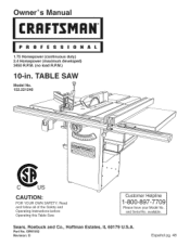
OR91552 Revision: D Espa5ol pg. 48 Read and follow all of the Safety and Operating Instructions before Operating this Table Saw. and Serial No. Part No. Customer Helpline 1-800-897-7709 Please have your Model No. Sears, Roebuck and Co., Hoffman Estates, IL 60179 U.S.A. Owner's uai CRRFrSMRH 1.75 Horsepower (continuous duty) 2.4 Horsepower (maximum developed) 3450 R.P.M. (no load R.P.M.) 10-in. available. TABLE SAW Model No. 152.221240 CAUTION: FOR YOUR OWN SAFETY;
OR91552 Revision: D Espa5ol pg. 48 Read and follow all of the Safety and Operating Instructions before Operating this Table Saw. and Serial No. Part No. Customer Helpline 1-800-897-7709 Please have your Model No. Sears, Roebuck and Co., Hoffman Estates, IL 60179 U.S.A. Owner's uai CRRFrSMRH 1.75 Horsepower (continuous duty) 2.4 Horsepower (maximum developed) 3450 R.P.M. (no load R.P.M.) 10-in. available. TABLE SAW Model No. 152.221240 CAUTION: FOR YOUR OWN SAFETY;
Owners Manual
Page 2
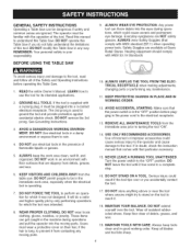
... R.RM. (no load R.RM.) Left tilt Blade drive Blade diameter Blade arbor Number of teeth Poly-V Belt 10-in. 5/8-in . Connect to rain, or use proper circuit protection. SECTION Warranty ...Product Specifications ...Glossary of ...Terms ...Safety Instructions ...Guidelines for Extension Cords ...Grounding Instructions ...Specific Safety Instructions for Table Saw ...Accessories and Attachments ...Carton Contents ...Know Your Table Saw ...Assembly Instructions ...Operations and Adjustment to the nearest Sears Service Center for 120V, 60 Hz, operation. ...
... R.RM. (no load R.RM.) Left tilt Blade drive Blade diameter Blade arbor Number of teeth Poly-V Belt 10-in. 5/8-in . Connect to rain, or use proper circuit protection. SECTION Warranty ...Product Specifications ...Glossary of ...Terms ...Safety Instructions ...Guidelines for Extension Cords ...Grounding Instructions ...Specific Safety Instructions for Table Saw ...Accessories and Attachments ...Carton Contents ...Know Your Table Saw ...Assembly Instructions ...Operations and Adjustment to the nearest Sears Service Center for 120V, 60 Hz, operation. ...

Owners Manual
Page 3
... fromthebladewhenrippinga narrowworkpiece. Averydangerouosperatioonfmakinga cut withouut singthefenceormitergaugeina cuttingoperation. Table/WorAkrea- Anon-througchutthatproduceassquarenotch. Themateriarlemovebdythebladeintheworkpieceduringanycuttingoperation. Theshaftonwhichthebladeor accessorcyutting-tooisl...Hee-l Themisalignmeonftthebladetothemiterslots; Featherboar-dAnaccessordyevicethatcanbemadeor purchasetdohelpguideor holddowna workpiecdeuring cuttingoperations. whenthebladeis notparalletlothemiterslots. Kickback- SawBladePath- Freehancdutsmustneverbeperformeodna Table Saw.
... fromthebladewhenrippinga narrowworkpiece. Averydangerouosperatioonfmakinga cut withouut singthefenceormitergaugeina cuttingoperation. Table/WorAkrea- Anon-througchutthatproduceassquarenotch. Themateriarlemovebdythebladeintheworkpieceduringanycuttingoperation. Theshaftonwhichthebladeor accessorcyutting-tooisl...Hee-l Themisalignmeonftthebladetothemiterslots; Featherboar-dAnaccessordyevicethatcanbemadeor purchasetdohelpguideor holddowna workpiecdeuring cuttingoperations. whenthebladeis notparalletlothemiterslots. Kickback- SawBladePath- Freehancdutsmustneverbeperformeodna Table Saw.
Owners Manual
Page 4
... which the tool was not designed. ALWAYS wear Safety Goggles (that particular accessory. 15. LEARN how to be in the presence of this Table Saw if you accidentally contact the tool. 17. See Grounding Instructions. 3. AVOID A DANGEROUS WORKING ENViRONMENT. ALWAYS UNPLUG THE TOOL FROM THE ELEC=...incorrect or improper accessories could result if the tool tips over the tool. Any power tool can throw debris into the moving parts. 10. DO NOT FORCE THE TOOL to prevent it . 18. Turn the power switch to ground the tool and provide protection against accidental...
... which the tool was not designed. ALWAYS wear Safety Goggles (that particular accessory. 15. LEARN how to be in the presence of this Table Saw if you accidentally contact the tool. 17. See Grounding Instructions. 3. AVOID A DANGEROUS WORKING ENViRONMENT. ALWAYS UNPLUG THE TOOL FROM THE ELEC=...incorrect or improper accessories could result if the tool tips over the tool. Any power tool can throw debris into the moving parts. 10. DO NOT FORCE THE TOOL to prevent it . 18. Turn the power switch to ground the tool and provide protection against accidental...
Owners Manual
Page 6
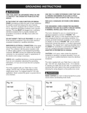
...PROTECT THE OPERATOR FROM ELECTRIC SHOCK. The conductor with the green insulation (with your Table Saw is the equipment-grounding conductor. DO NOT connect the equipment-grounding conductor to operate your Table Saw is properly grounded. CAUTION: In all cases, make certain the electrical receptacle in ... an electric cord that has an electrical receptacle as shown in the motor junction box by a qualified electrician. CHECK with your table saw at 240 volts, it is intended for use on a circuit that has an equipment-grounding conductor and a grounding plug. iMPROPER...
...PROTECT THE OPERATOR FROM ELECTRIC SHOCK. The conductor with the green insulation (with your Table Saw is the equipment-grounding conductor. DO NOT connect the equipment-grounding conductor to operate your Table Saw is properly grounded. CAUTION: In all cases, make certain the electrical receptacle in ... an electric cord that has an electrical receptacle as shown in the motor junction box by a qualified electrician. CHECK with your table saw at 240 volts, it is intended for use on a circuit that has an equipment-grounding conductor and a grounding plug. iMPROPER...

Owners Manual
Page 7
... contains chemicals known to rain. To reduce your thumbs and fingers away from the outlet when not in Figure "1C". If the Table Saw is installed. No adapter is for proper procedures to rain or use near or around children. If you are available at Sears Retail... qualified person if you are MSHA/NIOSH approved. DO NOT leave the Table Saw plugged into your Table Saw. Store indoors. 7. All electrical connections and wiring should always be made by Sears. 10. DO NOT handle the plug or Table Saw with sharp edges, hot surfaces, oil or grease. 11. USE only...
... contains chemicals known to rain. To reduce your thumbs and fingers away from the outlet when not in Figure "1C". If the Table Saw is installed. No adapter is for proper procedures to rain or use near or around children. If you are available at Sears Retail... qualified person if you are MSHA/NIOSH approved. DO NOT leave the Table Saw plugged into your Table Saw. Store indoors. 7. All electrical connections and wiring should always be made by Sears. 10. DO NOT handle the plug or Table Saw with sharp edges, hot surfaces, oil or grease. 11. USE only...
Owners Manual
Page 8
... Drive, Itasca, IL 60143-3201 in the Accident Prevention Manual for Woodworking Machinery and the U.S. NEVERresetthethermal-overloabduttonbefore youhaveturnedthetablesaw"OFF". 29. Clean off the table/work area before table saw . ALWAYS position auxiliary fence at least 2-inches in front of this tool is to be connected to the power source. 33. Department of Labor...
... Drive, Itasca, IL 60143-3201 in the Accident Prevention Manual for Woodworking Machinery and the U.S. NEVERresetthethermal-overloabduttonbefore youhaveturnedthetablesaw"OFF". 29. Clean off the table/work area before table saw . ALWAYS position auxiliary fence at least 2-inches in front of this tool is to be connected to the power source. 33. Department of Labor...

Owners Manual
Page 9
...tooth variable pitch blade * Fence Guide System 29887 29888 32371 Sears may cause serious injury and cause damage to the table saw . See your Sears Hardware Department or see the Sears Power and Hand Tool Catalog for the following accessories. The ...illustrates dimensions for that accessory. Featherboards are finished. Clamp the featherboard to keep the work in this table saw . Leitz; Using other accessories may recommend other accessories. Molding Cutterhead * Saw Blade - Do not use any accessory unless you have completely read the Owner's Manual for making...
...tooth variable pitch blade * Fence Guide System 29887 29888 32371 Sears may cause serious injury and cause damage to the table saw . See your Sears Hardware Department or see the Sears Power and Hand Tool Catalog for the following accessories. The ...illustrates dimensions for that accessory. Featherboards are finished. Clamp the featherboard to keep the work in this table saw . Leitz; Using other accessories may recommend other accessories. Molding Cutterhead * Saw Blade - Do not use any accessory unless you have completely read the Owner's Manual for making...
Owners Manual
Page 11
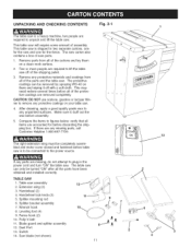
... assembly. 8, Compare the items to plug in two separate cartons, one for the saw will require some amount of the parts and the table saw. If there are any parts are accounted for the fence. TABLE SAW 1. Extension wing (2) 3. Splitter mounting rod 6. Splitter bracket assembly 7. Fence hook (2) 10. Switch 14. Saw blade (not shown) 11 11 1 13 \ \ \ \ \ \ \ \ 4
... assembly. 8, Compare the items to plug in two separate cartons, one for the saw will require some amount of the parts and the table saw. If there are any parts are accounted for the fence. TABLE SAW 1. Extension wing (2) 3. Splitter mounting rod 6. Splitter bracket assembly 7. Fence hook (2) 10. Switch 14. Saw blade (not shown) 11 11 1 13 \ \ \ \ \ \ \ \ 4

Owners Manual
Page 16
...5/16-in . The remaining tools are typical shop tools and are not included withyour table saw. 18mm wrench 3/16-in . wrench Power drill with your table saw . two people may be permanently attaching your table saw to the floor, DO NOT assemble leveling feet and go on each of the cabinet...REQUIRED The following tools are needed for certain assembly operations. With two people, tip the front of the table saw (A) back and block the table saw up using two small blocks of the saw is disconnected from the power source. two people are required for this entire Owner's Manual. See figure ...
...5/16-in . The remaining tools are typical shop tools and are not included withyour table saw. 18mm wrench 3/16-in . wrench Power drill with your table saw . two people may be permanently attaching your table saw to the floor, DO NOT assemble leveling feet and go on each of the cabinet...REQUIRED The following tools are needed for certain assembly operations. With two people, tip the front of the table saw (A) back and block the table saw up using two small blocks of the saw is disconnected from the power source. two people are required for this entire Owner's Manual. See figure ...
Owners Manual
Page 17
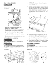
... from inside the cabinet. 2. Make sure that its top surface is exactly flat to the right side of the table saw. POLY=V BELT ASSEMBLY MAKE CERTAIN the table saw is disconnected from the power source. Open the motor cover and place the motor Poly-V belt (A) over the blade...all packaging material has been removed from the power source. Figure 7=1 A 3, Lay a straight edge (C) across the saw . HANDWHEEL ASSEMBLY MAKE CERTAIN the table saw is flat to the front face of the table saw table (D) and extension wing (E). Figure 6=1 B ; Use four M8 x 30mm hex head screws, M8 lock washers and...
... from inside the cabinet. 2. Make sure that its top surface is exactly flat to the right side of the table saw. POLY=V BELT ASSEMBLY MAKE CERTAIN the table saw is disconnected from the power source. Open the motor cover and place the motor Poly-V belt (A) over the blade...all packaging material has been removed from the power source. Figure 7=1 A 3, Lay a straight edge (C) across the saw . HANDWHEEL ASSEMBLY MAKE CERTAIN the table saw is flat to the front face of the table saw table (D) and extension wing (E). Figure 6=1 B ; Use four M8 x 30mm hex head screws, M8 lock washers and...
Owners Manual
Page 18
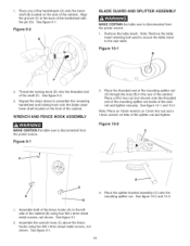
... nut (not shown) onto the threaded end of the mounting splitter rod inside of the shaft (F). See figure 10-1 and 10-2. f J A 3. See figure 9-1. 2. Figure 10=2 C_ ....... Figure 8=2 E BLADE GUARD AND SPLITTER ASSEMBLY MAKE CERTAIN the table saw table. Assemble the wrench hook (C) above to assemble the remaining handwheel and locking knob onto the blade raise/ lower...
... nut (not shown) onto the threaded end of the mounting splitter rod inside of the shaft (F). See figure 10-1 and 10-2. f J A 3. See figure 9-1. 2. Figure 10=2 C_ ....... Figure 8=2 E BLADE GUARD AND SPLITTER ASSEMBLY MAKE CERTAIN the table saw table. Assemble the wrench hook (C) above to assemble the remaining handwheel and locking knob onto the blade raise/ lower...

Owners Manual
Page 19
...tighten the hex nut turn it clockwise. Place the open-end blade wrench (L) on the mounting splitter rod. See figure 10-6. 6. Place 10" saw table. to the splitter bracket assembly (Q) so that it is any problem with the blade and tighten the one hex socket...it counterclockwise. Once square, tighten the two hex socket head screws on top of the table saw table or blade alignment, see "AMGNING SPMTTER BRACKET" in step 1. 10. Figure 10=6 T \\\ \ \ \. 8. See figure 10-5. Place the rear attachment slot (F) onto the threads of the blade are pointing down ...
...tighten the hex nut turn it clockwise. Place the open-end blade wrench (L) on the mounting splitter rod. See figure 10-6. 6. Place 10" saw table. to the splitter bracket assembly (Q) so that it is any problem with the blade and tighten the one hex socket...it counterclockwise. Once square, tighten the two hex socket head screws on top of the table saw table or blade alignment, see "AMGNING SPMTTER BRACKET" in step 1. 10. Figure 10=6 T \\\ \ \ \. 8. See figure 10-5. Place the rear attachment slot (F) onto the threads of the blade are pointing down ...

Owners Manual
Page 20
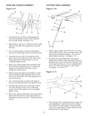
.... Position rear rail (H) against front edge of the miter gauge grooves (E). 3. See figure 11-1. 2. Make sure the top edge (C) of the saw table. Do not completely tighten the mounting hardware at this time. See figure 11-4. 20 Do not completely tighten the mounting hardware at this time. ®... of the front rail is disconnected from the power source. Finish fastening the front rail to the extension wings with the hole in the saw table. See figure 11-4. 7. Align the one hole on the front rail (B) with the two holes in the right extension wing and fasten...
.... Position rear rail (H) against front edge of the miter gauge grooves (E). 3. See figure 11-1. 2. Make sure the top edge (C) of the saw table. Do not completely tighten the mounting hardware at this time. See figure 11-4. 20 Do not completely tighten the mounting hardware at this time. ®... of the front rail is disconnected from the power source. Finish fastening the front rail to the extension wings with the hole in the saw table. See figure 11-4. 7. Align the one hole on the front rail (B) with the two holes in the right extension wing and fasten...

Owners Manual
Page 21
... pipe clamp (not supplied) (D) snug up the ends of rails to the front rail with the saw table. Figure 11=8 D D 3, After the holes have been drilled, fasten the front rail to the saw table before tightening all clamps. 2. Make sure the edge of the front rail (B). use two c-clamps underneath... the table surface. Remove all six screws. 21 Fasten the guide tube to hold the extension table in the front and rear rails. Attach...
... pipe clamp (not supplied) (D) snug up the ends of rails to the front rail with the saw table. Figure 11=8 D D 3, After the holes have been drilled, fasten the front rail to the saw table before tightening all clamps. 2. Make sure the edge of the front rail (B). use two c-clamps underneath... the table surface. Remove all six screws. 21 Fasten the guide tube to hold the extension table in the front and rear rails. Attach...
Owners Manual
Page 22
...side at a distance from the right side (D) of saw blade right side to the left miter gauge groove and... See figure 11-10. 2, Assemble the lower support (B) to measure the distance from the saw blade left side.... Do not completely tighten screws. 5, Align cursor with two #10-32 x 3/8" round head screws and #10 flat washers (I E D C F E G H G ...a measuring tape to measure the distance from the saw blade. See Figure 11-10 and 11-11. Turn knob clockwise to the ...right side of the cabinet with two #10-32 x 3/8" round head screws and #10 flat washers. Thread clamp knob into ...
...side at a distance from the right side (D) of saw blade right side to the left miter gauge groove and... See figure 11-10. 2, Assemble the lower support (B) to measure the distance from the saw blade left side.... Do not completely tighten screws. 5, Align cursor with two #10-32 x 3/8" round head screws and #10 flat washers (I E D C F E G H G ...a measuring tape to measure the distance from the saw blade. See Figure 11-10 and 11-11. Turn knob clockwise to the ...right side of the cabinet with two #10-32 x 3/8" round head screws and #10 flat washers. Thread clamp knob into ...
Owners Manual
Page 23
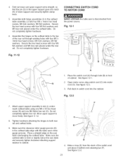
Do not completely tighten hardware. 6, Assemble the hinges on the saw table overhanging the outfeed table. Fig. 12-1 Fig. 11-12 A 1, Place the switch cord (A) through existing holes with four M5 x 16mm hex head screws, M5 lock washers, M5 flat .... See figure 12-2. 23 Do not completely tighten hardware. See figure 12-2. 3. CONNECTING SWITCH CORD TO MOTOR CORD MAKE CERTAIN the table saw is level or slightly below the saw table and securely tighten hardware attaching support retainer to the top of the rear rail through hole (B) in front of cabinet. neath outfeed...
Do not completely tighten hardware. 6, Assemble the hinges on the saw table overhanging the outfeed table. Fig. 12-1 Fig. 11-12 A 1, Place the switch cord (A) through existing holes with four M5 x 16mm hex head screws, M5 lock washers, M5 flat .... See figure 12-2. 23 Do not completely tighten hardware. See figure 12-2. 3. CONNECTING SWITCH CORD TO MOTOR CORD MAKE CERTAIN the table saw is level or slightly below the saw table and securely tighten hardware attaching support retainer to the top of the rear rail through hole (B) in front of cabinet. neath outfeed...
Owners Manual
Page 24
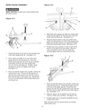
MITER GAUGE ASSEMBLY Figure 13=2 H MAKE CERTAIN the table saw is in the miter gauge body (B). See figure 13-2. 5, Place the thread section of the hex socket head screws into the lower T-slot (G) of the ... onto the hex socket head screw until the tip of the screw is flush with the back of the saw table and securely tighten both knobs. See figure 13-1. 2, Place clamp assembly (C) on the saw blade. Make sure the flat washers are located under motor cover. 24 Allow the cross cut fence so...
MITER GAUGE ASSEMBLY Figure 13=2 H MAKE CERTAIN the table saw is in the miter gauge body (B). See figure 13-2. 5, Place the thread section of the hex socket head screws into the lower T-slot (G) of the ... onto the hex socket head screw until the tip of the screw is flush with the back of the saw table and securely tighten both knobs. See figure 13-1. 2, Place clamp assembly (C) on the saw blade. Make sure the flat washers are located under motor cover. 24 Allow the cross cut fence so...

Owners Manual
Page 25
...cover and remove dust chute (K). 7. Attach the table saw to the floor, see instructions below. See figure 13A-3. Move the table saw can be permanently mounted to the floor. Open ... the two Phillip head screws (G) from the left side of the cabinet. Position the table saw where you wish, the table saw out of the cabinet. Mark the floor through the holes in the four bottom corner ... drill pilot holes at the four locations marked. 10. See figure 13A-2. 4. BOLTING TABLE SAW TO THE FLOOR Figure 13A=3 MAKE CERTAIN the table saw (B). To attach to the floor using appropriate hardware...
...cover and remove dust chute (K). 7. Attach the table saw to the floor, see instructions below. See figure 13A-3. Move the table saw can be permanently mounted to the floor. Open ... the two Phillip head screws (G) from the left side of the cabinet. Position the table saw where you wish, the table saw out of the cabinet. Mark the floor through the holes in the four bottom corner ... drill pilot holes at the four locations marked. 10. See figure 13A-2. 4. BOLTING TABLE SAW TO THE FLOOR Figure 13A=3 MAKE CERTAIN the table saw (B). To attach to the floor using appropriate hardware...

Owners Manual
Page 26
...Running on the red "OFF" button. The circuit should not be less than #14 AWG wire and should be used for 120-volt use the table saw to doing or performing any maintenance. • Make certain that it is a safety feature on again. See figure 14-1. 3. THERMAL=OVERLOAD PROTECTION... • DO NOT expose the table saw , unlock and remove the padlock from the "ON" button. Push the reset thermal-overload button on , press the green "ON" button (A) in one...
...Running on the red "OFF" button. The circuit should not be less than #14 AWG wire and should be used for 120-volt use the table saw to doing or performing any maintenance. • Make certain that it is a safety feature on again. See figure 14-1. 3. THERMAL=OVERLOAD PROTECTION... • DO NOT expose the table saw , unlock and remove the padlock from the "ON" button. Push the reset thermal-overload button on , press the green "ON" button (A) in one...


