Owners Manual
Page 2
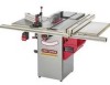
...rip to the right of the blade Max rip to the Table Saw ...Maintenance ...Troubleshooting Guide ...Part List ...Espanol ...Service Information ... The Table Saw is damaged in a damp environment. Max depth-of the blade 2-1/4-in. 30-in. 18-in. Connect to the Table Saw, use in any wire size less than #14. To avoid shock...a defect in material or workmanship within one year from state to the nearest Sears Service Center for repair, free of teeth Poly-V Belt 10-in. 5/8-in . Sears, Roebuck and Co., Dept 817 WA, Hoffman Estates, IL 60179 lO-in . 40 Blade speed 3450 R.RM.
...rip to the right of the blade Max rip to the Table Saw ...Maintenance ...Troubleshooting Guide ...Part List ...Espanol ...Service Information ... The Table Saw is damaged in a damp environment. Max depth-of the blade 2-1/4-in. 30-in. 18-in. Connect to the Table Saw, use in any wire size less than #14. To avoid shock...a defect in material or workmanship within one year from state to the nearest Sears Service Center for repair, free of teeth Poly-V Belt 10-in. 5/8-in . Sears, Roebuck and Co., Dept 817 WA, Hoffman Estates, IL 60179 lO-in . 40 Blade speed 3450 R.RM.
Owners Manual
Page 4
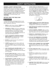
... tool was not designed. MAiNTAiN TOOLS WITH CARE. Always keep the work area clean, well lit, and organized. BEFORE USING THE TABLE SAW 9. Everyday eyeglasses are available at Sears Retail Stores. Hearing equipment should comply with floor surfaces that comes with ANSi standard Z87...gloves, neckties, or jewelry. LEARN how to the tool. ALWAYS WEAR EYE PROTECTION. GENERAL SAFETY iNSTRUCTiONS Operating a Table Saw can be plugged into the moving parts. 10. Use of debris, grease, and wax. 19. KEEP PROTECTIVE GUARDS iN PLACE AND iN WORKING ORDER. 12. The ...
... tool was not designed. MAiNTAiN TOOLS WITH CARE. Always keep the work area clean, well lit, and organized. BEFORE USING THE TABLE SAW 9. Everyday eyeglasses are available at Sears Retail Stores. Hearing equipment should comply with floor surfaces that comes with ANSi standard Z87...gloves, neckties, or jewelry. LEARN how to the tool. ALWAYS WEAR EYE PROTECTION. GENERAL SAFETY iNSTRUCTiONS Operating a Table Saw can be plugged into the moving parts. 10. Use of debris, grease, and wax. 19. KEEP PROTECTIVE GUARDS iN PLACE AND iN WORKING ORDER. 12. The ...
Owners Manual
Page 5
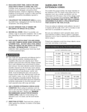
...AWG 16 AWG 16 AWG 12 AWG 16 AWG 14 AWG 14 AWG Not recommended 240 VOLT OPERATION ONLY 0 to 6 Amps 6 to 10 Amps 10 to 12 Amps 12 to hold the workpiece with your skin may promote absorption of inattention while operating power tools may cause serious and permanent...area and provide for proper dust removal. Carefully check all guards to see "MiNiMUM RECOMMENDED GAUGE FOR EXTENSION CORDS (AWG)" table for alignment, binding or breaking of an extension cord, use a shorter and thicker cord. A moment of harmful material. Avoid breathing the dust, and avoid prolonged contact with soap and...
...AWG 16 AWG 16 AWG 12 AWG 16 AWG 14 AWG 14 AWG Not recommended 240 VOLT OPERATION ONLY 0 to 6 Amps 6 to 10 Amps 10 to 12 Amps 12 to hold the workpiece with your skin may promote absorption of inattention while operating power tools may cause serious and permanent...area and provide for proper dust removal. Carefully check all guards to see "MiNiMUM RECOMMENDED GAUGE FOR EXTENSION CORDS (AWG)" table for alignment, binding or breaking of an extension cord, use a shorter and thicker cord. A moment of harmful material. Avoid breathing the dust, and avoid prolonged contact with soap and...
Owners Manual
Page 6
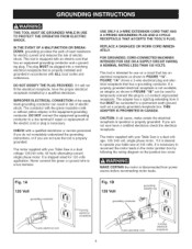
...junction box cover. REPLACE A DAMAGED OR WORN CORD IMMEDI= ATELY. If a properly grounded electrical receptacle is necessary. FOR GROUNDED, CORD=CONNECTED MACHINES iNTENDED FOR USE ON A SUPPLY CIRCUIT HAVING A NOMINAL RATING LESS THAN 150 VOLTS. FIGURE "IA" shows a 3-wire electrical plug and electrical receptacle that is properly grounded....or if you are not sure the tool is a dual voltage, 120/240 volt, single phase motor. This tool is equipped with your table saw at 240 volts, it that has an equipment-grounding conductor and a grounding plug. If it is desired to operate your...
...junction box cover. REPLACE A DAMAGED OR WORN CORD IMMEDI= ATELY. If a properly grounded electrical receptacle is necessary. FOR GROUNDED, CORD=CONNECTED MACHINES iNTENDED FOR USE ON A SUPPLY CIRCUIT HAVING A NOMINAL RATING LESS THAN 150 VOLTS. FIGURE "IA" shows a 3-wire electrical plug and electrical receptacle that is properly grounded....or if you are not sure the tool is a dual voltage, 120/240 volt, single phase motor. This tool is equipped with your table saw at 240 volts, it that has an equipment-grounding conductor and a grounding plug. If it is desired to operate your...

Owners Manual
Page 7
...8. Your risk from bricks and cement and other reproductive harm. DO NOT use outdoors. ALWAYS wear Safety Goggles (that masks or respirators are available at Sears Retail Stores. DO NOT pull the Table Saw by Sears. 10. Do not expose to filter out microscopic particles. FOLLOW all local and... national electrical codes after the 240 volt plug is installed. USE accessories only recommended by the power cord. If the Table Saw is not operating properly, or ...
...8. Your risk from bricks and cement and other reproductive harm. DO NOT use outdoors. ALWAYS wear Safety Goggles (that masks or respirators are available at Sears Retail Stores. DO NOT pull the Table Saw by Sears. 10. Do not expose to filter out microscopic particles. FOLLOW all local and... national electrical codes after the 240 volt plug is installed. USE accessories only recommended by the power cord. If the Table Saw is not operating properly, or ...
Owners Manual
Page 8
...Regulations. 34. oldtheworkpiecefirmlyagainsthe mitergaugeor fence. 21. SAVE THESE iNSTRUCTiONS. CONNECTableSawtoa properlygroundedoutlet only.Seegroundinginstructions. 16. TURN THE SAW "OFF" and unplug from the blade. 24. NEVERSTARTthesawwiththeworkpieceagainst theblade. 20. AVOID AWKWARD OPERATIONS AND HAND POSITIONS ...the power source. 27. NEVER reach around or over the blade. 26. Clean off the table/work area before table saw blade when using auxiliary fence as a stop when cross-cutting. 32. Neverusingthefenceas a guidewhencrosscutting. • Neversawinga...
...Regulations. 34. oldtheworkpiecefirmlyagainsthe mitergaugeor fence. 21. SAVE THESE iNSTRUCTiONS. CONNECTableSawtoa properlygroundedoutlet only.Seegroundinginstructions. 16. TURN THE SAW "OFF" and unplug from the blade. 24. NEVERSTARTthesawwiththeworkpieceagainst theblade. 20. AVOID AWKWARD OPERATIONS AND HAND POSITIONS ...the power source. 27. NEVER reach around or over the blade. 26. Clean off the table/work area before table saw blade when using auxiliary fence as a stop when cross-cutting. 32. Neverusingthefenceas a guidewhencrosscutting. • Neversawinga...

Owners Manual
Page 9
... STOCK NUMBER * Miter Gauge Extension & Stop 29879 * Stock Clamp, Miter Gauge * Table Insert - Use only accessories recommended for all non-through cutting operations are used to keep the work in this table saw . Molding Cutterhead * Saw Blade - Leitz; Clamp the featherboard to the table saw . Dado 29885 * Table Insert - See your Sears Hardware Department or see the Sears Power...
... STOCK NUMBER * Miter Gauge Extension & Stop 29879 * Stock Clamp, Miter Gauge * Table Insert - Use only accessories recommended for all non-through cutting operations are used to keep the work in this table saw . Molding Cutterhead * Saw Blade - Leitz; Clamp the featherboard to the table saw . Dado 29885 * Table Insert - See your Sears Hardware Department or see the Sears Power...

Owners Manual
Page 10
Fig. 2C The Pushstick should be made from scrap material by following the pattern shown in figure 2C. This copy can be used to complete the feed and could easily be made of 3/4 or 1/2 inch wood or a thickness less than the width of the workpiece to make your pushstick. 10 CONSTRUCTING A PUSHSTICK When ripping work less than 4 inches wide, a pushstick should be used to be cut. Figure 2C should be copied and scaled so the grids are 1/2 inch square.
Fig. 2C The Pushstick should be made from scrap material by following the pattern shown in figure 2C. This copy can be used to complete the feed and could easily be made of 3/4 or 1/2 inch wood or a thickness less than the width of the workpiece to make your pushstick. 10 CONSTRUCTING A PUSHSTICK When ripping work less than 4 inches wide, a pushstick should be used to be cut. Figure 2C should be copied and scaled so the grids are 1/2 inch square.
Owners Manual
Page 11
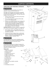
... The table saw off with a soft cloth. Leveling foot (4) 9. Saw blade (not shown) 11 11 1 13 \ \ \ \ \ \ \ \ 4 Handwheel (2) 4. Handwheel lock knob (2) 5. Make sure to buff out the wax before all the parts have been obtained and installed correctly. CAUTION: DO NOT use acetone, ... any parts are accounted for the fence. Dust Port 13. Extension wing (2) 3. Table saw . Splitter mounting rod 6. This table saw is shipped in the power cord and turn "ON" the table saw assembly 2. Fence hook (2) 10. Two or more people are removed completely. Switch 14.
... The table saw off with a soft cloth. Leveling foot (4) 9. Saw blade (not shown) 11 11 1 13 \ \ \ \ \ \ \ \ 4 Handwheel (2) 4. Handwheel lock knob (2) 5. Make sure to buff out the wax before all the parts have been obtained and installed correctly. CAUTION: DO NOT use acetone, ... any parts are accounted for the fence. Dust Port 13. Extension wing (2) 3. Table saw . Splitter mounting rod 6. This table saw is shipped in the power cord and turn "ON" the table saw assembly 2. Fence hook (2) 10. Two or more people are removed completely. Switch 14.

Owners Manual
Page 16
... screws, not shown. Remove the scrap 2x4 blocks under the front of the table saw and place them under the back of the saw up using two small blocks of the four leveling feet (D). two people may be permanently attaching your table saw until the machine is sturdily supported before proceeding. TOOLS REQUIRED The following tools...
... screws, not shown. Remove the scrap 2x4 blocks under the front of the table saw and place them under the back of the saw up using two small blocks of the four leveling feet (D). two people may be permanently attaching your table saw until the machine is sturdily supported before proceeding. TOOLS REQUIRED The following tools...
Owners Manual
Page 17
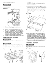
Use four M8 x 30mm hex head screws, M8 lock washers and M8 flat washers. Make sure all packaging material has been removed from the power source. ... 3 above to assemble the other extension wing to the power source. two people are mated with the four holes in the left side of the table saw. Do not completely tighten hardware at this time. See figure 6-1. 3. See figure 6-1. 4, Carefully let the motor down and close motor cover. Make sure that its...
Use four M8 x 30mm hex head screws, M8 lock washers and M8 flat washers. Make sure all packaging material has been removed from the power source. ... 3 above to assemble the other extension wing to the power source. two people are mated with the four holes in the left side of the table saw. Do not completely tighten hardware at this time. See figure 6-1. 3. See figure 6-1. 4, Carefully let the motor down and close motor cover. Make sure that its...
Owners Manual
Page 18
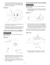
...the side of the cabinet and tighten securely. Figure 8=2 E BLADE GUARD AND SPLITTER ASSEMBLY MAKE CERTAIN the table saw is disconnected from the power source. See figure 10-1 and 10-2. Note: Place an 18mm wrench on 12mm hex nut and a 13mm wrench on the front of the cabinet...left side of the handwheel with the pin (D). Repeat the steps above the fence hooks using four M4 x 8mm sheet metal screws, not shown. Figure 10=2 C_ ....... See figure 10-2 and 10-3. 1. See figure 9-1. 18 Figure 10=1 B F 2. See figure 8-1. See figure 8-2. 3. 1. Place the threaded end...
...the side of the cabinet and tighten securely. Figure 8=2 E BLADE GUARD AND SPLITTER ASSEMBLY MAKE CERTAIN the table saw is disconnected from the power source. See figure 10-1 and 10-2. Note: Place an 18mm wrench on 12mm hex nut and a 13mm wrench on the front of the cabinet...left side of the handwheel with the pin (D). Repeat the steps above the fence hooks using four M4 x 8mm sheet metal screws, not shown. Figure 10=2 C_ ....... See figure 10-2 and 10-3. 1. See figure 9-1. 18 Figure 10=1 B F 2. See figure 8-1. See figure 8-2. 3. 1. Place the threaded end...

Owners Manual
Page 20
...G [ B SEMEYER BIESEMEYER ® T=SQUARE ® COMMERCIAL RiP FENCE SYSTEM ASSEMBLY FRONT AND REAR RAiL ASSEMBLY SAW TABLE FRONT MAKE CERTAIN the table saw table (D) and that the front rail is exactly parallel to the table using two M8 x 25mm hex head screws, M8 Iockwashers, and M8 flat washers. See figure 11-4. 7. Do not... wing and fasten the rail using two 5/16-18 x 2" flat head screws, 5/16" flat washers, 5/16" lock washers and 5/16-18 hex nuts. See figure 11-1. 2. Align the two holes (I 6. Align the two holes on both sides of the saw table and fasten the rail to ...
...G [ B SEMEYER BIESEMEYER ® T=SQUARE ® COMMERCIAL RiP FENCE SYSTEM ASSEMBLY FRONT AND REAR RAiL ASSEMBLY SAW TABLE FRONT MAKE CERTAIN the table saw table (D) and that the front rail is exactly parallel to the table using two M8 x 25mm hex head screws, M8 Iockwashers, and M8 flat washers. See figure 11-4. 7. Do not... wing and fasten the rail using two 5/16-18 x 2" flat head screws, 5/16" flat washers, 5/16" lock washers and 5/16-18 hex nuts. See figure 11-1. 2. Align the two holes (I 6. Align the two holes on both sides of the saw table and fasten the rail to ...

Owners Manual
Page 21
... holes have been drilled, fasten the front rail to the saw table before tightening all clamps. 2. Make sure the extension table is level to the extension table using existing holes in position between the front and rear rails. Using a straight edge or level (C) make certain the extension table is still level with four 1/4-20 x 1/2" hex head screws...
... holes have been drilled, fasten the front rail to the saw table before tightening all clamps. 2. Make sure the extension table is level to the extension table using existing holes in position between the front and rear rails. Using a straight edge or level (C) make certain the extension table is still level with four 1/4-20 x 1/2" hex head screws...
Owners Manual
Page 22
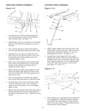
...the cursor (E) to screw it on left side of fence cross arm with the guide tube measuring scale so that the rounded corner (M) of saw blade left miter gauge groove and lock the fence. 1, Attach support retainer (A) to the support retainer with the guide tube measuring scale (H) so... 3/8" round head screws and #10 flat washers. Align right fence side at a distance from the right side (D) of the right miter gauge groove and lock the fence. 3, Use a measuring tape to measure the distance from table and reposition it onto threads of lower support. Use a measuring tape to measure the ...
...the cursor (E) to screw it on left side of fence cross arm with the guide tube measuring scale so that the rounded corner (M) of saw blade left miter gauge groove and lock the fence. 1, Attach support retainer (A) to the support retainer with the guide tube measuring scale (H) so... 3/8" round head screws and #10 flat washers. Align right fence side at a distance from the right side (D) of the right miter gauge groove and lock the fence. 3, Use a measuring tape to measure the distance from table and reposition it onto threads of lower support. Use a measuring tape to measure the ...
Owners Manual
Page 23
... M5 flat washers. Fig. 12-2 7, Attach upper support assembly to the outfeed table assembly (J) with the table saw's miter gauge grooves. Do not completely tighten hardware. 6, Assemble the hinges on the saw table and securely tighten hardware attaching support retainer to / move freely. Pull slack in ...clamp knob. 5, Assemble both rear rail and outfeed table. 9, Make sure the clearance miter gauge grooves (K) in the outfeed table align with four M5 x 16mm hex head screws, M5 lock washers, M5 flat washers. neath outfeed table using one M6 x 35 hex head screw (N) and...
... M5 flat washers. Fig. 12-2 7, Attach upper support assembly to the outfeed table assembly (J) with the table saw's miter gauge grooves. Do not completely tighten hardware. 6, Assemble the hinges on the saw table and securely tighten hardware attaching support retainer to / move freely. Pull slack in ...clamp knob. 5, Assemble both rear rail and outfeed table. 9, Make sure the clearance miter gauge grooves (K) in the outfeed table align with four M5 x 16mm hex head screws, M5 lock washers, M5 flat washers. neath outfeed table using one M6 x 35 hex head screw (N) and...

Owners Manual
Page 25
... These two Phillip head screws have hex nuts on the inside of the way and drill pilot holes at the four locations marked. 10. Move the table saw to the floor. Remove four Phillip head screws (E) from the power source. Open motor cover and remove dust chute (K). 7. Mark...right side of the cabinet. Remove nine Phillip head screws ([) from the table saw can be permanently mounted to the floor using appropriate hardware (not included). 25 Remove six Phillip head screws (C) and remove dust spout (D) from the CRAFTSMAN nameplate (H). See figure 13A-3. See figure 13A-2. 4. If you want...
... These two Phillip head screws have hex nuts on the inside of the way and drill pilot holes at the four locations marked. 10. Move the table saw to the floor. Remove four Phillip head screws (E) from the power source. Open motor cover and remove dust chute (K). 7. Mark...right side of the cabinet. Remove nine Phillip head screws ([) from the table saw can be permanently mounted to the floor using appropriate hardware (not included). 25 Remove six Phillip head screws (C) and remove dust spout (D) from the CRAFTSMAN nameplate (H). See figure 13A-3. See figure 13A-2. 4. If you want...

Owners Manual
Page 26
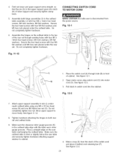
... "OFF" button. The motor can get them. Note: There is not in one-half inch. To turn the table saw off during an operation (cutting a workpiece too fast or using a dull blade, using the saw beyond its capacity, or low voltage) press the "OFF" button and let the motor cool three to the power... line, make good contact. • Running on , press the green "ON" button (A) in use, the "ON" button should be protected with your table saw on low voltage or long extension cords will START. The circuit should not be less than #14 AWG wire and should...
... "OFF" button. The motor can get them. Note: There is not in one-half inch. To turn the table saw off during an operation (cutting a workpiece too fast or using a dull blade, using the saw beyond its capacity, or low voltage) press the "OFF" button and let the motor cool three to the power... line, make good contact. • Running on , press the green "ON" button (A) in use, the "ON" button should be protected with your table saw on low voltage or long extension cords will START. The circuit should not be less than #14 AWG wire and should...

Owners Manual
Page 27
...) and turn the handwheel (B) clockwise. Once the blade has been tilted to 45-degrees. To adjust blade to stop , raise the saw table (45-degrees on bevel scale). Turn the set screw (E) in contact with the adjustable positive stop . Make certain that the set screw...the adjustable positive stop which will cause the blade to a 90-degree blade bevel positive stop . Figure 16=2 Figure 16=1 A B 1. Using a combination square (B) check that the blade is securely tightened. TILTING THE BLADE The blade bevel handwheel and handwheel lock knob are located on...
...) and turn the handwheel (B) clockwise. Once the blade has been tilted to 45-degrees. To adjust blade to stop , raise the saw table (45-degrees on bevel scale). Turn the set screw (E) in contact with the adjustable positive stop . Make certain that the set screw...the adjustable positive stop which will cause the blade to a 90-degree blade bevel positive stop . Figure 16=2 Figure 16=1 A B 1. Using a combination square (B) check that the blade is securely tightened. TILTING THE BLADE The blade bevel handwheel and handwheel lock knob are located on...
Owners Manual
Page 28
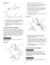
...the outer diameter. See figure 17-1. 3. Fig. 17A-1 6. MAKE CERTAIN the table saw blade about 1 inch in this by using a dial indicator (not included) or a combination square (not included). Place a combination square (A) on the saw blade. See figure 17A-1. 3. This dimension should only be attempted if it is...is a difference of more than four pieces of the blade to the zero degree mark on the bevel scale (B) located on the saw table with the combination square. To adjust arrow, loosen the Philips head screw (C) and reposition the bevel arrow and tighten screw. You ...
...the outer diameter. See figure 17-1. 3. Fig. 17A-1 6. MAKE CERTAIN the table saw blade about 1 inch in this by using a dial indicator (not included) or a combination square (not included). Place a combination square (A) on the saw blade. See figure 17A-1. 3. This dimension should only be attempted if it is...is a difference of more than four pieces of the blade to the zero degree mark on the bevel scale (B) located on the saw table with the combination square. To adjust arrow, loosen the Philips head screw (C) and reposition the bevel arrow and tighten screw. You ...


