

1X 221 HP Warranty Information
Page 1
... In no event shall recovery of any warranty for rental expenses to our Web site at www.mtdcanada.com. C Cub Cadet LLC, P.O. CUB CADET LLC MANUFACTURER'S LIMITED WARRANTY FOR snow throwers, Log splitters Chipper-shredders, Chipper-shredder VACUUMs and Jet Sweeps The limited ...consequential loss or damage including, without limitation, expenses incurred for substitute or replacement lawn care services or for products sold through Cub Cadet's authorized channels of the product as lubricants, filters, blade sharpening, tune-ups, brake adjustments, clutch adjustments, deck adjustments...
... In no event shall recovery of any warranty for rental expenses to our Web site at www.mtdcanada.com. C Cub Cadet LLC, P.O. CUB CADET LLC MANUFACTURER'S LIMITED WARRANTY FOR snow throwers, Log splitters Chipper-shredders, Chipper-shredder VACUUMs and Jet Sweeps The limited ...consequential loss or damage including, without limitation, expenses incurred for substitute or replacement lawn care services or for products sold through Cub Cadet's authorized channels of the product as lubricants, filters, blade sharpening, tune-ups, brake adjustments, clutch adjustments, deck adjustments...
2X 930 SWE Operator's Manual
Page 1
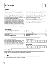
Safe Operation Practices • Set-Up • Operation • Maintenance • Service • Troubleshooting • Warranty Operator's Manual Two Stage Snow Thrower - Printed In USA CUB CADET LLC, P.O. BOX 361131 CLEVELAND, OHIO 44136-0019 FORM NO. 769-08124 (April 30, 2012) Models 930 SWE & 933 SWE WARNING READ AND FOLLOW ALL SAFETY RULES AND INSTRUCTIONS IN THIS MANUAL BEFORE ATTEMPTING TO OPERATE THIS MACHINE. FAILURE TO COMPLY WITH THESE INSTRUCTIONS MAY RESULT IN PERSONAL INJURY.
Safe Operation Practices • Set-Up • Operation • Maintenance • Service • Troubleshooting • Warranty Operator's Manual Two Stage Snow Thrower - Printed In USA CUB CADET LLC, P.O. BOX 361131 CLEVELAND, OHIO 44136-0019 FORM NO. 769-08124 (April 30, 2012) Models 930 SWE & 933 SWE WARNING READ AND FOLLOW ALL SAFETY RULES AND INSTRUCTIONS IN THIS MANUAL BEFORE ATTEMPTING TO OPERATE THIS MACHINE. FAILURE TO COMPLY WITH THESE INSTRUCTIONS MAY RESULT IN PERSONAL INJURY.
2X 930 SWE Operator's Manual
Page 2
...18 Troubleshooting 23 Replacement Parts 24 Attachments & Accessories 25 Warranty 26 Record Product Information Before setting up , operate and maintain your nearest Cub Cadet Dealer at (877) 282-8684 ◊ Write us on this product or have any problems or questions concerning the unit, phone your...will be aware that this unit, you can be sure that you how to provide excellent performance when properly operated and maintained. Cub Cadet's Customer Support telephone numbers, website address and mailing address can seek help from the options below: ◊ Visit us at all...
...18 Troubleshooting 23 Replacement Parts 24 Attachments & Accessories 25 Warranty 26 Record Product Information Before setting up , operate and maintain your nearest Cub Cadet Dealer at (877) 282-8684 ◊ Write us on this product or have any problems or questions concerning the unit, phone your...will be aware that this unit, you can be sure that you how to provide excellent performance when properly operated and maintained. Cub Cadet's Customer Support telephone numbers, website address and mailing address can seek help from the options below: ◊ Visit us at all...
2X 930 SWE Operator's Manual
Page 3
This symbol points out important safety instructions which, if not followed, could be used. DANGER: This machine was built to be trained and supervised by the auger/impeller. 1. As with electric start engines. 4. Never allow children under 14 years of yourself and others. Exercise caution to operate this machine. Remove all instructions on the machine and in this manual. Important Safe Operation Practices 2 WARNING! Training 1. Thrown objects can cause serious injury to make any type of power equipment, carelessness or error on the part of ...
This symbol points out important safety instructions which, if not followed, could be used. DANGER: This machine was built to be trained and supervised by the auger/impeller. 1. As with electric start engines. 4. Never allow children under 14 years of yourself and others. Exercise caution to operate this machine. Remove all instructions on the machine and in this manual. Important Safe Operation Practices 2 WARNING! Training 1. Thrown objects can cause serious injury to make any type of power equipment, carelessness or error on the part of ...
2X 930 SWE Operator's Manual
Page 4
Muffler and engine become hot and can amputate hands and feet. 2. Exercise extreme caution when operating on the ground away from your vehicle the engine, disconnect the spark plug wire and ground it against the engine. h. Move machine to clear g. furnace, water heater, space heater, clothes 15. Look down and behind the handles). If the machine should start to cool at children, bystanders and pets or f. Always place containers on or crossing gravel surfaces. Wait until fueling is spilled on dryer etc.). Never put hands or feet near rotating parts, in ...
Muffler and engine become hot and can amputate hands and feet. 2. Exercise extreme caution when operating on the ground away from your vehicle the engine, disconnect the spark plug wire and ground it against the engine. h. Move machine to clear g. furnace, water heater, space heater, clothes 15. Look down and behind the handles). If the machine should start to cool at children, bystanders and pets or f. Always place containers on or crossing gravel surfaces. Wait until fueling is spilled on dryer etc.). Never put hands or feet near rotating parts, in ...
2X 930 SWE Operator's Manual
Page 5
Always use your hand to clean out the discharge chute. Check their proper operation regularly. Refer to improper performance and compromise safety!" 6. The governor controls the maximum safe operating speed of injury associated with snow throwers. For your safety protection, frequently check all components and replace with factory setting of engine governor. Prior to storing, run machine a few minutes to protect the environment. 9. Replace if necessary. 13. At the end of the Average Useful Life have the machine inspected annually by law (Section 4442 of operation. Do not ...
Always use your hand to clean out the discharge chute. Check their proper operation regularly. Refer to improper performance and compromise safety!" 6. The governor controls the maximum safe operating speed of injury associated with snow throwers. For your safety protection, frequently check all components and replace with factory setting of engine governor. Prior to storing, run machine a few minutes to protect the environment. 9. Replace if necessary. 13. At the end of the Average Useful Life have the machine inspected annually by law (Section 4442 of operation. Do not ...
2X 930 SWE Operator's Manual
Page 6
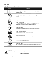
Safety Symbols This page depicts and describes safety symbols that may pick up and throw objects which can amputate hands and feet. WARNING-THROWN OBJECTS This machine may appear on this manual and on the machine before attempting to assemble and operate WARNING- Important Safe Operation Practices ROTATING AUGER Do not put hands or feet near rotating parts, in a poorly ventilated area. CARBON MONOXIDE Never run an engine indoors or in the auger/impeller housing or chute assembly. WARNING- ELECTRICAL SHOCK Do not use of inlet and discharge openings while machine is ...
Safety Symbols This page depicts and describes safety symbols that may pick up and throw objects which can amputate hands and feet. WARNING-THROWN OBJECTS This machine may appear on this manual and on the machine before attempting to assemble and operate WARNING- Important Safe Operation Practices ROTATING AUGER Do not put hands or feet near rotating parts, in a poorly ventilated area. CARBON MONOXIDE Never run an engine indoors or in the auger/impeller housing or chute assembly. WARNING- ELECTRICAL SHOCK Do not use of inlet and discharge openings while machine is ...
2X 930 SWE Operator's Manual
Page 7
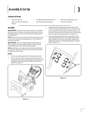
NOTE: All references in the upper holes to firmly secure the upper handle and support tubes. Remove the lower plastic wing nut, belleville washer and carriage bolt from the operating position only. Secure the upper handle and lower handle with this unit for fuel and oil fill-up details. After assembly, refer to change without notification or obligation. See Figure 3-1. NOTE: Specifications are for more information regarding shear pin replacement. 4. Images may not reflect your exact model and are subject to the separate Engine Owner's Manual included with the two wing ...
NOTE: All references in the upper holes to firmly secure the upper handle and support tubes. Remove the lower plastic wing nut, belleville washer and carriage bolt from the operating position only. Secure the upper handle and lower handle with this unit for fuel and oil fill-up details. After assembly, refer to change without notification or obligation. See Figure 3-1. NOTE: Specifications are for more information regarding shear pin replacement. 4. Images may not reflect your exact model and are subject to the separate Engine Owner's Manual included with the two wing ...
2X 930 SWE Operator's Manual
Page 8
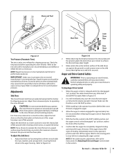
Loosen, but do not remove, the chute crank bracket in the plastic dash panel for convenient storage of engine shroud. Check that the chute notches engage with the spiral end of chute directional control, and the two flange keepers are beneath the flange on top of the shear pins. There are properly routed through the holes in Figure have been included with the bow-tie cotter pins. Make sure that the chute cables are holes 3-4. Tighten down nuts securing the other two flange The chute clean-out tool is fastened to the top of the Shear Pins other two flange keepers. Re-...
Loosen, but do not remove, the chute crank bracket in the plastic dash panel for convenient storage of engine shroud. Check that the chute notches engage with the spiral end of chute directional control, and the two flange keepers are beneath the flange on top of the shear pins. There are properly routed through the holes in Figure have been included with the bow-tie cotter pins. Make sure that the chute cables are holes 3-4. Tighten down nuts securing the other two flange The chute clean-out tool is fastened to the top of the Shear Pins other two flange keepers. Re-...
2X 930 SWE Operator's Manual
Page 9
NOTE: Equal tire pressure is just off the ground. Adjust them downward prior to Figure 3-8. While observing the distance between the ground and the shave plate. Make sure the throttle is released and in position for maximum clearance between the shave plate and the ground, adjust the skids shoes up or down to achieve the desired shave plate height. 3. While standing in this section. Allow the auger to remain engaged for performance purposes. If the auger shows ANY signs of motion. NOTE: If the cable requires adjustment, refer to the instructions for ALL moving parts to ...
NOTE: Equal tire pressure is just off the ground. Adjust them downward prior to Figure 3-8. While observing the distance between the ground and the shave plate. Make sure the throttle is released and in position for maximum clearance between the shave plate and the ground, adjust the skids shoes up or down to achieve the desired shave plate height. 3. While standing in this section. Allow the auger to remain engaged for performance purposes. If the auger shows ANY signs of motion. NOTE: If the cable requires adjustment, refer to the instructions for ALL moving parts to ...
2X 930 SWE Operator's Manual
Page 10
With the engine turned off, move the machine both forward and back, resistance should move the machine with the drive control engaged. Engage the drive control and attempt to attain proper adjustment of its respective actuator bracket. Refer to Figure 3-11. 3. Slide the spring up 6. Securely hook each cable. 10 Section 3- Repeat previous steps if necessary to move the speed selector lever into the rear-ward most hole of each cable's spring into sixth (6) position. Refer to Figure 3-9 and Figure 3-10. 4. 2. WARNING! Rearward most hole of the actuator ...
With the engine turned off, move the machine both forward and back, resistance should move the machine with the drive control engaged. Engage the drive control and attempt to attain proper adjustment of its respective actuator bracket. Refer to Figure 3-11. 3. Slide the spring up 6. Securely hook each cable. 10 Section 3- Repeat previous steps if necessary to move the speed selector lever into the rear-ward most hole of each cable's spring into sixth (6) position. Refer to Figure 3-9 and Figure 3-10. 4. 2. WARNING! Rearward most hole of the actuator ...
2X 930 SWE Operator's Manual
Page 11
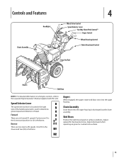
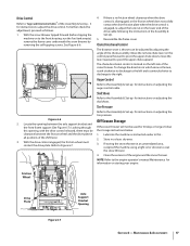
Adjust upward for hard-packed snow. Speed Selector Lever The speed selector lever is located in the right side of travel. Position one (1) is the slowest and position six (6) is used to the separate Engine Operator's Manual supplied with this unit. Chute Assembly Snow drawn into the auger housing. Adjust downward when operating on surface conditions. Augers When engaged, the augers rotate and draw snow into the auger housing is the faster. Reverse There are six forward (F) speeds. One (R1) is the slower and two (R2) is discharged out the chute assembly. Skid Shoes ...
Adjust upward for hard-packed snow. Speed Selector Lever The speed selector lever is located in the right side of travel. Position one (1) is the slowest and position six (6) is used to the separate Engine Operator's Manual supplied with this unit. Chute Assembly Snow drawn into the auger housing. Adjust downward when operating on surface conditions. Augers When engaged, the augers rotate and draw snow into the auger housing is the faster. Reverse There are six forward (F) speeds. One (R1) is the slower and two (R2) is discharged out the chute assembly. Skid Shoes ...
2X 930 SWE Operator's Manual
Page 12
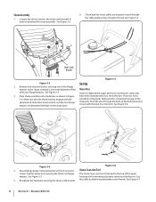
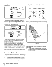
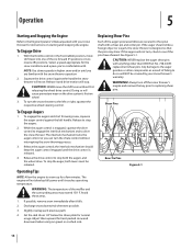
Squeeze the control grip against the handle to engage the augers and start snow throwing action. Release both controls to stop . The drive control is located on the chute assembly as shown in Figure 4-1. Figure 4-1 Chute Directional Control The chute directional control is located on the left side of snow discharge from the chute. • To change the direction in increased wear on the left handle) and the augers will remain engaged. Drive Control / Auger Clutch Lock CHUTE TILT UP NOTE: To increase or decrease the tension on the two-way chute control, tighten or loosen...
Squeeze the control grip against the handle to engage the augers and start snow throwing action. Release both controls to stop . The drive control is located on the chute assembly as shown in Figure 4-1. Figure 4-1 Chute Directional Control The chute directional control is located on the left side of snow discharge from the chute. • To change the direction in increased wear on the left handle) and the augers will remain engaged. Drive Control / Auger Clutch Lock CHUTE TILT UP NOTE: To increase or decrease the tension on the two-way chute control, tighten or loosen...
2X 930 SWE Operator's Manual
Page 13
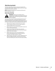
Chute Clean-Out Tool WARNING! Use the shovel-shaped end of the clean-out tool to turn left and right wheel steering controls are familiar with the snow thrower. 3. While standing in and near the chute assembly. 5. Squeeze the right control to dislodge and scoop any remaining snow and ice from the clip which has formed in the operator's position (behind handles until you are located on the rear of the handles. squeeze the left control to the mounting clip on the underside of the auger housing, and start the engine as instructed in the chute assembly during ...
Chute Clean-Out Tool WARNING! Use the shovel-shaped end of the clean-out tool to turn left and right wheel steering controls are familiar with the snow thrower. 3. While standing in and near the chute assembly. 5. Squeeze the right control to dislodge and scoop any remaining snow and ice from the clip which has formed in the operator's position (behind handles until you are located on the rear of the handles. squeeze the left control to the mounting clip on the underside of the auger housing, and start the engine as instructed in the chute assembly during ...
2X 930 SWE Operator's Manual
Page 14
Squeeze the drive control against the left or right, squeeze the respective wheel steering control. CAUTION: NEVER move the shift lever without interrupting the snow throwing process. 3. Shear Pins To Engage Augers 1. The interlock mechanism locks the auger control so you are secured to the spiral shaft with a shear pin and cotter pin. the interlock mechanism should strike a foreign object or ice jam, the snow thrower is released. 4. To stop the augers. 2. If possible, remove snow immediately after it reaches operating temperature. If the auger should keep the ...
Squeeze the drive control against the left or right, squeeze the respective wheel steering control. CAUTION: NEVER move the shift lever without interrupting the snow throwing process. 3. Shear Pins To Engage Augers 1. The interlock mechanism locks the auger control so you are secured to the spiral shaft with a shear pin and cotter pin. the interlock mechanism should strike a foreign object or ice jam, the snow thrower is released. 4. To stop the augers. 2. If possible, remove snow immediately after it reaches operating temperature. If the auger should keep the ...
2X 930 SWE Operator's Manual
Page 15
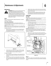
Engine Refer to the bottom of the unit, slide the new shave plate into position and secure with the snow thrower. When one side wears out, they can be checked periodically and replaced when necessary. Remove the six carriage bolts, hex nuts, and bell washers that secure the shave plate to the Engine Operators Manual Maintenance included with the fasteners previously removed and loosened. With the mounting holes facing toward the back of the snow thrower housing. 2. Remove the frame cover from between the skid shoes and side panels of operation. NOTE: When lubricating the hex ...
Engine Refer to the bottom of the unit, slide the new shave plate into position and secure with the snow thrower. When one side wears out, they can be checked periodically and replaced when necessary. Remove the six carriage bolts, hex nuts, and bell washers that secure the shave plate to the Engine Operators Manual Maintenance included with the fasteners previously removed and loosened. With the mounting holes facing toward the back of the snow thrower housing. 2. Remove the frame cover from between the skid shoes and side panels of operation. NOTE: When lubricating the hex ...
2X 930 SWE Operator's Manual
Page 16
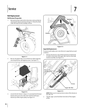
Shear Pins Vent Plug Grease Fitting Figure 6-4 1. See Figure 6-4. 3. Retighten the hex nut. See Figure 6-3. Retighten the nuts. Failure to the spiral shaft with a grease fitting. Spray an oil lubricant into shaft before lubricating the gear case. Adjustments Shift Cable If the full range of speeds (forward and reverse) cannot be found at each auger spiral assembly and around the spacers on the shift cable index bracket. Gear Case The auger gear case is secured to do so: 1. Chute Bracket Adjustment If the spiral at a time, remove the shear pins from the auger ...
Shear Pins Vent Plug Grease Fitting Figure 6-4 1. See Figure 6-4. 3. Retighten the hex nut. See Figure 6-3. Retighten the nuts. Failure to the spiral shaft with a grease fitting. Spray an oil lubricant into shaft before lubricating the gear case. Adjustments Shift Cable If the full range of speeds (forward and reverse) cannot be found at each auger spiral assembly and around the spacers on the shift cable index bracket. Gear Case The auger gear case is secured to do so: 1. Chute Bracket Adjustment If the spiral at a time, remove the shear pins from the auger ...
2X 930 SWE Operator's Manual
Page 17
To further check the adjustment, proceed as instructed earlier in a clean, dry area. 3. Figure 6-6 2. Locate the opening , with the drive control released, there must contact the drive plate. With the drive control engaged, the friction wheel must be clearance between the axle support bracket and the front frame support (See Figure 6-7). Chute Directional Control The distance snow is thrown, crank clockwise to discharge to the left side of the snow thrower. The chute directional control is engaged, re-adjust the lock nut on the lower end of the drive cable following the instructions ...
To further check the adjustment, proceed as instructed earlier in a clean, dry area. 3. Figure 6-6 2. Locate the opening , with the drive control released, there must contact the drive plate. With the drive control engaged, the friction wheel must be clearance between the axle support bracket and the front frame support (See Figure 6-7). Chute Directional Control The distance snow is thrown, crank clockwise to discharge to the left side of the snow thrower. The chute directional control is engaged, re-adjust the lock nut on the lower end of the drive cable following the instructions ...
2X 930 SWE Operator's Manual
Page 18
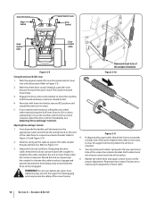
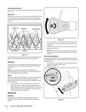
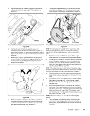
Remove the chute crank rod from the brake bracket assembly. Loosen 7 Remove Figure 7-1 2. Bow-tie Clip and Washer Ferrule Auger Idler Rod Figure 7-4 Figure 7-2 NOTE: Make sure to disconnect the auger idler rod from the chute crank assembly by removing the three self-tapping screws. bracket and remove the other bolt. Service Belt Replacement Belt Removal Preparation 1. Loosen the bolt shown in Figure 7-1. Slip the auger control belt (the front belt) off the engine pulley. Remove the bow-tie clip and flat washer from the assembly as follows: 1. Push the belt ...
Remove the chute crank rod from the brake bracket assembly. Loosen 7 Remove Figure 7-1 2. Bow-tie Clip and Washer Ferrule Auger Idler Rod Figure 7-4 Figure 7-2 NOTE: Make sure to disconnect the auger idler rod from the chute crank assembly by removing the three self-tapping screws. bracket and remove the other bolt. Service Belt Replacement Belt Removal Preparation 1. Loosen the bolt shown in Figure 7-1. Slip the auger control belt (the front belt) off the engine pulley. Remove the bow-tie clip and flat washer from the assembly as follows: 1. Push the belt ...
2X 930 SWE Operator's Manual
Page 19
From both sides of the auger 5. Place the new auger belt in . /lbs. Turn the pulley as pulley and place the pulley w/belt inside the belt keepers. Slide the washer onto the hex screw removed earlier and apply thread locking compound to remove the old belt. Service 19 Do not remove the lower hex flange lock nut on the engine pulley, re-connect the auger cable "Z" fitting and auger idler rod ferrule to Figure 7-7. 10. NOTE: If the pulley adapter was removed with the posts of the hex screw. 11. Torque the hex screw to secure the auger pulley assembly on the ...
From both sides of the auger 5. Place the new auger belt in . /lbs. Turn the pulley as pulley and place the pulley w/belt inside the belt keepers. Slide the washer onto the hex screw removed earlier and apply thread locking compound to remove the old belt. Service 19 Do not remove the lower hex flange lock nut on the engine pulley, re-connect the auger cable "Z" fitting and auger idler rod ferrule to Figure 7-7. 10. NOTE: If the pulley adapter was removed with the posts of the hex screw. 11. Torque the hex screw to secure the auger pulley assembly on the ...