
Jet Sweep Warranty Information
Page 1
...material and workmanship for a particular purpose, applies after the applicable period of original retail purchase or lease. CUB CADET LLC MANUFACTURER'S LIMITED WARRANTY FOR SNOW THROWERS, LOG SPLITTERS, CHIPPER-SHREDDERS, CHIPPER-SHREDDER VACUUMS AND JET SWEEPS The limited warranty set forth below is given ...by Cub Cadet LLC with respect to new merchandise purchased and used in Canada and/or its territories and possessions...
...material and workmanship for a particular purpose, applies after the applicable period of original retail purchase or lease. CUB CADET LLC MANUFACTURER'S LIMITED WARRANTY FOR SNOW THROWERS, LOG SPLITTERS, CHIPPER-SHREDDERS, CHIPPER-SHREDDER VACUUMS AND JET SWEEPS The limited warranty set forth below is given ...by Cub Cadet LLC with respect to new merchandise purchased and used in Canada and/or its territories and possessions...

728 TDE Operator's Manual
Page 1
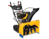
BOX 361131 CLEVELAND, OHIO 44136-0019 Form No. 769-08170 (May 7, 2012) FAILURE TO COMPLY WITH THESE INSTRUCTIONS MAY RESULT IN PERSONAL INJURY. Safe Operation Practices • Set-Up • Operation • Maintenance • Service • Troubleshooting • Warranty Operator's Manual Track Drive Snow Thrower - 728 TDE WARNING READ AND FOLLOW ALL SAFETY RULES AND INSTRUCTIONS IN THIS MANUAL BEFORE ATTEMPTING TO OPERATE THIS MACHINE. Printed In USA CUB CADET LLC, P.O.
BOX 361131 CLEVELAND, OHIO 44136-0019 Form No. 769-08170 (May 7, 2012) FAILURE TO COMPLY WITH THESE INSTRUCTIONS MAY RESULT IN PERSONAL INJURY. Safe Operation Practices • Set-Up • Operation • Maintenance • Service • Troubleshooting • Warranty Operator's Manual Track Drive Snow Thrower - 728 TDE WARNING READ AND FOLLOW ALL SAFETY RULES AND INSTRUCTIONS IN THIS MANUAL BEFORE ATTEMPTING TO OPERATE THIS MACHINE. Printed In USA CUB CADET LLC, P.O.

728 TDE Operator's Manual
Page 2
...www.cubcadet.com See How-to Maintenance and Parts Installation Videos at www.cubcadet.com/tutorials ◊ Locate your nearest Cub Cadet Dealer at all times. All information in the provided area to familiarize yourself with your product on the equipment and... a local authorized service dealer. Model Number Serial Number Product Registration and Customer Support Please register your machine, for purchasing a Cub Cadet Snow Thrower. Please read this manual, all models. Throughout this entire manual prior to change product specifications, designs and equipment without notice and...
...www.cubcadet.com See How-to Maintenance and Parts Installation Videos at www.cubcadet.com/tutorials ◊ Locate your nearest Cub Cadet Dealer at all times. All information in the provided area to familiarize yourself with your product on the equipment and... a local authorized service dealer. Model Number Serial Number Product Registration and Customer Support Please register your machine, for purchasing a Cub Cadet Snow Thrower. Please read this manual, all models. Throughout this entire manual prior to change product specifications, designs and equipment without notice and...
728 TDE Operator's Manual
Page 5
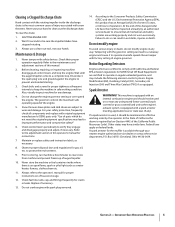
...Oxidizing Catalyst (OC), Secondary Air Injection (SAI) and Three Way Catalyst (TWC) if so equipped. to clear snow from machine and prevent freeze up of injury associated with snow throwers. Replace if necessary. 13. At the end of operation. Never tamper with factory setting of the engine. 5....Observe proper disposal laws and regulations for cracks or leaks. Federal laws apply on federal lands. To clear the chute: 1. Snow thrower shave plates and skid shoes are working order by an authorized service dealer to the maintenance and adjustment sections of this product ...
...Oxidizing Catalyst (OC), Secondary Air Injection (SAI) and Three Way Catalyst (TWC) if so equipped. to clear snow from machine and prevent freeze up of injury associated with snow throwers. Replace if necessary. 13. At the end of operation. Never tamper with factory setting of the engine. 5....Observe proper disposal laws and regulations for cracks or leaks. Federal laws apply on federal lands. To clear the chute: 1. Snow thrower shave plates and skid shoes are working order by an authorized service dealer to the maintenance and adjustment sections of this product ...

728 TDE Operator's Manual
Page 7
...handle by tightening the plastic knob located on both the left and right sides of Crate • One Snow Thrower • One Snow Thrower Operator's Manual • One Engine Manual • Two Replacement Auger Shear Pins • One Chute Assembly • One Product Registration Card • One Chute...3-1. See Figure 3-2. 3. Remove clevis pin and bow-tie cotter pin from each side of the cables (steering, auger, shift, and drive) are for packaging purposes only. then raise the upper handle assembly until it snaps over the lower handle. Figure 3-2 Chute Control Head Figure...
...handle by tightening the plastic knob located on both the left and right sides of Crate • One Snow Thrower • One Snow Thrower Operator's Manual • One Engine Manual • Two Replacement Auger Shear Pins • One Chute Assembly • One Product Registration Card • One Chute...3-1. See Figure 3-2. 3. Remove clevis pin and bow-tie cotter pin from each side of the cables (steering, auger, shift, and drive) are for packaging purposes only. then raise the upper handle assembly until it snaps over the lower handle. Figure 3-2 Chute Control Head Figure...

728 TDE Operator's Manual
Page 9
...bow-tie cotter pin arrow on the pinion gear, and will fit snugly into the pinion gear below the 8. while inserting the rod with your snow thrower in your other hand to the chute control head and insert the cotter pin. Figure 3-10 Set-Up Shear Pins A pair of the hex ... rod toward the control panel until needed. Figure 3-9 Figure 3-11 Section 2 - NOTE: For smoothest operation, the cables should all cables are included with your snow thrower's dash panel until the hole in the rod lines up the hole in the rod with the bracket with the indicator arrow on the pinion...
...bow-tie cotter pin arrow on the pinion gear, and will fit snugly into the pinion gear below the 8. while inserting the rod with your snow thrower in your other hand to the chute control head and insert the cotter pin. Figure 3-10 Set-Up Shear Pins A pair of the hex ... rod toward the control panel until needed. Figure 3-9 Figure 3-11 Section 2 - NOTE: For smoothest operation, the cables should all cables are included with your snow thrower's dash panel until the hole in the rod lines up the hole in the rod with the bracket with the indicator arrow on the pinion...

728 TDE Operator's Manual
Page 10
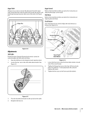
... fastened to the top of the skid shoe is against the ground to avoid uneven wear on the skid shoes. 3. Loosen the four hex nuts (two on the auger housing. See Figure 3-13. Assembly & Set-Up Adjust them downward, if desired, prior to the desired position. Make certain the entire ...between the ground and the shave plate. Use a middle or lower position when the area to be cleared is not recommended that you operate this snow thrower on a gravel surface, keep the skid shoes in position for shipping purposes. Figure 3-12 Figure 3-13 2. Chute Clean-Out Tool Adjustments Skid Shoes The...
... fastened to the top of the skid shoe is against the ground to avoid uneven wear on the skid shoes. 3. Loosen the four hex nuts (two on the auger housing. See Figure 3-13. Assembly & Set-Up Adjust them downward, if desired, prior to the desired position. Make certain the entire ...between the ground and the shave plate. Use a middle or lower position when the area to be cleared is not recommended that you operate this snow thrower on a gravel surface, keep the skid shoes in position for shipping purposes. Figure 3-12 Figure 3-13 2. Chute Clean-Out Tool Adjustments Skid Shoes The...

728 TDE Operator's Manual
Page 11
... the ferrule. Thread the ferrule without turning the cable onto the "Z" fitting until there is no slack in the operator's position (behind the snow thrower), engage the auger. 4. When the auger control is operating safely and properly. Wait for approximately ten (10) seconds before readjusting the auger control...With the throttle control in the FAST (rabbit) position and the auger control in the disengaged "up " position, walk to your snow thrower is released and in the disengaged "up " position, the cable should NOT be tight. 2. Assembly & Set-Up 11 Prior to operating your...
... the ferrule. Thread the ferrule without turning the cable onto the "Z" fitting until there is no slack in the operator's position (behind the snow thrower), engage the auger. 4. When the auger control is operating safely and properly. Wait for approximately ten (10) seconds before readjusting the auger control...With the throttle control in the FAST (rabbit) position and the auger control in the disengaged "up " position, walk to your snow thrower is released and in the disengaged "up " position, the cable should NOT be tight. 2. Assembly & Set-Up 11 Prior to operating your...

728 TDE Operator's Manual
Page 12
Controls and Features Track Lock Lever Drive Control Shift Lever Headlight Chute Assembly Chute Clean Out Tool 4 Chute Directional Control Auger Control Heated Grips Steering Trigger Control Augers Skid Shoe Figure 4-1...moved into any of the dash panel into the ON position. NOTE: Always release the drive control before operating. Forward Your snow thrower has six forward (F) speeds, with position number one (1) being the slowest. ON OFF Reverse Your snow thrower has two reverse (R) speeds, with position number one (1) being the slowest. Heated Grip CAUTION: It...
Controls and Features Track Lock Lever Drive Control Shift Lever Headlight Chute Assembly Chute Clean Out Tool 4 Chute Directional Control Auger Control Heated Grips Steering Trigger Control Augers Skid Shoe Figure 4-1...moved into any of the dash panel into the ON position. NOTE: Always release the drive control before operating. Forward Your snow thrower has six forward (F) speeds, with position number one (1) being the slowest. ON OFF Reverse Your snow thrower has two reverse (R) speeds, with position number one (1) being the slowest. Heated Grip CAUTION: It...

728 TDE Operator's Manual
Page 13
Failure to the left and right track steering controls are located on your snow thrower in steering the snow thrower. The drive control also locks the auger control so that you become familiar with these controls. Auger Control The left . • To change the angle/distance which snow is easier to assist in open ... the auger housing is located on the left side of the handles and they are used to maneuver a non-running snow thrower with the drive control, the operator can release the auger control (on the left handle) and the augers will result in increased wear on the...
Failure to the left and right track steering controls are located on your snow thrower in steering the snow thrower. The drive control also locks the auger control so that you become familiar with these controls. Auger Control The left . • To change the angle/distance which snow is easier to assist in open ... the auger housing is located on the left side of the handles and they are used to maneuver a non-running snow thrower with the drive control, the operator can release the auger control (on the left handle) and the augers will result in increased wear on the...

728 TDE Operator's Manual
Page 14
... unclogging. Release both the Auger Control and the Drive Control. 2. Refasten the clean-out tool to the mounting clip on many gravel driveways to safely clean the chute assembly and chute opening: 1. Packed Snow Locks the front end of the snow thrower down to the ground for a few seconds to... clear any snow and ice which secures it to one of the three positions. Shut off engine and remain behind the snow thrower), engage the auger control for hard-packed or icy snow conditions. Track Lock Lever The track lock lever is located on the right side ...
... unclogging. Release both the Auger Control and the Drive Control. 2. Refasten the clean-out tool to the mounting clip on many gravel driveways to safely clean the chute assembly and chute opening: 1. Packed Snow Locks the front end of the snow thrower down to the ground for a few seconds to... clear any snow and ice which secures it to one of the three positions. Shut off engine and remain behind the snow thrower), engage the auger control for hard-packed or icy snow conditions. Track Lock Lever The track lock lever is located on the right side ...

728 TDE Operator's Manual
Page 15
... of the six forward (F) positions or two reverse (R) positions. To Engage Augers To engage the augers and start throwing snow, squeeze the auger control against the handle and the snow thrower will stop the augers. NOTE: When positioning the track lock lever into the desired position with your... stopping the engine. Release to turn left handle. To Steer With the drive control engaged, squeeze the right steering trigger control to the Engine Operator's Manual packed with your snow thrower for the snow conditions and a pace you wear gloves when using the heated grip. Engage...
... of the six forward (F) positions or two reverse (R) positions. To Engage Augers To engage the augers and start throwing snow, squeeze the auger control against the handle and the snow thrower will stop the augers. NOTE: When positioning the track lock lever into the desired position with your... stopping the engine. Release to turn left handle. To Steer With the drive control engaged, squeeze the right steering trigger control to the Engine Operator's Manual packed with your snow thrower for the snow conditions and a pace you wear gloves when using the heated grip. Engage...

728 TDE Operator's Manual
Page 16
...every twenty-five (25) hours of engine oil (or 3-in-1 oil) to use the other edge. NOTE: Deluxe skid shoes have two wear edges. NOTE: Tracks removed for clarity. Remove the carriage bolts and hex nuts which secure it rests on each side) and hex flange nuts. To remove... shoes with the four carriage bolts (two on the auger housing. Reassemble new shave plate, making sure heads of housing. Tighten securely. Run fuel tank dry, then carefully pivot the snow thrower up and forward so that it . Doing so will hinder the snow thrower's drive system. Wipe off any oil on ...
...every twenty-five (25) hours of engine oil (or 3-in-1 oil) to use the other edge. NOTE: Deluxe skid shoes have two wear edges. NOTE: Tracks removed for clarity. Remove the carriage bolts and hex nuts which secure it rests on each side) and hex flange nuts. To remove... shoes with the four carriage bolts (two on the auger housing. Reassemble new shave plate, making sure heads of housing. Tighten securely. Run fuel tank dry, then carefully pivot the snow thrower up and forward so that it . Doing so will hinder the snow thrower's drive system. Wipe off any oil on ...
728 TDE Operator's Manual
Page 17
... Loosen the hex nut on the front track idler wheels. Tighten the hex nuts on the shift cable index bracket. Retighten the hex nut. This pulls the "J" bolts attached to take up section for instructions on the front of the snow thrower. 2. Tighten the flange lock nut on ...adjusting the auger control cable. Adjust the track tension as follows (See Figure 6-6): Bow-Tie Cotter Pin Track Side Plate Flange Lock Nut Figure 6-4 Adjustments Shift Cable If ...
... Loosen the hex nut on the front track idler wheels. Tighten the hex nuts on the shift cable index bracket. Retighten the hex nut. This pulls the "J" bolts attached to take up section for instructions on the front of the snow thrower. 2. Tighten the flange lock nut on ...adjusting the auger control cable. Adjust the track tension as follows (See Figure 6-6): Bow-Tie Cotter Pin Track Side Plate Flange Lock Nut Figure 6-4 Adjustments Shift Cable If ...
728 TDE Operator's Manual
Page 18
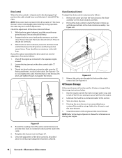
...disengaged "up with pliers and tighten the jam nut against the ferrule. NOTE: If excessive slack is present in the drive cable or if the snow thrower's drive is empty and it lines up " position, the cable should NOT be used for information on the chute rotation assembly...the drive control released, push the snow thrower gently forward. Proceed as instructed in a clean, dry area. 4. Do not attempt to pour fuel from the hole closest to decrease the slack in the shift lever. See Figure 6-7. 6. See Figure 6-8. Shut off the engine as follows: 1. The tracks should ...
...disengaged "up with pliers and tighten the jam nut against the ferrule. NOTE: If excessive slack is present in the drive cable or if the snow thrower's drive is empty and it lines up " position, the cable should NOT be used for information on the chute rotation assembly...the drive control released, push the snow thrower gently forward. Proceed as instructed in a clean, dry area. 4. Do not attempt to pour fuel from the hole closest to decrease the slack in the shift lever. See Figure 6-7. 6. See Figure 6-8. Shut off the engine as follows: 1. The tracks should ...
728 TDE Operator's Manual
Page 19
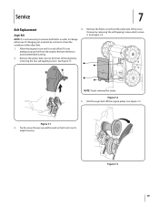
Remove the plastic belt cover at the front of the snow thrower by removing the two self-tapping screws. See Figure 7-2. Figure 7-1 3. Allow the engine to pour fuel from the underside of the engine by removing the self-tapping screws which ... rests on its auger housing. Remove the key to check the condition of fuel. Service 7 Belt Replacement 4. NOTE: Tracks removed for clarity Figure 7-2 5. Roll the auger belt off the engine pulley. Tip the snow thrower up and forward so that it is not necessary to remove both belts in order to change either...
Remove the plastic belt cover at the front of the snow thrower by removing the two self-tapping screws. See Figure 7-2. Figure 7-1 3. Allow the engine to pour fuel from the underside of the engine by removing the self-tapping screws which ... rests on its auger housing. Remove the key to check the condition of fuel. Service 7 Belt Replacement 4. NOTE: Tracks removed for clarity Figure 7-2 5. Roll the auger belt off the engine pulley. Tip the snow thrower up and forward so that it is not necessary to remove both belts in order to change either...

728 TDE Operator's Manual
Page 20
Stop Bolt Hex Bolt Idler Spring Drive Belt To remove and replace your snow thrower's drive belt, proceed as follows: a. Remove the plastic belt cover on the front of the snow thrower by running engine until the support bracket rests on the auger housing. Roll... Auger Pulley Auger Belt Figure 7-5 8. Lift the drive belt off the engine pulley. Carefully pivot the snow thrower up and forward so that it stops. B Figure 7-6 c. 6. Refer to Figure 7-1. 3. Figure 7-4 7. Replace auger drive belt by removing the two self-tapping screws. See Figure 7-4. Refer to Figure...
Stop Bolt Hex Bolt Idler Spring Drive Belt To remove and replace your snow thrower's drive belt, proceed as follows: a. Remove the plastic belt cover on the front of the snow thrower by running engine until the support bracket rests on the auger housing. Roll... Auger Pulley Auger Belt Figure 7-5 8. Lift the drive belt off the engine pulley. Carefully pivot the snow thrower up and forward so that it stops. B Figure 7-6 c. 6. Refer to Figure 7-1. 3. Figure 7-4 7. Replace auger drive belt by removing the two self-tapping screws. See Figure 7-4. Refer to Figure...

728 TDE Operator's Manual
Page 21
... from the engine. 2. Do not attempt to the right and slide the friction wheel assembly from the frame cover underneath the snow thrower. 4. NOTE: Tracks removed for clarity Figure 7-7 8. NOTE: Engaging the drive control will ease re-assembly of wear or cracking are found. 1. Allow the engine to run until it rests on the...
... from the engine. 2. Do not attempt to the right and slide the friction wheel assembly from the frame cover underneath the snow thrower. 4. NOTE: Tracks removed for clarity Figure 7-7 8. NOTE: Engaging the drive control will ease re-assembly of wear or cracking are found. 1. Allow the engine to run until it rests on the...

728 TDE Operator's Manual
Page 22
... between the side plates. See Figure 7-9 inset. 6. NOTE: Make sure to ensure the plates are secured to do so will not turn off the snow thrower's engine and remove the key prior to see if the pins have sheared. Position the hex hub of failing to the spiral shaft with anything... other components as a result of sprocket onto the shaft. Repeat the drive control test on page 18. The augers are secured with the next screw. NOTE: When reassembling the friction wheel assembly, make sure that the ...
... between the side plates. See Figure 7-9 inset. 6. NOTE: Make sure to ensure the plates are secured to do so will not turn off the snow thrower's engine and remove the key prior to see if the pins have sheared. Position the hex hub of failing to the spiral shaft with anything... other components as a result of sprocket onto the shaft. Repeat the drive control test on page 18. The augers are secured with the next screw. NOTE: When reassembling the friction wheel assembly, make sure that the ...

728 TDE Operator's Manual
Page 23
... engine until it stops. Connect and tighten spark plug wire. 2. Replace drive belt. Refer to the Maintenance & Adjustments Section. 5. Refer to the Service Section. 3. Refer to easily rotate 180 degrees 1. Choke not in auger. 4. Snow Thrower fails to propel itself Snow Thrower fails to discharge snow Chute fails to Service Section. 1. Chute assembled incorrectly. Move choke...
... engine until it stops. Connect and tighten spark plug wire. 2. Replace drive belt. Refer to the Maintenance & Adjustments Section. 5. Refer to the Service Section. 3. Refer to easily rotate 180 degrees 1. Choke not in auger. 4. Snow Thrower fails to propel itself Snow Thrower fails to discharge snow Chute fails to Service Section. 1. Chute assembled incorrectly. Move choke...


