User Manual
Page 1
User's Manual Power Distribution Unit
User's Manual Power Distribution Unit

User Manual
Page 2
Table of Contents Model List 1 PDU Naming Convention 1 Package Contents 2 Safety Precautions 2 Installation 3 Horizontal Installation 3 Vertical Installation with Brackets ... 4 Vertical Installation Keyhole Mounts (0U models only) ... 5 Cord Retention Tray installation ...... 5 Meter Configuration 5 Electrical Installation 6 Troubleshooting 6 Product Features Technical Specification 7 Basic Series (1U 20A 7 Basic Series (1U 30A 8 Basic Series (0U 10A 9 Basic Series (0U 20A 10 Basic Series (0U 30A 11 Metered Series (0U 20A 12 Metered Series (0U 30A 13 Warranty & Service 14
Table of Contents Model List 1 PDU Naming Convention 1 Package Contents 2 Safety Precautions 2 Installation 3 Horizontal Installation 3 Vertical Installation with Brackets ... 4 Vertical Installation Keyhole Mounts (0U models only) ... 5 Cord Retention Tray installation ...... 5 Meter Configuration 5 Electrical Installation 6 Troubleshooting 6 Product Features Technical Specification 7 Basic Series (1U 20A 7 Basic Series (1U 30A 8 Basic Series (0U 10A 9 Basic Series (0U 20A 10 Basic Series (0U 30A 11 Metered Series (0U 20A 12 Metered Series (0U 30A 13 Warranty & Service 14
User Manual
Page 3
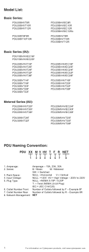
Rack Space: 4. Plug Type: 6. Example 8R NET 1 For information on Cyberpower products, visit www.cyberpower.com Model List: Basic Series: PDU20BHVT8R PDU20BHVT10R PDU20BHVT12R PDU30BT8F8R PDU30BT10F10R Basic Series (0U): PDU10BVHVIEC16F PDU10BVHVIEC20F PDU20BVHVT16F PDU20BVHVT20F PDU20BVHVT24F ... Naming Convention: PDU XX M V HV T F R NET 1 23 4 5 6 7 8 1. Series: 3. Outlet Number Rear 8. Network Management Amperage - 15A, 20A, 30A B: =Basic M: =Metered SW: = Switched NULL: =Horizontal V:= Vertical NULL: =120V HV:= High Voltage - 200V to 230V NULL: =NEMA 5-15P / 5-20P T:...
Rack Space: 4. Plug Type: 6. Example 8R NET 1 For information on Cyberpower products, visit www.cyberpower.com Model List: Basic Series: PDU20BHVT8R PDU20BHVT10R PDU20BHVT12R PDU30BT8F8R PDU30BT10F10R Basic Series (0U): PDU10BVHVIEC16F PDU10BVHVIEC20F PDU20BVHVT16F PDU20BVHVT20F PDU20BVHVT24F ... Naming Convention: PDU XX M V HV T F R NET 1 23 4 5 6 7 8 1. Series: 3. Outlet Number Rear 8. Network Management Amperage - 15A, 20A, 30A B: =Basic M: =Metered SW: = Switched NULL: =Horizontal V:= Vertical NULL: =120V HV:= High Voltage - 200V to 230V NULL: =NEMA 5-15P / 5-20P T:...
User Manual
Page 4
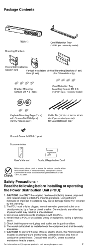
... information on a circuit protected by model) Horizontal Installation Used (1 set) Vertical Installation Vertical Mounting Brackets (1 set) Used (1 set) (for 0U models only) Bracket Mounting Screws M4 X 6 (4pcs) Cord Retention Tray Mounting Screws M3 X 6 (4/8/12/16 pcs - Do not use extension cords or adapters with Screws M4 X 6 (2pcs) (for Cord Retention Tray Ground Screw M5 X 6 (1 pcs) Documentation: User Manual DistriPbuotwioenr Unit User's Manual Product Registration Card Product Registration Card...
... information on a circuit protected by model) Horizontal Installation Used (1 set) Vertical Installation Vertical Mounting Brackets (1 set) Used (1 set) (for 0U models only) Bracket Mounting Screws M4 X 6 (4pcs) Cord Retention Tray Mounting Screws M3 X 6 (4/8/12/16 pcs - Do not use extension cords or adapters with Screws M4 X 6 (2pcs) (for Cord Retention Tray Ground Screw M5 X 6 (1 pcs) Documentation: User Manual DistriPbuotwioenr Unit User's Manual Product Registration Card Product Registration Card...
User Manual
Page 5
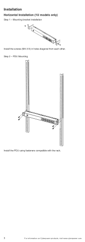
PDU Mounting Install the PDU using fasteners compatible with the rack. 3 For information on Cyberpower products, visit www.cyberpower.com Step 2 - Mounting bracket installation Install the screws (M4 X 6) in holes diagonal from each other. Installation Horizontal Installation (1U models only) Step 1 -
PDU Mounting Install the PDU using fasteners compatible with the rack. 3 For information on Cyberpower products, visit www.cyberpower.com Step 2 - Mounting bracket installation Install the screws (M4 X 6) in holes diagonal from each other. Installation Horizontal Installation (1U models only) Step 1 -
User Manual
Page 6
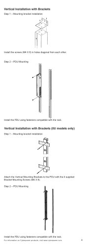
Vertical Installation with the rack. PDU Mounting Install the PDU using fasteners compatible with Brackets Step 1 - For information on Cyberpower products, visit www.cyberpower.com 4 Step 2 - Mounting bracket installation Install the screws (M4 X 6) in holes diagonal from each other. Vertical Installation with the rack. PDU Mounting Install the PDU using fasteners compatible with Brackets (0U models only) Step 1 - Mounting bracket installation Attach the Vertical Mounting Brackets to the PDU with the 4 supplied Bracket Mounting Screws (M4 X 6). Step 2 -
Vertical Installation with the rack. PDU Mounting Install the PDU using fasteners compatible with Brackets Step 1 - For information on Cyberpower products, visit www.cyberpower.com 4 Step 2 - Mounting bracket installation Install the screws (M4 X 6) in holes diagonal from each other. Vertical Installation with the rack. PDU Mounting Install the PDU using fasteners compatible with Brackets (0U models only) Step 1 - Mounting bracket installation Attach the Vertical Mounting Brackets to the PDU with the 4 supplied Bracket Mounting Screws (M4 X 6). Step 2 -
User Manual
Page 7
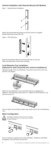
...Cyberpower products, visit www.cyberpower.com Keyhole Mount installation Attach the Keyhole Mounting Pegs to the Cord Retention Tray. Insert and slide down to the PDU with the 2 supplied Bracket Mounting Screws (M4 X 6). Use the Cable Ties provided to fasten each power cord to the PDU with the 4 supplied Cord Retention Tray Mounting Screws (M3 X 6). Use... gently remove the LED Meter. Attach the Cord Retention Tray to lock firmly into the PDU. 5 For information on it. Step 2 - Meter Configuration ! Tighten the Cord Retention Tray with Keyhole Mounts (0U Models) Step 1 -
...Cyberpower products, visit www.cyberpower.com Keyhole Mount installation Attach the Keyhole Mounting Pegs to the Cord Retention Tray. Insert and slide down to the PDU with the 2 supplied Bracket Mounting Screws (M4 X 6). Use the Cable Ties provided to fasten each power cord to the PDU with the 4 supplied Cord Retention Tray Mounting Screws (M3 X 6). Use... gently remove the LED Meter. Attach the Cord Retention Tray to lock firmly into the PDU. 5 For information on it. Step 2 - Meter Configuration ! Tighten the Cord Retention Tray with Keyhole Mounts (0U Models) Step 1 -
User Manual
Page 8
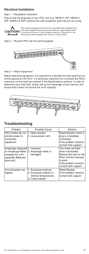
... circuit/main with fuse or circuit breaker protection. Loose power cord Amperage displayed 1. Sustained overload 2. The meter will be placing on Cyberpower products, visit www.cyberpower.com 6 If the problem remains contact tech support. Electrical Installation Step 1 - Step 2 - Troubleshooting Problem PDU Outlets do not provide power to exceed the PDU's maximum current load (as outlined in a shock hazard. Reset Breaker. Excessive ambient...
... circuit/main with fuse or circuit breaker protection. Loose power cord Amperage displayed 1. Sustained overload 2. The meter will be placing on Cyberpower products, visit www.cyberpower.com 6 If the problem remains contact tech support. Electrical Installation Step 1 - Step 2 - Troubleshooting Problem PDU Outlets do not provide power to exceed the PDU's maximum current load (as outlined in a shock hazard. Reset Breaker. Excessive ambient...
User Manual
Page 9
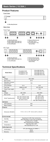
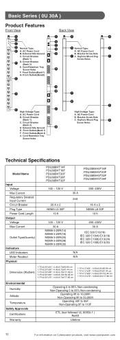
...External Site Ground F. Back Outlets (IEC 320 C13) C. Cord Retention Tray Screw Holes Technical Specifications Model Name Input Voltage Max Current Regulatory Derated Input Current Circuit Breaker Plug Type Power Cord Length Output Voltage Max Current Outlet Type(Quantity) Indicators LED Indicators Meter ...to 95F Non-Operating 5F to 113F ETL (test followed UL 60950-1 ) RoHS Lifetime 7 For information on Cyberpower products, visit www.cyberpower.com Cord Retention Tray Screw Holes AF B A. Circuit Breaker IEC Type C DEF G E. AC Power Cord G. Basic Series ( 1U 20A ) Product...
...External Site Ground F. Back Outlets (IEC 320 C13) C. Cord Retention Tray Screw Holes Technical Specifications Model Name Input Voltage Max Current Regulatory Derated Input Current Circuit Breaker Plug Type Power Cord Length Output Voltage Max Current Outlet Type(Quantity) Indicators LED Indicators Meter ...to 95F Non-Operating 5F to 113F ETL (test followed UL 60950-1 ) RoHS Lifetime 7 For information on Cyberpower products, visit www.cyberpower.com Cord Retention Tray Screw Holes AF B A. Circuit Breaker IEC Type C DEF G E. AC Power Cord G. Basic Series ( 1U 20A ) Product...
User Manual
Page 10
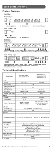
... (Bank 1) F.External Site Ground G.AC Power Cord H.Cord Retention Tray Screw Holes Technical Specifications Model Name Input Voltage Max Current Regulatory Derated Input Current Circuit Breaker Plug Type Power Cord Length Output Voltage Max Current Outlet Type(Quantity) Indicators LED Indicators Meter Readout Physical PDU30BT8F8R PDU30BT10F10R PDU30BHVT8R PDU30BHVT10R PDU30BHVT12R 100 ~ 125 V... 50,000ft Operating 32F to 95F Non-Operating 5F to 113F ETL (test followed UL 60950-1 ) RoHS Lifetime For information on Cyberpower products, visit www.cyberpower.com 8 Mounting Bracket C B.
... (Bank 1) F.External Site Ground G.AC Power Cord H.Cord Retention Tray Screw Holes Technical Specifications Model Name Input Voltage Max Current Regulatory Derated Input Current Circuit Breaker Plug Type Power Cord Length Output Voltage Max Current Outlet Type(Quantity) Indicators LED Indicators Meter Readout Physical PDU30BT8F8R PDU30BT10F10R PDU30BHVT8R PDU30BHVT10R PDU30BHVT12R 100 ~ 125 V... 50,000ft Operating 32F to 95F Non-Operating 5F to 113F ETL (test followed UL 60950-1 ) RoHS Lifetime For information on Cyberpower products, visit www.cyberpower.com 8 Mounting Bracket C B.
User Manual
Page 11
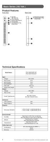
...Ground C D. Front Outlets E. Cord Retention Tray E Screw Holes A. Keyhole Mount Peg Screw Holes B D B A E Technical Specifications Model Name Input Voltage Max Current Input Current Circuit Breaker Plug Type Power Cord Length Output Voltage Max Current Outlet Type(Quantity) Indicators LED Indicators Meter Readout Physical Dimension (WxDxH) Environmental Humidity Altitude ...0ft to 50,000ft Operating 32F to 95F Non-Operating 5F to 113F ETL (test followed UL 60950-1 ) RoHS Lifetime 9 For information on Cyberpower products, visit www.cyberpower.com Bracket Screw Hole A B.
...Ground C D. Front Outlets E. Cord Retention Tray E Screw Holes A. Keyhole Mount Peg Screw Holes B D B A E Technical Specifications Model Name Input Voltage Max Current Input Current Circuit Breaker Plug Type Power Cord Length Output Voltage Max Current Outlet Type(Quantity) Indicators LED Indicators Meter Readout Physical Dimension (WxDxH) Environmental Humidity Altitude ...0ft to 50,000ft Operating 32F to 95F Non-Operating 5F to 113F ETL (test followed UL 60950-1 ) RoHS Lifetime 9 For information on Cyberpower products, visit www.cyberpower.com Bracket Screw Hole A B.
User Manual
Page 12
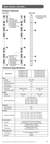
... Front View A A B B Twist Type: C A. Circuit Breaker C. Front Outlets E. Front Outlets F. Cord Retention Tray Screw Holes F Technical Specifications Model Name Input Voltage Max Current Regulatory Derated Input Current Circuit Breaker Plug Type Power Cord Length Output Voltage Max Current Outlet Type(Quantity) Indicators LED Indicators Meter Readout Physical Dimension (WxDxH) Environmental Humidity Altitude Temperature Safety Approvals Certifications Warranty PDU20BVHVT16F...
... Front View A A B B Twist Type: C A. Circuit Breaker C. Front Outlets E. Front Outlets F. Cord Retention Tray Screw Holes F Technical Specifications Model Name Input Voltage Max Current Regulatory Derated Input Current Circuit Breaker Plug Type Power Cord Length Output Voltage Max Current Outlet Type(Quantity) Indicators LED Indicators Meter Readout Physical Dimension (WxDxH) Environmental Humidity Altitude Temperature Safety Approvals Certifications Warranty PDU20BVHVT16F...
User Manual
Page 13
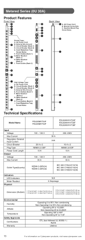
... Tray Screw Holes C B C High Voltage Type: A. Circuit Breaker (Bank 1) F D. External Site Ground G E . Keyhole Mount Peg B Screw Holes Technical Specifications Model Name Input Voltage Max Current Regulatory Derated Input Current Circuit Breaker Plug Type Power Cord Length Output Voltage Max Current Outlet Type(Quantity) Indicators LED Indicators Meter Readout Physical PDU30BVT14F PDU30BVT16F PDU30BVT20F PDU30BVT28F PDU30BVT32F 100 ~ 125...
... Tray Screw Holes C B C High Voltage Type: A. Circuit Breaker (Bank 1) F D. External Site Ground G E . Keyhole Mount Peg B Screw Holes Technical Specifications Model Name Input Voltage Max Current Regulatory Derated Input Current Circuit Breaker Plug Type Power Cord Length Output Voltage Max Current Outlet Type(Quantity) Indicators LED Indicators Meter Readout Physical PDU30BVT14F PDU30BVT16F PDU30BVT20F PDU30BVT28F PDU30BVT32F 100 ~ 125...
User Manual
Page 14
...Hole B. Front Outlets A E. AC Power Cord B. External Site Ground D. Circuit Breaker C G C. Cord Retention Tray G Screw Holes G Technical Specifications Model Name Input Voltage Max Current Regulatory Derated Input Current Circuit Breaker Plug Type Power Cord Length Output Voltage Max Current PDU20MVHVT20F PDU20MVHVT30F PDU20MVHVT38F ...to 50,000ft Operating 32F to 95F Non-Operating 5F to 113F ETL (test followed UL 60950-1 ) RoHS Lifetime For information on Cyberpower products, visit www.cyberpower.com 12 Front Outlets G. Meter Series ( 0U 20A ) Product Features ...
...Hole B. Front Outlets A E. AC Power Cord B. External Site Ground D. Circuit Breaker C G C. Cord Retention Tray G Screw Holes G Technical Specifications Model Name Input Voltage Max Current Regulatory Derated Input Current Circuit Breaker Plug Type Power Cord Length Output Voltage Max Current PDU20MVHVT20F PDU20MVHVT30F PDU20MVHVT38F ...to 50,000ft Operating 32F to 95F Non-Operating 5F to 113F ETL (test followed UL 60950-1 ) RoHS Lifetime For information on Cyberpower products, visit www.cyberpower.com 12 Front Outlets G. Meter Series ( 0U 20A ) Product Features ...
User Manual
Page 15
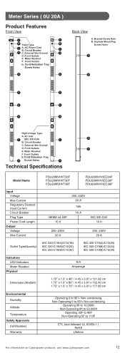
...Power Cord F B. Keyhole Mount Peg C Screw Holes D I B E C F G I H G I (Bank 2) H. Cord Retention Tray Screw Holes F. AC Power Cord B. AC Power Cord B. External Site Ground E. Meter Readout (Bank 2) F I Technical Specifications Model Name Input Voltage Max Current Regulatory Derated Input Current Circuit Breaker Plug Type Power Cord Length Output...to 95F Non-Operating 5F to 113F ETL (test followed UL 60950-1 ) RoHS Lifetime 13 For information on Cyberpower products, visit www.cyberpower.com Front Outlets (Bank 1) F. Cord Retention Tray B Screw Holes E I ....
...Power Cord F B. Keyhole Mount Peg C Screw Holes D I B E C F G I H G I (Bank 2) H. Cord Retention Tray Screw Holes F. AC Power Cord B. AC Power Cord B. External Site Ground E. Meter Readout (Bank 2) F I Technical Specifications Model Name Input Voltage Max Current Regulatory Derated Input Current Circuit Breaker Plug Type Power Cord Length Output...to 95F Non-Operating 5F to 113F ETL (test followed UL 60950-1 ) RoHS Lifetime 13 For information on Cyberpower products, visit www.cyberpower.com Front Outlets (Bank 1) F. Cord Retention Tray B Screw Holes E I ....

User Manual
Page 16
... and Request a Claim Number. 3. CyberPower will repair or replace it . Who Pays For Shipping? We pay when we send items to us at CyberPower's expense, or, if CyberPower is Providing this "Warranty"). Product Registration Thank you for instructions. 2. Feel free to be bound by and become a party to the terms and conditions of Connected Equipment, a repair cost estimate for...
... and Request a Claim Number. 3. CyberPower will repair or replace it . Who Pays For Shipping? We pay when we send items to us at CyberPower's expense, or, if CyberPower is Providing this "Warranty"). Product Registration Thank you for instructions. 2. Feel free to be bound by and become a party to the terms and conditions of Connected Equipment, a repair cost estimate for...

User Manual
Page 17
... and exclusive remedies of the most current electrical code), without the use with the Product, such as a result of the failure or the restoration of data or records, or the reinstallation of any license, instruction manual, or warnings provided with the Product and the equipment connected to it. 4. Any such installation voids the Limited Warranty. 3. The Product must...
... and exclusive remedies of the most current electrical code), without the use with the Product, such as a result of the failure or the restoration of data or records, or the reinstallation of any license, instruction manual, or warnings provided with the Product and the equipment connected to it. 4. Any such installation voids the Limited Warranty. 3. The Product must...
Datasheet
Page 1
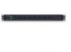
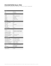
... NEMA L5-30P twist lock plug, with unfiltered electrical pass-through. It can be mounted either horizontally or vertically, includes a cord retention tray and is free of defects in design, assembly, material and workmanship. The CyberPower 16-outlet (8 Front/8 Rear) rack mount basic power distribution unit (PDU30BT8F8R) provides 120V 30A output. Designed for datacenters and other...
... NEMA L5-30P twist lock plug, with unfiltered electrical pass-through. It can be mounted either horizontally or vertically, includes a cord retention tray and is free of defects in design, assembly, material and workmanship. The CyberPower 16-outlet (8 Front/8 Rear) rack mount basic power distribution unit (PDU30BT8F8R) provides 120V 30A output. Designed for datacenters and other...
Datasheet
Page 2
... Installation Supported Yes Yes 2 sets (L-short, L-long) 17.5 x 1.75 x 2.25 6.0 32°F to 95°F / 0°C to 35°C 0% - 95% non-condensing 5°F to 113°F / -15°C to equipment. CyberPower reserves the right to change, without prior notice, product offerings or specifications. All rights reserved. GENERAL Type Phase INPUT Voltage Current Frequency Plug Type Plug Style Cord...
... Installation Supported Yes Yes 2 sets (L-short, L-long) 17.5 x 1.75 x 2.25 6.0 32°F to 95°F / 0°C to 35°C 0% - 95% non-condensing 5°F to 113°F / -15°C to equipment. CyberPower reserves the right to change, without prior notice, product offerings or specifications. All rights reserved. GENERAL Type Phase INPUT Voltage Current Frequency Plug Type Plug Style Cord...