Product Manual
Page 2
... Guide Overview 6 Using the Installation Guide ...6 Using the Embedded Web Interface User Guide 6 Intended Audience...7 D-Link DES-3010PA Installation Guide 8 Device Description ...9 Viewing the Device ...10 Device Front Panel ...10 Ports Description ...11 10/100Base-TX Fast......21 Installing the Device ...22 Desktop or Shelf Installation ...22 Rack Installation ...22 Wall Installation...25 Connecting the Device ...26 Connecting the Switch to a Terminal ...26 AC Power Connection ...27 Starting and Configuring the Device 28 Configuring the Terminal ...29 Installation Procedure ...29 Device ...
... Guide Overview 6 Using the Installation Guide ...6 Using the Embedded Web Interface User Guide 6 Intended Audience...7 D-Link DES-3010PA Installation Guide 8 Device Description ...9 Viewing the Device ...10 Device Front Panel ...10 Ports Description ...11 10/100Base-TX Fast......21 Installing the Device ...22 Desktop or Shelf Installation ...22 Rack Installation ...22 Wall Installation...25 Connecting the Device ...26 Connecting the Switch to a Terminal ...26 AC Power Connection ...27 Starting and Configuring the Device 28 Configuring the Terminal ...29 Installation Procedure ...29 Device ...
Product Manual
Page 3
... 37 Startup Procedures ...41 Startup Menu Procedures ...41 Software Download and Reboot ...42 D-Link DES-3010PA EWS User Guide 46 Getting Started...47 Starting the D-Link Embedded Web Interface 48 Understanding the D-Link Embedded Web Interface 50 Device Representation...51 Using the D-Link Embedded Web Interface Management Buttons 51 Using Screen and Table Options 53 Adding...
... 37 Startup Procedures ...41 Startup Menu Procedures ...41 Software Download and Reboot ...42 D-Link DES-3010PA EWS User Guide 46 Getting Started...47 Starting the D-Link Embedded Web Interface 48 Understanding the D-Link Embedded Web Interface 50 Device Representation...51 Using the D-Link Embedded Web Interface Management Buttons 51 Using Screen and Table Options 53 Adding...
Product Manual
Page 5
D-Link DES-3010FA/GA User Guide Configuring Quality of Service 187 VPT Classification Information ...187 CoS Services ...188 Configuring Quality of Service General Settings 189 Defining QoS ...
D-Link DES-3010FA/GA User Guide Configuring Quality of Service 187 VPT Classification Information ...187 CoS Services ...188 Configuring Quality of Service General Settings 189 Defining QoS ...
Product Manual
Page 6
... Viewing RMON Statistics...241 Resetting RMON Statistics Counters...242 Configuring RMON History ...243 Defining RMON Alarms ...249 Appendix A, Device Specifications & Features 251 Hardware Specifications ...251 DES-3010PA Features...252 Appendix B, Troubleshooting ...258 Problem Solving ...258 Troubleshooting Solutions...258 Contacting D-Link Technical Support 261 Warranty ...288 Product Registration ...292 International Offices ...293 Page 5
... Viewing RMON Statistics...241 Resetting RMON Statistics Counters...242 Configuring RMON History ...243 Defining RMON Alarms ...249 Appendix A, Device Specifications & Features 251 Hardware Specifications ...251 DES-3010PA Features...252 Appendix B, Troubleshooting ...258 Problem Solving ...258 Troubleshooting Solutions...258 Contacting D-Link Technical Support 261 Warranty ...288 Product Registration ...292 International Offices ...293 Page 5

Product Manual
Page 7
... buttons, as well as information about configuring Link Aggregated Groups and LACP. • Section 10. Configuring IP Information - Page 6 D-Link DES-3010PA User Guide Preface This preface provides an overview to the D-Link DES-3010PA User Guide, and includes the following sections: • D-Link DES-3010PA User Guide Overview • Intended Audience D-Link DES-3010PA User Guide Overview This user guide is divided...
... buttons, as well as information about configuring Link Aggregated Groups and LACP. • Section 10. Configuring IP Information - Page 6 D-Link DES-3010PA User Guide Preface This preface provides an overview to the D-Link DES-3010PA User Guide, and includes the following sections: • D-Link DES-3010PA User Guide Overview • Intended Audience D-Link DES-3010PA User Guide Overview This user guide is divided...
Product Manual
Page 10
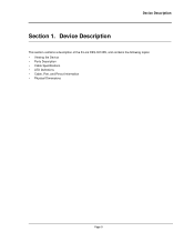
Device Description This section contains a description of the D-Link DES-3010PA, and contains the following topics: • Viewing the Device • Ports Description • Cable Specifications • LED Definitions • Cable, Port, and Pinout Information • Physical Dimensions Page 9 Device Description Section 1.
Device Description This section contains a description of the D-Link DES-3010PA, and contains the following topics: • Viewing the Device • Ports Description • Cable Specifications • LED Definitions • Cable, Port, and Pinout Information • Physical Dimensions Page 9 Device Description Section 1.

Product Manual
Page 11
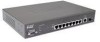
...configuration is used to connect the device to the console managing the device. • 1000Base-T Copper port - Figure 1: D-Link DES-3010PA Front Panel The device front panel is designated on each port of the front panel are designated as port 10. •... device's front panel surface. Device management is an 10 port managed switch. Resets the device. Device Front Panel The following figure illustrates the front panel. D-Link DES-3010PA User Guide Viewing the Device The D-Link DES-3010PA Fast Ethernet Switch is performed using an Embedded Web Server (EWS) or through a Command...
...configuration is used to connect the device to the console managing the device. • 1000Base-T Copper port - Figure 1: D-Link DES-3010PA Front Panel The device front panel is designated on each port of the front panel are designated as port 10. •... device's front panel surface. Device management is an 10 port managed switch. Resets the device. Device Front Panel The following figure illustrates the front panel. D-Link DES-3010PA User Guide Viewing the Device The D-Link DES-3010PA Fast Ethernet Switch is performed using an Embedded Web Server (EWS) or through a Command...
Product Manual
Page 12
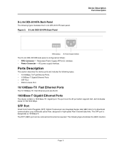
The port is configured as follows. • RPS Connector - The following figure illustrates the D-Link DES-3010 PA back panel. D-Link DES-3010PA Back Panel The following figure illustrates the GBIC insertion. AC power supply interface. Ports Description This ...100Base-TX Fast Ethernet ports are integrated duplex data GBIC links for bi-directional communication over multimode optical fiber, designed for high-speed Fiber Channel data links. Figure 2: D-Link DES-3010PA Back Panel Device Description Ports Description The D-Link DES-3010PA back panel is an RJ-45 port which supports half...
The port is configured as follows. • RPS Connector - The following figure illustrates the D-Link DES-3010 PA back panel. D-Link DES-3010PA Back Panel The following figure illustrates the GBIC insertion. AC power supply interface. Ports Description This ...100Base-TX Fast Ethernet ports are integrated duplex data GBIC links for bi-directional communication over multimode optical fiber, designed for high-speed Fiber Channel data links. Figure 2: D-Link DES-3010PA Back Panel Device Description Ports Description The D-Link DES-3010PA back panel is an RJ-45 port which supports half...
Product Manual
Page 13
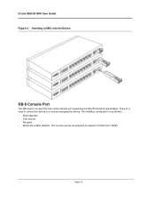
Page 12 The port is 9600 (default). The console can be reconfigured for speeds of 57600 and 115200. This interface configuration is as follows: • Eight data bits. • One stop bit. • No parity. • Baud rate is used to connect the device to a console managing the device. D-Link DES-3010PA User Guide Figure 3: Inserting a GBIC into the Device DB-9 Console Port The DB-9 port is an asynchronous serial console port supporting the RS-232 electrical specification.
Page 12 The port is 9600 (default). The console can be reconfigured for speeds of 57600 and 115200. This interface configuration is as follows: • Eight data bits. • One stop bit. • No parity. • Baud rate is used to connect the device to a console managing the device. D-Link DES-3010PA User Guide Figure 3: Inserting a GBIC into the Device DB-9 Console Port The DB-9 port is an asynchronous serial console port supporting the RS-232 electrical specification.
Product Manual
Page 14
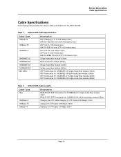
Device Description Cable Specifications Cable Specifications The following table contains the various cable specification for the DES-3010PA: Table 1: DES-3010PA Cable Specifications Cable Type 10Base-TX 100Base-TX 1000Base-T 1000BASE-LX 1000BASE-SX 1000BASE-LH 1000BASE-ZX Mini-GBIC Description ...Transceiver for 1000BASE-LH Single-mode fiber module (40km) SFP Transceiver for 1000BASE-ZX Single-mode fiber module (80km) : Table 2: DES-3010PA Cable Lengths Cable Type Fiber 1000Base-T 100Base-TX 10Base-TX Description DEM-310GT: SFP Transceiver for 1000BASE-LX, Single-mode fiber module 10km...
Device Description Cable Specifications Cable Specifications The following table contains the various cable specification for the DES-3010PA: Table 1: DES-3010PA Cable Specifications Cable Type 10Base-TX 100Base-TX 1000Base-T 1000BASE-LX 1000BASE-SX 1000BASE-LH 1000BASE-ZX Mini-GBIC Description ...Transceiver for 1000BASE-LH Single-mode fiber module (40km) SFP Transceiver for 1000BASE-ZX Single-mode fiber module (80km) : Table 2: DES-3010PA Cable Lengths Cable Type Fiber 1000Base-T 100Base-TX 10Base-TX Description DEM-310GT: SFP Transceiver for 1000BASE-LX, Single-mode fiber module 10km...
Product Manual
Page 15
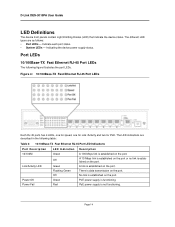
D-Link DES-3010PA User Guide LED Definitions The device front panels contain Light Emitting Diodes (LED) that ... Port LEDs Each RJ-45 ports has 4 LEDs, one for speed, one for Link /Activity and two for PoE. No link is established on the port. A link is data transmission on the port. Page 14 There is established on the port. PoE...LED Indication Green Off Green Flashing Green Off Green Red Description A 100 Mbps link is established on the port. A 10 Mbps link is established on the port or no link is established on the port. PoE power supply is not functioning. The LED...
D-Link DES-3010PA User Guide LED Definitions The device front panels contain Light Emitting Diodes (LED) that ... Port LEDs Each RJ-45 ports has 4 LEDs, one for speed, one for Link /Activity and two for PoE. No link is established on the port. A link is data transmission on the port. Page 14 There is established on the port. PoE...LED Indication Green Off Green Flashing Green Off Green Red Description A 100 Mbps link is established on the port. A 10 Mbps link is established on the port or no link is established on the port. PoE power supply is not functioning. The LED...
Product Manual
Page 17
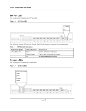
D-Link DES-3010PA User Guide SFP Port LEDs The following figure illustrates the system LEDs. Figure 7: System LEDs Page 16 No link is established on the port. System LEDs The following figure illustrates the SFP port LED. The LED indications are described in the following table: Table 5: SFP Port LED Indications Port Description Link/Activity LED LED Indication Green Flashing Green Off Description A link is data transmission on the port. Figure 6: SFP Port LED The SFP ports has one LEDs for Link / Activity. There is established on the port.
D-Link DES-3010PA User Guide SFP Port LEDs The following figure illustrates the system LEDs. Figure 7: System LEDs Page 16 No link is established on the port. System LEDs The following figure illustrates the SFP port LED. The LED indications are described in the following table: Table 5: SFP Port LED Indications Port Description Link/Activity LED LED Indication Green Flashing Green Off Description A link is data transmission on the port. Figure 6: SFP Port LED The SFP ports has one LEDs for Link / Activity. There is established on the port.
Product Manual
Page 19
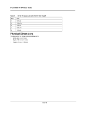
D-Link DES-3010PA User Guide Table 7: RJ-45 Pin Connections for 10/100/1000 Base-T Pin Use 4 TxRx 2- 5 TxRx 3+ 6 TxRx 3- 7 TxRx 4+ 8 TxRx 4- Physical Dimensions The device has the following physical dimensions: • Width: 280 mm (11 inch) • Depth: 180 mm (7.1 inch) • Height: 45 mm (1.75 inch) Page 18
D-Link DES-3010PA User Guide Table 7: RJ-45 Pin Connections for 10/100/1000 Base-T Pin Use 4 TxRx 2- 5 TxRx 3+ 6 TxRx 3- 7 TxRx 4+ 8 TxRx 4- Physical Dimensions The device has the following physical dimensions: • Width: 280 mm (11 inch) • Depth: 180 mm (7.1 inch) • Height: 45 mm (1.75 inch) Page 18

Product Manual
Page 21
... non-condensing. These components are to be adequately secured to cool before removing covers or touching internal equipment. • Ensure the switch does not overload the power circuits, wiring, and over . • Ensure the power source circuits are properly grounded. • ...Observe and follow service markings. Opening or removing covers marked with the rating limit for the circuit. DLINK DES-3010PA User Guide Preparing for Installation This section provides an explanation for preparing the installation site, and includes the following site requirements. &#...
... non-condensing. These components are to be adequately secured to cool before removing covers or touching internal equipment. • Ensure the switch does not overload the power circuits, wiring, and over . • Ensure the power source circuits are properly grounded. • ...Observe and follow service markings. Opening or removing covers marked with the rating limit for the circuit. DLINK DES-3010PA User Guide Preparing for Installation This section provides an explanation for preparing the installation site, and includes the following site requirements. &#...
Product Manual
Page 23
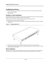
... rack, which can be installed on a flat surface or mounted in a wiring closet with the device should first be attached. DLINK DES-3010PA User Guide Installing the Device The device can be placed in a rack. This section includes the following topics: • Desktop or Shelf... Installation • Rack Installation Desktop or Shelf Installation When installing the switch on a desktop or shelf, the rubber feet included with other equipment. Attach these cushioning feet on the device. To install the device ...
... rack, which can be installed on a flat surface or mounted in a wiring closet with the device should first be attached. DLINK DES-3010PA User Guide Installing the Device The device can be placed in a rack. This section includes the following topics: • Desktop or Shelf... Installation • Rack Installation Desktop or Shelf Installation When installing the switch on a desktop or shelf, the rubber feet included with other equipment. Attach these cushioning feet on the device. To install the device ...

Product Manual
Page 25
Ensure that the weight of screws. This ensures that the ventilation holes are not obstructed. DLINK DES-3010PA User Guide Figure 11: Mounting Device in a Rack 5. Secure the unit to the rack with the rack screws (not provided). Page 24 Fasten the lower pair of screws before the upper pair of the unit is evenly distributed during installation.
Ensure that the weight of screws. This ensures that the ventilation holes are not obstructed. DLINK DES-3010PA User Guide Figure 11: Mounting Device in a Rack 5. Secure the unit to the rack with the rack screws (not provided). Page 24 Fasten the lower pair of screws before the upper pair of the unit is evenly distributed during installation.
Product Manual
Page 27
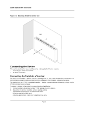
...no parity. c) Set the data format to the device Console port, perform the following sections: • Connecting the Switch to a Terminal • AC Power Connection Connecting the Switch to a Terminal The device is set as follows: a) Select the appropriate port to connect to 9600 baud. Ensure ...emulation software. 2. Connect a cable to the terminal running a terminal emulation software for monitoring and configuring the device. Page 26 DLINK DES-3010PA User Guide Figure 13: Mounting the device on the wall Connecting the Device This section describes how to connect the device, and ...
...no parity. c) Set the data format to the device Console port, perform the following sections: • Connecting the Switch to a Terminal • AC Power Connection Connecting the Switch to a Terminal The device is set as follows: a) Select the appropriate port to connect to 9600 baud. Ensure ...emulation software. 2. Connect a cable to the terminal running a terminal emulation software for monitoring and configuring the device. Page 26 DLINK DES-3010PA User Guide Figure 13: Mounting the device on the wall Connecting the Device This section describes how to connect the device, and ...

Product Manual
Page 29
D-Link DES-3010PA User Guide Section 3. Starting and Configuring the Device This section describes initial device configuration and includes the following topics: • Configuring the Terminal • Installation Procedure • Booting the Device • Configuration Overview • Advanced Configuration • Startup Procedures Page 28
D-Link DES-3010PA User Guide Section 3. Starting and Configuring the Device This section describes initial device configuration and includes the following topics: • Configuring the Terminal • Installation Procedure • Booting the Device • Configuration Overview • Advanced Configuration • Startup Procedures Page 28

Product Manual
Page 31
... within the first two seconds after the auto-boot message is blank. During boot, the Startup menu can be used to abort and enter prom. D-Link DES-3010PA User Guide Booting the Device The assumed bootup information is as follows: • The device is delivered with a default configuration. • The default user name...
... within the first two seconds after the auto-boot message is blank. During boot, the Startup menu can be used to abort and enter prom. D-Link DES-3010PA User Guide Booting the Device The assumed bootup information is as follows: • The device is delivered with a default configuration. • The default user name...
Product Manual
Page 33
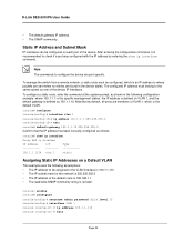
D-Link DES-3010PA User Guide • The default gateway IP address. • The SNMP community. Note The commands to check if a port was configured with the IP address ... admin password dlink level 15 console(config)# interface VLAN 1 console (config-if) # ip address 100.1.1.110 console (config-if) # exit Page 32 To manage the switch from a remote network, a static route must belong to the same subnet as one of the default route is 192.168.1.1 • The read/write SNMP...
D-Link DES-3010PA User Guide • The default gateway IP address. • The SNMP community. Note The commands to check if a port was configured with the IP address ... admin password dlink level 15 console(config)# interface VLAN 1 console (config-if) # ip address 100.1.1.110 console (config-if) # exit Page 32 To manage the switch from a remote network, a static route must belong to the same subnet as one of the default route is 192.168.1.1 • The read/write SNMP...


