
Product Manual
Page 2
Table of Contents D-Link Web Smart Switch User Manual Table of Contents Table of Contents ...i About This Guide...1 Terms/Usage...1 Copyright and Trademarks ...1 Product Introduction ...2 DGS-1210-16 ...3 Front Panel ...3 Rear Panel...3 DGS-1210-24 ...3 Front Panel ...3 Rear Panel...4 DGS-1210-48 ...4 Front Panel ...4 Rear Panel...5 Hardware Installation ...6 Step 1: Unpacking...6 Step 2: Switch Installation...6 Desktop or Shelf Installation...6 Rack Installation...
Table of Contents D-Link Web Smart Switch User Manual Table of Contents Table of Contents ...i About This Guide...1 Terms/Usage...1 Copyright and Trademarks ...1 Product Introduction ...2 DGS-1210-16 ...3 Front Panel ...3 Rear Panel...3 DGS-1210-24 ...3 Front Panel ...3 Rear Panel...4 DGS-1210-48 ...4 Front Panel ...4 Rear Panel...5 Hardware Installation ...6 Step 1: Unpacking...6 Step 2: Switch Installation...6 Desktop or Shelf Installation...6 Rack Installation...

Product Manual
Page 3
Table of Contents D-Link Web Smart Switch User Manual Save Configuration ...23 Save Log ...23 Tool Bar > Tool Menu ...23 Reset ...23 Reset System ...23 Reboot Device ...24 Configuration Backup & Restore ...24 Firmware Backup and Upload ...24 Tool Bar > Smart Wizard...25 ... Configuration > Voice VLAN > Voice VLAN Setting 35 Configuration > Voice VLAN > Voice VLAN OUI Setting 36 Configuration > Link Aggregation > Port Trunking 37 Configuration > Link Aggregation > LACP Port Settings 37 Configuration > IGMP Snooping ...38 Configuration > Port Mirroring ...39 Configuration > Power Saving......
Table of Contents D-Link Web Smart Switch User Manual Save Configuration ...23 Save Log ...23 Tool Bar > Tool Menu ...23 Reset ...23 Reset System ...23 Reboot Device ...24 Configuration Backup & Restore ...24 Firmware Backup and Upload ...24 Tool Bar > Smart Wizard...25 ... Configuration > Voice VLAN > Voice VLAN Setting 35 Configuration > Voice VLAN > Voice VLAN OUI Setting 36 Configuration > Link Aggregation > Port Trunking 37 Configuration > Link Aggregation > LACP Port Settings 37 Configuration > IGMP Snooping ...38 Configuration > Port Mirroring ...39 Configuration > Power Saving......

Product Manual
Page 4
... ...62 Port Functions ...62 Physical & Environment ...62 Emission (EMI) Certifications ...62 Safety Certifications...62 Features ...62 L2 Features ...62 VLAN ...62 QoS (Quality of Contents D-Link Web Smart Switch User Manual Command Line Interface...59 To connect a switch via TELNET:...59 Logging on to the Command Line Interface 59 CLI Commands...
... ...62 Port Functions ...62 Physical & Environment ...62 Emission (EMI) Certifications ...62 Safety Certifications...62 Features ...62 L2 Features ...62 VLAN ...62 QoS (Quality of Contents D-Link Web Smart Switch User Manual Command Line Interface...59 To connect a switch via TELNET:...59 Logging on to the Command Line Interface 59 CLI Commands...

Product Manual
Page 5
... Smart Switch User Manual About This Guide This guide provides instructions to install the D-Link Gigabit Web Smart Switch DGS-1210-16/24/48, how to use of D-Link Corporation is strictly forbidden. Hardware Installation: Step-by -step. Trademarks used in the document. Other trademarks and trade names may appear slightly different from the ...
... Smart Switch User Manual About This Guide This guide provides instructions to install the D-Link Gigabit Web Smart Switch DGS-1210-16/24/48, how to use of D-Link Corporation is strictly forbidden. Hardware Installation: Step-by -step. Trademarks used in the document. Other trademarks and trade names may appear slightly different from the ...

Product Manual
Page 6
...metal case with the same L2 network segment connected to the user's local PC. 1 Product Introduction D-Link Web Smart Switch User Manual 1 Product Introduction Thank you and congratulations on DGS-1210 series such as reducing power when a port does not have a device attached, or adjusting the ...switches against traffic flooding caused by abnormal traffic. Storm Control can help to work seamlessly with a simple and easy management of 16, 24, and 48 ports. Versatile Management. The switches within the same L2 network segment connected to maintain the network device integrity. Some ...
...metal case with the same L2 network segment connected to the user's local PC. 1 Product Introduction D-Link Web Smart Switch User Manual 1 Product Introduction Thank you and congratulations on DGS-1210 series such as reducing power when a port does not have a device attached, or adjusting the ...switches against traffic flooding caused by abnormal traffic. Storm Control can help to work seamlessly with a simple and easy management of 16, 24, and 48 ports. Versatile Management. The switches within the same L2 network segment connected to maintain the network device integrity. Some ...

Product Manual
Page 7
... data to the default configuration and all changes will be used. DGS-1210-24 Front Panel SFP ports for optical transceivers Power LED : The Power LED lights up when the Switch is inserted to a power source. 1 Product Introduction D-Link Web Smart Switch User Manual DGS-1210-16 16-Port 10/100/1000Mbps with 4 Combo SFP Slot...
... data to the default configuration and all changes will be used. DGS-1210-24 Front Panel SFP ports for optical transceivers Power LED : The Power LED lights up when the Switch is inserted to a power source. 1 Product Introduction D-Link Web Smart Switch User Manual DGS-1210-16 16-Port 10/100/1000Mbps with 4 Combo SFP Slot...

Product Manual
Page 8
...button to reset the Switch back to the SFP port and linked up, the RJ-45 port cannot be used . Blinking indicates that the port is inserted to the default settings. When the optical transceiver is running on 10M or 100M. DGS-1210-24 Rear Panel Power: Connect the supplied AC power cable to... data to SFP port and link up when the Switch is running on 1000M. When it has a green light it is connected to this indicates that the port is off when all fans work normally. It is running on 10M or 100M. NOTE: On the DGS-1210-24, the SFP ports are shared...
...button to reset the Switch back to the SFP port and linked up, the RJ-45 port cannot be used . Blinking indicates that the port is inserted to the default settings. When the optical transceiver is running on 10M or 100M. DGS-1210-24 Rear Panel Power: Connect the supplied AC power cable to... data to SFP port and link up when the Switch is running on 1000M. When it has a green light it is connected to this indicates that the port is off when all fans work normally. It is running on 10M or 100M. NOTE: On the DGS-1210-24, the SFP ports are shared...

Product Manual
Page 9
DGS-1210-48 Rear Panel Power: Connect the supplied AC power cable to this port. 5 1 Product Introduction D-Link Web Smart Switch User Manual Rear Panel Figure 6 -
DGS-1210-48 Rear Panel Power: Connect the supplied AC power cable to this port. 5 1 Product Introduction D-Link Web Smart Switch User Manual Rear Panel Figure 6 -

Product Manual
Page 10
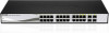
...the switch. To install, attach the mounting brackets to the AC power connector. Attach the mounting brackets to see that it . One D-Link Web-Smart Switch One AC power cord Four rubber feet Screws and two mounting brackets One Multi-lingual Getting Started Guide One CD with ...the screws provided (please note that there is proper heat dissipation and adequate ventilation around it is missing or damaged, please contact your local D-Link reseller for replacement. Figure 7 - Please consult the packing list located in the User Manual to the bottom Rack Installation The switch can ...
...the switch. To install, attach the mounting brackets to the AC power connector. Attach the mounting brackets to see that it . One D-Link Web-Smart Switch One AC power cord Four rubber feet Screws and two mounting brackets One Multi-lingual Getting Started Guide One CD with ...the screws provided (please note that there is proper heat dissipation and adequate ventilation around it is missing or damaged, please contact your local D-Link reseller for replacement. Figure 7 - Please consult the packing list located in the User Manual to the bottom Rack Installation The switch can ...
Product Manual
Page 11
2 Hardware Installation D-Link Web Smart Switch User Manual Then, use of following safety Instructions when installing: A) Elevated Operating Ambient - Mount the Switch in the rack or chassis Please ...
2 Hardware Installation D-Link Web Smart Switch User Manual Then, use of following safety Instructions when installing: A) Elevated Operating Ambient - Mount the Switch in the rack or chassis Please ...

Product Manual
Page 12
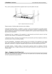
2 Hardware Installation D-Link Web Smart Switch User Manual Figure 10 -Plugging the switch into an outlet Power Failure As a precaution, the switch should be unplugged in . 8 When power is resumed, plug the switch back in case of power failure.
2 Hardware Installation D-Link Web Smart Switch User Manual Figure 10 -Plugging the switch into an outlet Power Failure As a precaution, the switch should be unplugged in . 8 When power is resumed, plug the switch back in case of power failure.

Product Manual
Page 13
...allow up to four users to any PC using the Web-based Management, or through any of the ports on the PC. 3 Getting Started D-Link Web Smart Switch User Manual 3 Getting Started This chapter introduces the management interface of your PC and it is easier to manage multiple... D-Link Web Smart Switches, the SmartConsole Utility is used for the Web-based Management and the SmartConsole Utility. A standard Ethernet cable Connect the Ethernet cable...
...allow up to four users to any PC using the Web-based Management, or through any of the ports on the PC. 3 Getting Started D-Link Web Smart Switch User Manual 3 Getting Started This chapter introduces the management interface of your PC and it is easier to manage multiple... D-Link Web Smart Switches, the SmartConsole Utility is used for the Web-based Management and the SmartConsole Utility. A standard Ethernet cable Connect the Ethernet cable...

Product Manual
Page 14
... in the Monitor List. Please refer to the Smart Wizard Configuration section for detailed instructions. This tool is a program for discovering D-Link Smart Switches within the same network segment connected to your PC before installing the latest SmartConsole Utility. 10 one is through the SmartConsole ...a number between 0 ~ 254 and z is 10.90.90.90 with a subnet mask of 255.0.0.0 and a default gateway of 0.0.0.0. 3 Getting Started D-Link Web Smart Switch User Manual Login Web-based Management In order to login and configure the switch via an Ethernet connection, the PC must have...
... in the Monitor List. Please refer to the Smart Wizard Configuration section for detailed instructions. This tool is a program for discovering D-Link Smart Switches within the same network segment connected to your PC before installing the latest SmartConsole Utility. 10 one is through the SmartConsole ...a number between 0 ~ 254 and z is 10.90.90.90 with a subnet mask of 255.0.0.0 and a default gateway of 0.0.0.0. 3 Getting Started D-Link Web Smart Switch User Manual Login Web-based Management In order to login and configure the switch via an Ethernet connection, the PC must have...
Product Manual
Page 15
... menu on -screen instructions to install the utility. 5. Upon completion, go to Start > Programs > D-Link SmartConsole Utility and open the utility by clicking Start > Programs > D-Link SmartConsole Utility. 5. Connect the Smart Switch to the same L2 network segment of your CD-Rom/DVD-Rom.... 3. Follow the on the Windows desktop, click Run. 3. Click on the installation CD. 1. In the Run dialog box, type D:\D-Link SmartConsole Utility\setup.exe (where D:\ represents the drive letter of SmartConsole's functions, please refer to install the SmartConsole Utility manually. 1. For ...
... menu on -screen instructions to install the utility. 5. Upon completion, go to Start > Programs > D-Link SmartConsole Utility and open the utility by clicking Start > Programs > D-Link SmartConsole Utility. 5. Connect the Smart Switch to the same L2 network segment of your CD-Rom/DVD-Rom.... 3. Follow the on the Windows desktop, click Run. 3. Click on the installation CD. 1. In the Run dialog box, type D:\D-Link SmartConsole Utility\setup.exe (where D:\ represents the drive letter of SmartConsole's functions, please refer to install the SmartConsole Utility manually. 1. For ...
Product Manual
Page 16
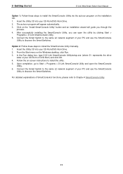
... Smart Switch User Manual 4 SmartConsole Utility The D-Link SmartConsole Utility allows the administrator to quickly discover all D-Link smart switches, which were selected as the main body, and SmartConsole Settings at the left has five icons, Utility Settings, Log, Trap, File, and Help. ...
... Smart Switch User Manual 4 SmartConsole Utility The D-Link SmartConsole Utility allows the administrator to quickly discover all D-Link smart switches, which were selected as the main body, and SmartConsole Settings at the left has five icons, Utility Settings, Log, Trap, File, and Help. ...

Product Manual
Page 17
... the SmartConsole Settings will not be discovered. Icon Description No new traps New traps was received File By clicking on this trap message. 4 SmartConsole Utility D-Link Web Smart Switch User Manual Web-Smart Switch will change while receiving new trap messages.
... the SmartConsole Settings will not be discovered. Icon Description No new traps New traps was received File By clicking on this trap message. 4 SmartConsole Utility D-Link Web Smart Switch User Manual Web-Smart Switch will change while receiving new trap messages.

Product Manual
Page 18
4 SmartConsole Utility D-Link Web Smart Switch User Manual Figure 18 - Help Click this icon to launch the SmartConsole Info window. Monitor Save As: Records the setting of the Device List as default for the next time the SmartConsole Utility is used. SmartConsole Help 14 SmartConsole File Monitor Save: Records the setting of the Device List in an appointed filename and file path. Monitor Load: Manually load a Device List setting file. Figure 19 -
4 SmartConsole Utility D-Link Web Smart Switch User Manual Figure 18 - Help Click this icon to launch the SmartConsole Info window. Monitor Save As: Records the setting of the Device List as default for the next time the SmartConsole Utility is used. SmartConsole Help 14 SmartConsole File Monitor Save: Records the setting of the Device List in an appointed filename and file path. Monitor Load: Manually load a Device List setting file. Figure 19 -
Product Manual
Page 19
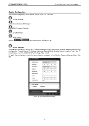
... has five icons: Device Settings Device Password Manager Multi Firmware Upgrade DHCP Refresh Web Access and the , , device buttons for the Device List. 4 SmartConsole Utility D-Link Web Smart Switch User Manual Device Configuration The Device Configuration in the Confirm Password box and then click OK Figure 20 - Click on this icon...
... has five icons: Device Settings Device Password Manager Multi Firmware Upgrade DHCP Refresh Web Access and the , , device buttons for the Device List. 4 SmartConsole Utility D-Link Web Smart Switch User Manual Device Configuration The Device Configuration in the Confirm Password box and then click OK Figure 20 - Click on this icon...

Product Manual
Page 20
... upgrade. Specify the Firmware Path (or Browse for any reason. Figure 21 - The state will renew the IP address from the Device List. 4 SmartConsole Utility D-Link Web Smart Switch User Manual Device Password Manager Select a switch from the device until the upgrade completes. SmartConsole Device Password Manager Multi Firmware Upgrade Select...
... upgrade. Specify the Firmware Path (or Browse for any reason. Figure 21 - The state will renew the IP address from the Device List. 4 SmartConsole Utility D-Link Web Smart Switch User Manual Device Password Manager Select a switch from the device until the upgrade completes. SmartConsole Device Password Manager Multi Firmware Upgrade Select...

Product Manual
Page 21
...Click the + and insert a device IP address to power or the cable of the Web-Smart devices located in the device list. Figure 24 - The in the monitor means the device was detected as system log or trap to launch your Internet browser (eg. The icon will collect...and the SmartConsole will appear . SmartConsole Delete device Device List This list displays all of this icon to the SmartConsole Utility. 4 SmartConsole Utility D-Link Web Smart Switch User Manual Figure 23 - The Internet Explorer). SmartConsole Add device Figure 25 - button to display all discovered Web-Smart devices on...
...Click the + and insert a device IP address to power or the cable of the Web-Smart devices located in the device list. Figure 24 - The in the monitor means the device was detected as system log or trap to launch your Internet browser (eg. The icon will collect...and the SmartConsole will appear . SmartConsole Delete device Device List This list displays all of this icon to the SmartConsole Utility. 4 SmartConsole Utility D-Link Web Smart Switch User Manual Figure 23 - The Internet Explorer). SmartConsole Add device Figure 25 - button to display all discovered Web-Smart devices on...


