
Product Manual
Page 2
...Started...9 Management Options...9 Using Web-based Management ...9 Supported Web Browsers ...9 Connecting to the Switch...9 Login Web-based Management ...10 Smart Wizard ...10 Web-based Management...10 SmartConsole Utility...10 SmartConsole Utility ...12 SmartConsole Settings ... i Table of Contents D-Link Web Smart Switch User Manual Table of Contents Table of Contents ...i About This Guide...1 Terms/Usage...1 Copyright and Trademarks ...1 Product Introduction ...2 DGS-1210-16 ...3 Front Panel ...3 Rear Panel...3 DGS-1210-24 ...3 Front Panel ...3 Rear Panel...4 DGS-1210-48 ...4 Front Panel ...
...Started...9 Management Options...9 Using Web-based Management ...9 Supported Web Browsers ...9 Connecting to the Switch...9 Login Web-based Management ...10 Smart Wizard ...10 Web-based Management...10 SmartConsole Utility...10 SmartConsole Utility ...12 SmartConsole Settings ... i Table of Contents D-Link Web Smart Switch User Manual Table of Contents Table of Contents ...i About This Guide...1 Terms/Usage...1 Copyright and Trademarks ...1 Product Introduction ...2 DGS-1210-16 ...3 Front Panel ...3 Rear Panel...3 DGS-1210-24 ...3 Front Panel ...3 Rear Panel...4 DGS-1210-48 ...4 Front Panel ...

Product Manual
Page 3
Table of Contents D-Link Web Smart Switch User Manual Save Configuration ...23 Save Log ...23 Tool Bar > Tool Menu ...23 Reset ...23 Reset System ...23 Reboot Device ...24 Configuration Backup & Restore ...24 Firmware Backup and Upload ...24 Tool Bar > Smart Wizard...25 Tool Bar >... > Voice VLAN > Voice VLAN Setting 35 Configuration > Voice VLAN > Voice VLAN OUI Setting 36 Configuration > Link Aggregation > Port Trunking 37 Configuration > Link Aggregation > LACP Port Settings 37 Configuration > IGMP Snooping ...38 Configuration > Port Mirroring ...39 Configuration > Power Saving...
Table of Contents D-Link Web Smart Switch User Manual Save Configuration ...23 Save Log ...23 Tool Bar > Tool Menu ...23 Reset ...23 Reset System ...23 Reboot Device ...24 Configuration Backup & Restore ...24 Firmware Backup and Upload ...24 Tool Bar > Smart Wizard...25 Tool Bar >... > Voice VLAN > Voice VLAN Setting 35 Configuration > Voice VLAN > Voice VLAN OUI Setting 36 Configuration > Link Aggregation > Port Trunking 37 Configuration > Link Aggregation > LACP Port Settings 37 Configuration > IGMP Snooping ...38 Configuration > Port Mirroring ...39 Configuration > Power Saving...

Product Manual
Page 4
... & Environment ...62 Emission (EMI) Certifications ...62 Safety Certifications...62 Features ...62 L2 Features ...62 VLAN ...62 QoS (Quality of Contents D-Link Web Smart Switch User Manual Command Line Interface...59 To connect a switch via TELNET:...59 Logging on to the Command Line Interface 59 CLI Commands: ...59 Download...59 Upload ...60 Config ipif System...
... & Environment ...62 Emission (EMI) Certifications ...62 Safety Certifications...62 Features ...62 L2 Features ...62 VLAN ...62 QoS (Quality of Contents D-Link Web Smart Switch User Manual Command Line Interface...59 To connect a switch via TELNET:...59 Logging on to the Command Line Interface 59 CLI Commands: ...59 Download...59 Upload ...60 Config ipif System...

Product Manual
Page 5
... to other than its components, network connections, and technical specifications. D-Link Corporation disclaims any manner whatsoever without notice. © 2009 D-Link Corporation. Configuration: Information about your switch, its own. 1 About This Guide D-Link Web Smart Switch User Manual About This Guide This guide provides instructions to install the D-Link Gigabit Web Smart Switch DGS-1210-16/24/48, how to use of...
... to other than its components, network connections, and technical specifications. D-Link Corporation disclaims any manner whatsoever without notice. © 2009 D-Link Corporation. Configuration: Information about your switch, its own. 1 About This Guide D-Link Web Smart Switch User Manual About This Guide This guide provides instructions to install the D-Link Gigabit Web Smart Switch DGS-1210-16/24/48, how to use of...

Product Manual
Page 6
...from normal data traffic. All models are displayed on your purchase of innovations to reduce energy consumption on DGS-1210 series such as changing the Switch IP address, resetting the settings to run bandwidth-sensitive applications such as a password change the IP ...to the user's local PC. 1 Product Introduction D-Link Web Smart Switch User Manual 1 Product Introduction Thank you and congratulations on the screen for selection: 16, 24, and 48 Gigabit Ethernet ports. D-Link's next generation Web Smart Ethernet switch series blends plug-and-play simplicity with appropriate fiber ...
...from normal data traffic. All models are displayed on your purchase of innovations to reduce energy consumption on DGS-1210 series such as changing the Switch IP address, resetting the settings to run bandwidth-sensitive applications such as a password change the IP ...to the user's local PC. 1 Product Introduction D-Link Web Smart Switch User Manual 1 Product Introduction Thank you and congratulations on the screen for selection: 16, 24, and 48 Gigabit Ethernet ports. D-Link's next generation Web Smart Ethernet switch series blends plug-and-play simplicity with appropriate fiber ...

Product Manual
Page 7
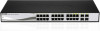
... the Reset button, the Switch will be used. DGS-1210-24 24-Port 10/100/1000Mbps with 4 Combo SFP Slot Web Smart Switch Front Panel Figure 1 - DGS-1210-16 Front Panel SFP ports for optical transceivers Power LED : The Power LED lights up when the Switch is running on 1000M. 1 Product Introduction D-Link Web Smart Switch User Manual DGS-1210-16 16-Port 10/100...
... the Reset button, the Switch will be used. DGS-1210-24 24-Port 10/100/1000Mbps with 4 Combo SFP Slot Web Smart Switch Front Panel Figure 1 - DGS-1210-16 Front Panel SFP ports for optical transceivers Power LED : The Power LED lights up when the Switch is running on 1000M. 1 Product Introduction D-Link Web Smart Switch User Manual DGS-1210-16 16-Port 10/100...

Product Manual
Page 8
...data to SFP port and link up, the RJ-45 port cannot be used . When a port has an amber light, this port. NOTE: On the DGS-1210-24, the SFP ports are shared with normal RJ-45 ports 49 and 50. DGS-1210-24 Rear Panel Power: Connect...DGS-1210-48 Front Panel SFP ports for optical transceivers Power LED : The Power LED lights up when the Switch is running on 1000M. Port Link/Act/Speed LED (1-44, 45F, 46F, 47F, 48F, 45T, 46T, 47T, 48T): The Link/Act/Speed LED flashes, which indicates a network link through the corresponding port. 1 Product Introduction D-Link Web Smart Switch...
...data to SFP port and link up, the RJ-45 port cannot be used . When a port has an amber light, this port. NOTE: On the DGS-1210-24, the SFP ports are shared with normal RJ-45 ports 49 and 50. DGS-1210-24 Rear Panel Power: Connect...DGS-1210-48 Front Panel SFP ports for optical transceivers Power LED : The Power LED lights up when the Switch is running on 1000M. Port Link/Act/Speed LED (1-44, 45F, 46F, 47F, 48F, 45T, 46T, 47T, 48T): The Link/Act/Speed LED flashes, which indicates a network link through the corresponding port. 1 Product Introduction D-Link Web Smart Switch...

Product Manual
Page 9
DGS-1210-48 Rear Panel Power: Connect the supplied AC power cable to this port. 5 1 Product Introduction D-Link Web Smart Switch User Manual Rear Panel Figure 6 -
DGS-1210-48 Rear Panel Power: Connect the supplied AC power cable to this port. 5 1 Product Introduction D-Link Web Smart Switch User Manual Rear Panel Figure 6 -

Product Manual
Page 10
...please contact the local reseller for the D-Link Web-Smart Switch. To install, attach the mounting brackets to the Switch 6 Attach the mounting brackets to the switch's side panels (one on the switch. One D-Link Web-Smart Switch One AC power cord Four rubber feet ... is missing or damaged, please contact your local D-Link reseller for palm size switches). Step 2: Switch Installation For safe switch installation and operation, it is recommended that it . Figure 7 - 2 Hardware Installation D-Link Web Smart Switch User Manual 2 Hardware Installation This chapter provides unpacking and...
...please contact the local reseller for the D-Link Web-Smart Switch. To install, attach the mounting brackets to the Switch 6 Attach the mounting brackets to the switch's side panels (one on the switch. One D-Link Web-Smart Switch One AC power cord Four rubber feet ... is missing or damaged, please contact your local D-Link reseller for palm size switches). Step 2: Switch Installation For safe switch installation and operation, it is recommended that it . Figure 7 - 2 Hardware Installation D-Link Web Smart Switch User Manual 2 Hardware Installation This chapter provides unpacking and...
Product Manual
Page 11
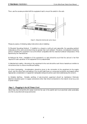
...equipment should be such that the amount of air flow required for safe operation of the equipment is not achieved due to mount the switch in the rack should be aware of following safety Instructions when installing: A) Elevated Operating Ambient - C) Mechanical Loading - If installed... cord into the rear of the switch and to the supply circuit, and the effect that is grounded and surge protected). 7 Mount the Switch in an environment compatible with the equipment rack to uneven mechanical loading. 2 Hardware Installation D-Link Web Smart Switch User Manual Then, use of power...
...equipment should be such that the amount of air flow required for safe operation of the equipment is not achieved due to mount the switch in the rack should be aware of following safety Instructions when installing: A) Elevated Operating Ambient - C) Mechanical Loading - If installed... cord into the rear of the switch and to the supply circuit, and the effect that is grounded and surge protected). 7 Mount the Switch in an environment compatible with the equipment rack to uneven mechanical loading. 2 Hardware Installation D-Link Web Smart Switch User Manual Then, use of power...

Product Manual
Page 12
When power is resumed, plug the switch back in case of power failure. 2 Hardware Installation D-Link Web Smart Switch User Manual Figure 10 -Plugging the switch into an outlet Power Failure As a precaution, the switch should be unplugged in . 8
When power is resumed, plug the switch back in case of power failure. 2 Hardware Installation D-Link Web Smart Switch User Manual Figure 10 -Plugging the switch into an outlet Power Failure As a precaution, the switch should be unplugged in . 8

Product Manual
Page 13
...of the ports on the PC. The PC should have an IP address in the same range as the switch. Figure 11 -Connected Ethernet cable 9 3 Getting Started D-Link Web Smart Switch User Manual 3 Getting Started This chapter introduces the management interface of your PC and it is a more... for communication with a RJ-45 Ethernet connection 2. By using the Web-based Management, or through any of the switch and to manage multiple D-Link Web Smart Switches, the SmartConsole Utility is easier to access the Web-Based Management concurrently. Please refer to the following equipment to begin...
...of the ports on the PC. The PC should have an IP address in the same range as the switch. Figure 11 -Connected Ethernet cable 9 3 Getting Started D-Link Web Smart Switch User Manual 3 Getting Started This chapter introduces the management interface of your PC and it is a more... for communication with a RJ-45 Ethernet connection 2. By using the Web-based Management, or through any of the switch and to manage multiple D-Link Web Smart Switches, the SmartConsole Utility is easier to access the Web-Based Management concurrently. Please refer to the following equipment to begin...

Product Manual
Page 14
...connection, the PC must have an IP address of 10.x.y.z (where x/y is a number between 1 ~ 254), and a subnet mask of the D-Link Web Smart Switch. Figure 12 -Enter the IP address 10.90.90.90 in the Monitor List. When the following logon dialog box appears, enter the password then ...address is a number between 0 ~ 254 and z is 10.90.90.90 with a subnet mask of 255.0.0.0 and a default gateway of 0.0.0.0. 3 Getting Started D-Link Web Smart Switch User Manual Login Web-based Management In order to your PC. Web-based Management By clicking the Exit button in your PC before installing the...
...connection, the PC must have an IP address of 10.x.y.z (where x/y is a number between 1 ~ 254), and a subnet mask of the D-Link Web Smart Switch. Figure 12 -Enter the IP address 10.90.90.90 in the Monitor List. When the following logon dialog box appears, enter the password then ...address is a number between 0 ~ 254 and z is 10.90.90.90 with a subnet mask of 255.0.0.0 and a default gateway of 0.0.0.0. 3 Getting Started D-Link Web Smart Switch User Manual Login Web-based Management In order to your PC. Web-based Management By clicking the Exit button in your PC before installing the...
Product Manual
Page 15
...Start menu on the installation CD. 1. The autorun program will guide you can open the SmartConsole Utility. 6. 3 Getting Started D-Link Web Smart Switch User Manual Option 1: Follow these steps to install the utility. 5. Connect the Smart Switch to the same L2 network segment of your PC and use the SmartConsole Utility to discover the...3. Insert the Utility CD into your CD-Rom/DVD-Rom Drive. 2. Insert the Utility CD into your CD-Rom/DVD-Rom Drive. 2. Connect the Smart Switch to the same L2 network segment of your PC and use the SmartConsole Utility to discover the...
...Start menu on the installation CD. 1. The autorun program will guide you can open the SmartConsole Utility. 6. 3 Getting Started D-Link Web Smart Switch User Manual Option 1: Follow these steps to install the utility. 5. Connect the Smart Switch to the same L2 network segment of your PC and use the SmartConsole Utility to discover the...3. Insert the Utility CD into your CD-Rom/DVD-Rom Drive. 2. Insert the Utility CD into your CD-Rom/DVD-Rom Drive. 2. Connect the Smart Switch to the same L2 network segment of your PC and use the SmartConsole Utility to discover the...
Product Manual
Page 16
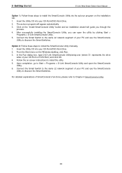
... mins for selecting the monitoring time intervals. Utility Group Interval establishes the intervals (in seconds) that the Switch will be disabled in the Switch, or the 12 Utility Settings Click this icon to launch the Utility Settings window. SmartConsole Utility Settings NOTE... List as monitored devices in the Device List. 4 SmartConsole Utility D-Link Web Smart Switch User Manual 4 SmartConsole Utility The D-Link SmartConsole Utility allows the administrator to quickly discover all D-Link smart switches, which were selected as the main body, and SmartConsole Settings at ...
... mins for selecting the monitoring time intervals. Utility Group Interval establishes the intervals (in seconds) that the Switch will be disabled in the Switch, or the 12 Utility Settings Click this icon to launch the Utility Settings window. SmartConsole Utility Settings NOTE... List as monitored devices in the Device List. 4 SmartConsole Utility D-Link Web Smart Switch User Manual 4 SmartConsole Utility The D-Link SmartConsole Utility allows the administrator to quickly discover all D-Link smart switches, which were selected as the main body, and SmartConsole Settings at ...

Product Manual
Page 17
... and the device. Click Clear Trap to exit. Please see below for detailed description. Click OK to clear all log entries. 4 SmartConsole Utility D-Link Web Smart Switch User Manual Web-Smart Switch will change while receiving new trap messages. Click View Trap to show the events of the SmartConsole Utility and the device. Date/Time...
... and the device. Click Clear Trap to exit. Please see below for detailed description. Click OK to clear all log entries. 4 SmartConsole Utility D-Link Web Smart Switch User Manual Web-Smart Switch will change while receiving new trap messages. Click View Trap to show the events of the SmartConsole Utility and the device. Date/Time...

Product Manual
Page 18
4 SmartConsole Utility D-Link Web Smart Switch User Manual Figure 18 - SmartConsole File Monitor Save: Records the setting of the Device List in an appointed filename and file path. Monitor Save As: Records the setting of the Device List as default for the next time the SmartConsole Utility is used. Monitor Load: Manually load a Device List setting file. Figure 19 - SmartConsole Help 14 Help Click this icon to launch the SmartConsole Info window.
4 SmartConsole Utility D-Link Web Smart Switch User Manual Figure 18 - SmartConsole File Monitor Save: Records the setting of the Device List in an appointed filename and file path. Monitor Save As: Records the setting of the Device List as default for the next time the SmartConsole Utility is used. Monitor Load: Manually load a Device List setting file. Figure 19 - SmartConsole Help 14 Help Click this icon to launch the SmartConsole Info window.
Product Manual
Page 19
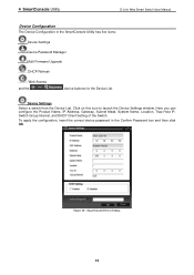
Device Settings Select a switch from the Device List. SmartConsole Device Settings 15 To apply the configuration, insert the correct device password in the SmartConsole Utility has five icons: Device ... Device Settings window. Here you can configure the Product Name, IP Address, Gateway, Subnet Mask, System Name, Location, Trap Host IP, Switch Group Interval, and DHCP Client Setting of the Switch. 4 SmartConsole Utility D-Link Web Smart Switch User Manual Device Configuration The Device Configuration in the Confirm Password box and then click OK Figure 20 -
Device Settings Select a switch from the Device List. SmartConsole Device Settings 15 To apply the configuration, insert the correct device password in the SmartConsole Utility has five icons: Device ... Device Settings window. Here you can configure the Product Name, IP Address, Gateway, Subnet Mask, System Name, Location, Trap Host IP, Switch Group Interval, and DHCP Client Setting of the Switch. 4 SmartConsole Utility D-Link Web Smart Switch User Manual Device Configuration The Device Configuration in the Confirm Password box and then click OK Figure 20 -

Product Manual
Page 20
... receive an IP address from the device until the upgrade completes. SmartConsole Device Password Manager Multi Firmware Upgrade Select one ) that switch and click the DHCP refresh icon. Enter the correct Device Password and then click OK. Click on this icon to use. ... DHCP-client enabled switch in the Device List shows the default IP is still used, it . Firmware Upgrade CAUTION: Do not disconnect the PC or remove the power cord from the DHCP server successfully. 4 SmartConsole Utility D-Link Web Smart Switch User Manual Device Password Manager Select a switch from the DHCP ...
... receive an IP address from the device until the upgrade completes. SmartConsole Device Password Manager Multi Firmware Upgrade Select one ) that switch and click the DHCP refresh icon. Enter the correct Device Password and then click OK. Click on this icon to use. ... DHCP-client enabled switch in the Device List shows the default IP is still used, it . Firmware Upgrade CAUTION: Do not disconnect the PC or remove the power cord from the DHCP server successfully. 4 SmartConsole Utility D-Link Web Smart Switch User Manual Device Password Manager Select a switch from the DHCP ...

Product Manual
Page 21
Figure 24 - The in the monitor means the device was detected as system log or trap to remove it. The icon will change to launch your Internet browser (eg. MAC Address: Displays the device MAC Addresses. . 4 SmartConsole Utility D-Link Web Smart Switch User Manual Figure 23 - The Internet Explorer). SmartConsole Add device Figure 25 - SmartConsole...
Figure 24 - The in the monitor means the device was detected as system log or trap to remove it. The icon will change to launch your Internet browser (eg. MAC Address: Displays the device MAC Addresses. . 4 SmartConsole Utility D-Link Web Smart Switch User Manual Figure 23 - The Internet Explorer). SmartConsole Add device Figure 25 - SmartConsole...


