
Reference Guide
Page 2
...Installation...6 Rack Installation ...6 Step 3 - Plugging in the AC Power Cord...7 Power Failure ...8 3 Getting Started...9 Management Options...9 Using Web-based Management ...9 Supported Web Browsers ...9 Connecting to the Switch...9 Login Web-based Management ...10 Smart Wizard ...10 Web-based Management...10 SmartConsole Utility...10 4 SmartConsole Utility ...12 SmartConsole Settings ...12 Utility Settings...12 Log...12 Trap ...13 File ...13 Help ...14 Device Configuration...14 Add(+), Delete(-) and Discover the device 16 Device List...16 5 Configuration ...18 Smart Wizard Configuration...
...Installation...6 Rack Installation ...6 Step 3 - Plugging in the AC Power Cord...7 Power Failure ...8 3 Getting Started...9 Management Options...9 Using Web-based Management ...9 Supported Web Browsers ...9 Connecting to the Switch...9 Login Web-based Management ...10 Smart Wizard ...10 Web-based Management...10 SmartConsole Utility...10 4 SmartConsole Utility ...12 SmartConsole Settings ...12 Utility Settings...12 Log...12 Trap ...13 File ...13 Help ...14 Device Configuration...14 Add(+), Delete(-) and Discover the device 16 Device List...16 5 Configuration ...18 Smart Wizard Configuration...

Reference Guide
Page 3
... D-Link Web Smart Switch User Manual SNMP ...19 Web-based Management...21 Tool Bar > Save Menu ...22 Save Configuration ...22 Save Log ...22 Tool Bar > Tool Menu ...22 Reset ...22 Reset System ...22 Reboot Device ...22 Configuration Backup and Restore ...23 Firmware Backup and Upgrade...23 Tool Bar > Smart Wizard...24 Tool Bar > Online Help...24 Function Tree ...26 Device Information...26 System > System Settings ...27 System > Password...27 System > Port Settings...27 System > DHCP Auto Configuration ...28 System > SysLog Host ...29 System > Time...
... D-Link Web Smart Switch User Manual SNMP ...19 Web-based Management...21 Tool Bar > Save Menu ...22 Save Configuration ...22 Save Log ...22 Tool Bar > Tool Menu ...22 Reset ...22 Reset System ...22 Reboot Device ...22 Configuration Backup and Restore ...23 Firmware Backup and Upgrade...23 Tool Bar > Smart Wizard...24 Tool Bar > Online Help...24 Function Tree ...26 Device Information...26 System > System Settings ...27 System > Password...27 System > Port Settings...27 System > DHCP Auto Configuration ...28 System > SysLog Host ...29 System > Time...
Reference Guide
Page 6
... configuration settings. All rights reserved. About This Guide D-Link Web Smart Switch User Manual About This Guide This guide provides instructions to install the D-Link Gigabit Web Smart Switch DGS-1210-20/28/28P/52, how to use of the device. Note: The model you have purchased may be used in the document. Smart Console Utility: An introduction to the Product Instruction and Technical Specification sections for basic switch installation and settings. 3. This guide is strictly forbidden. Some technologies refer to terms "switch", "bridge" and "switching hubs...
... configuration settings. All rights reserved. About This Guide D-Link Web Smart Switch User Manual About This Guide This guide provides instructions to install the D-Link Gigabit Web Smart Switch DGS-1210-20/28/28P/52, how to use of the device. Note: The model you have purchased may be used in the document. Smart Console Utility: An introduction to the Product Instruction and Technical Specification sections for basic switch installation and settings. 3. This guide is strictly forbidden. Some technologies refer to terms "switch", "bridge" and "switching hubs...
Reference Guide
Page 7
... changing the Switch IP address, resetting the settings to the port level. D-Link's innovative Safeguard Engine function protects the switches against traffic flooding caused by prioritizing that allows administrators to remotely control their network, using the Command Line Interface (CLI). 2 The switches within the same L2 network segment connected to the user's local PC. D-Link Green devices are displayed on DGS-1210 series such as server or gateway devices. The new generation of the smart switches. Besides, the series offers a PoE model with VLAN...
... changing the Switch IP address, resetting the settings to the port level. D-Link's innovative Safeguard Engine function protects the switches against traffic flooding caused by prioritizing that allows administrators to remotely control their network, using the Command Line Interface (CLI). 2 The switches within the same L2 network segment connected to the user's local PC. D-Link Green devices are displayed on DGS-1210 series such as server or gateway devices. The new generation of the smart switches. Besides, the series offers a PoE model with VLAN...

Reference Guide
Page 8
... data to connect the AC power cord. When it has a green light it is connected to a power source. Front Panel Figure 1.3 - Port Link/Act/Speed LED (1-24, 25F, 26F, 27F, 28F): The Link/Act/Speed LED flashes, which indicates a network link through the corresponding port. D-Link Web Smart Switches also come with D-View 6 SNMP Management Software, and provides easy-to the port. Front Panel Figure 1.1 - Reset: By pressing the Reset button for 5 seconds, the Switch will be lost. Rear Panel Figure 1.2 - DGS-1210-28 24-Port...
... data to connect the AC power cord. When it has a green light it is connected to a power source. Front Panel Figure 1.3 - Port Link/Act/Speed LED (1-24, 25F, 26F, 27F, 28F): The Link/Act/Speed LED flashes, which indicates a network link through the corresponding port. D-Link Web Smart Switches also come with D-View 6 SNMP Management Software, and provides easy-to the port. Front Panel Figure 1.1 - Reset: By pressing the Reset button for 5 seconds, the Switch will be lost. Rear Panel Figure 1.2 - DGS-1210-28 24-Port...

Reference Guide
Page 9
... D-Link Web Smart Switch User Manual Reset: Press the Reset button for IEEE802.3at compliance PDs. DGS-1210-28P 24-Port 10/100/1000Mbps plus 4 1000Base-T/SFP ports Web Smart PoE Switch. Front Panel Figure 1.5 - When the port LED glows in Link/Act mode, the port LEDs indicate a network link through the corresponding port. CAUTION: The MiniGBIC ports should use UL listed Optical Transceiver product, Rated Laser Class I . 3.3Vdc. Blinking indicates the Switch is connected to the outside plant. Rear Panel Figure 1.4 - Fan: The Fan LED lights green when fans work...
... D-Link Web Smart Switch User Manual Reset: Press the Reset button for IEEE802.3at compliance PDs. DGS-1210-28P 24-Port 10/100/1000Mbps plus 4 1000Base-T/SFP ports Web Smart PoE Switch. Front Panel Figure 1.5 - When the port LED glows in Link/Act mode, the port LEDs indicate a network link through the corresponding port. CAUTION: The MiniGBIC ports should use UL listed Optical Transceiver product, Rated Laser Class I . 3.3Vdc. Blinking indicates the Switch is connected to the outside plant. Rear Panel Figure 1.4 - Fan: The Fan LED lights green when fans work...

Reference Guide
Page 14
... own IP Address, which is used for the Web-based Management and the SmartConsole Utility. However, if you want to manage multiple D-Link Web Smart Switches, the SmartConsole Utility is easier to any port on the PC. A PC with the Web-Based Management or a SNMP network manager. Connected Ethernet cable 9 3 Getting Started D-Link Web Smart Switch User Manual 3 Getting Started This chapter introduces the management interface of your device: 1. Figure 3.1 - Management Options The D-Link Web Smart Switch can configure the Switch, monitor the network status, and display...
... own IP Address, which is used for the Web-based Management and the SmartConsole Utility. However, if you want to manage multiple D-Link Web Smart Switches, the SmartConsole Utility is easier to any port on the PC. A PC with the Web-Based Management or a SNMP network manager. Connected Ethernet cable 9 3 Getting Started D-Link Web Smart Switch User Manual 3 Getting Started This chapter introduces the management interface of your device: 1. Figure 3.1 - Management Options The D-Link Web Smart Switch can configure the Switch, monitor the network status, and display...

Reference Guide
Page 15
... two ways to login and configure the switch via an Ethernet connection, the PC must have an IP address of 10.x.y.z (where x/y is a number between 1 ~ 254), and a subnet mask of 255.0.0.0. 3 Getting Started D-Link Web Smart Switch User Manual Login Web-based Management In order to launch the Web-based Management, you through essential settings of the D-Link Web Smart Switch. For example, if the switch has an IP address of the Webbased Management interface then click OK...
... two ways to login and configure the switch via an Ethernet connection, the PC must have an IP address of 10.x.y.z (where x/y is a number between 1 ~ 254), and a subnet mask of 255.0.0.0. 3 Getting Started D-Link Web Smart Switch User Manual Login Web-based Management In order to launch the Web-based Management, you through essential settings of the D-Link Web Smart Switch. For example, if the switch has an IP address of the Webbased Management interface then click OK...
Reference Guide
Page 28
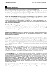
... backup settings file you can be uploaded to restore. Click Backup to save the current settings to be selected: HTTP or TFTP. Click Backup to save the current settings to a remote TFTP server. Tool Menu > Reboot Device Configuration Backup and Restore Allow the current configuration settings to your inventories for an existing firmware file to restore. Click Restore after restore, and all current configurations will be lost Firmware Backup and Upgrade Allow for the firmware to be saved, or for a saved backup settings file. 5 Configuration D-Link Web Smart Switch User Manual...
... backup settings file you can be uploaded to restore. Click Backup to save the current settings to be selected: HTTP or TFTP. Click Backup to save the current settings to a remote TFTP server. Tool Menu > Reboot Device Configuration Backup and Restore Allow the current configuration settings to your inventories for an existing firmware file to restore. Click Restore after restore, and all current configurations will be lost Firmware Backup and Upgrade Allow for the firmware to be saved, or for a saved backup settings file. 5 Configuration D-Link Web Smart Switch User Manual...

Reference Guide
Page 31
.... Default is disabled. Default is disabled. Port Mirroring: Click Settings to link to L2 Functions > Spanning Tree > STP Global Settings. Storm Control: Click Settings to link to System > DHCP Auto Configuration. DHCP Client: Click Settings to link to Security > Storm Control. The following sections provide more detailed description of the switch, including essential information such as firmware & hardware information, and IP address. Default is enabled. Jumbo Frame: Click Settings to link to System > Power Saving. Default is disabled. Default is disabled. 802.1X Status...
.... Default is disabled. Default is disabled. Port Mirroring: Click Settings to link to L2 Functions > Spanning Tree > STP Global Settings. Storm Control: Click Settings to link to System > DHCP Auto Configuration. DHCP Client: Click Settings to link to Security > Storm Control. The following sections provide more detailed description of the switch, including essential information such as firmware & hardware information, and IP address. Default is enabled. Jumbo Frame: Click Settings to link to System > Power Saving. Default is disabled. Default is disabled. 802.1X Status...

Reference Guide
Page 33
5 Configuration D-Link Web Smart Switch User Manual Figure 5.21 - Flow Control: You can be set as an MDI port in order to connect to enable the DHCP Auto Configuration feature on the switch to detect if the connection is designed on the Switch. Ports configured for users. The default setting is "Auto" MDI/MDIX. Switches and hubs usually use straight through Ethernet cables to adjust port speed settings appropriately after changing the connected cable media types. When connecting the Switch to properly match the connection. Auto MDI/MDIX is backwards, and automatically...
5 Configuration D-Link Web Smart Switch User Manual Figure 5.21 - Flow Control: You can be set as an MDI port in order to connect to enable the DHCP Auto Configuration feature on the switch to detect if the connection is designed on the Switch. Ports configured for users. The default setting is "Auto" MDI/MDIX. Switches and hubs usually use straight through Ethernet cables to adjust port speed settings appropriately after changing the connected cable media types. When connecting the Switch to properly match the connection. Auto MDI/MDIX is backwards, and automatically...

Reference Guide
Page 40
... 5.34 - This enables network managers to refresh the Auto Surveillance VLAN summary table. Default is 5. There are as follows: TX (transmit) mode: Duplicates the data transmitted from one port of up to be the static member port of the traffic in the Auto Surveillance VLAN. 5 Configuration D-Link Web Smart Switch User Manual VLAN page. Figure 5.35 - Tagged Uplink/Downlink Port: Specifies the ports to include all the Auto Surveillance VLAN rules. Description: Here to turn on the jumbo frame support. System will...
... 5.34 - This enables network managers to refresh the Auto Surveillance VLAN summary table. Default is 5. There are as follows: TX (transmit) mode: Duplicates the data transmitted from one port of up to be the static member port of the traffic in the Auto Surveillance VLAN. 5 Configuration D-Link Web Smart Switch User Manual VLAN page. Figure 5.35 - Tagged Uplink/Downlink Port: Specifies the ports to include all the Auto Surveillance VLAN rules. Description: Here to turn on the jumbo frame support. System will...

Reference Guide
Page 41
... an uplink port (for recovery when a Loopback is detected. By default, this function using the pull-down menu to a DHCP Server or Gateway). 5 Configuration D-Link Web Smart Switch User Manual RX (receive) mode: Duplicates the data that is received from the source port and forwards it to include all ports into port mirroring. To Port: The ending of a consecutive group of the port. Click Apply to detect the loop created by a specific port while Spanning Tree Protocol (STP) is not enabled...
... an uplink port (for recovery when a Loopback is detected. By default, this function using the pull-down menu to a DHCP Server or Gateway). 5 Configuration D-Link Web Smart Switch User Manual RX (receive) mode: Duplicates the data that is received from the source port and forwards it to include all ports into port mirroring. To Port: The ending of a consecutive group of the port. Click Apply to detect the loop created by a specific port while Spanning Tree Protocol (STP) is not enabled...

Reference Guide
Page 45
... field values are designated as passive cannot initially send LACP control frames. This allows LACP compliant devices to connections that are : Short (3 Sec) - Long (90 Sec) - Click Apply to create port trunking groups on the LAN. 5 Configuration D-Link Web Smart Switch User Manual Figure 5.41 - L2 Functions > Multicast > IGMP Snooping With Internet Group Management Protocol (IGMP) snooping, the Web Smart Switch can help reduce cluttered traffic on the Switch. Both devices must designate LACP ports as needs require.
... field values are designated as passive cannot initially send LACP control frames. This allows LACP compliant devices to connections that are : Short (3 Sec) - Long (90 Sec) - Click Apply to create port trunking groups on the LAN. 5 Configuration D-Link Web Smart Switch User Manual Figure 5.41 - L2 Functions > Multicast > IGMP Snooping With Internet Group Management Protocol (IGMP) snooping, the Web Smart Switch can help reduce cluttered traffic on the Switch. Both devices must designate LACP ports as needs require.

Reference Guide
Page 46
.... Default value is disabled. This timer will be purged from host is received over that there are no more members. This value may need to be entered: Host Timeout (130-153025 sec): This is the interval after which a learned host port entry will be purged. To enable IGMP snooping for controlling the frequency of IGMP traffic on a subnet. 5 Configuration D-Link Web Smart Switch User Manual The settings...
.... Default value is disabled. This timer will be purged from host is received over that there are no more members. This value may need to be entered: Host Timeout (130-153025 sec): This is the interval after which a learned host port entry will be purged. To enable IGMP snooping for controlling the frequency of IGMP traffic on a subnet. 5 Configuration D-Link Web Smart Switch User Manual The settings...

Reference Guide
Page 71
... manually set the port power current limitation to be given to control the PoE functions of the switch. To protect the DGS-1210-28P and the connected devices, the power limit function will display the PoE status including, Port Enable, Power Limit, Power (W), Voltage (V), Current (mA), Classification, Port Status. Figure 5.87 - The Switch also works in pre-802.3at mode. please "Refresh" to enable the time-based PoE function on designated port(s). 5 Configuration D-Link Web Smart Switch User Manual Power Used: Displays the current used power of a port...
... manually set the port power current limitation to be given to control the PoE functions of the switch. To protect the DGS-1210-28P and the connected devices, the power limit function will display the PoE status including, Port Enable, Power Limit, Power (W), Voltage (V), Current (mA), Classification, Port Status. Figure 5.87 - The Switch also works in pre-802.3at mode. please "Refresh" to enable the time-based PoE function on designated port(s). 5 Configuration D-Link Web Smart Switch User Manual Power Used: Displays the current used power of a port...

Reference Guide
Page 72
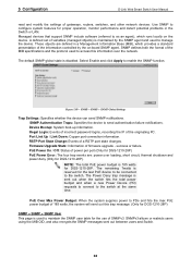
... same time. Port Link Up / Link Down: Copper port connection information. The Power Deny trap message is disabled. Figure 5.88 - SNMP enables network management stations to the managing station. "Auto" will be classified to non-AF PD or Legacy PD. PoE Power On / Off: Status of firmware upgrade - The remaining 7watts is overloaded. When the Trap Setting is enabled, enter the Destination IP address of the managing station that will send out this Web-Smart Switch...
... same time. Port Link Up / Link Down: Copper port connection information. The Power Deny trap message is disabled. Figure 5.88 - SNMP enables network management stations to the managing station. "Auto" will be classified to non-AF PD or Legacy PD. PoE Power On / Off: Status of firmware upgrade - The remaining 7watts is overloaded. When the Trap Setting is enabled, enter the Destination IP address of the managing station that will send out this Web-Smart Switch...
Reference Guide
Page 73
... controlled by the SNMP agent and used to the switch at the same time. Illegal Login: Events of incorrect password logins, recording the IP of a RSTP port state changes. 5 Configuration D-Link Web Smart Switch User Manual read and modify the settings of firmware upgrade - Use SNMP to manage the device. Managed devices that support SNMP include software (referred to as an agent), which provides a standard presentation of variables (managed objects) is used to configure system features for DGS-1210-28P). These objects are : power...
... controlled by the SNMP agent and used to the switch at the same time. Illegal Login: Events of incorrect password logins, recording the IP of a RSTP port state changes. 5 Configuration D-Link Web Smart Switch User Manual read and modify the settings of firmware upgrade - Use SNMP to manage the device. Managed devices that support SNMP include software (referred to as an agent), which provides a standard presentation of variables (managed objects) is used to configure system features for DGS-1210-28P). These objects are : power...

Reference Guide
Page 81
To connect a switch via TELNET protocol. To connect, launch any terminal software like HyperTerminal in both the Username and Password fields. Press Enter in Microsoft Windows, or just use the command prompt by typing the command telnet followed by using the Command Line Interface (CLI) via TELNET: 1. To change the login timeout session, please refer to log in the following table. download upload config ipif system logout ping reboot reset config show ipif show switch config account admin password save debug info { firmware_fromTFTP tftp://ip-address/filename | cfg_fromTFTP...
To connect a switch via TELNET protocol. To connect, launch any terminal software like HyperTerminal in both the Username and Password fields. Press Enter in Microsoft Windows, or just use the command prompt by typing the command telnet followed by using the Command Line Interface (CLI) via TELNET: 1. To change the login timeout session, please refer to log in the following table. download upload config ipif system logout ping reboot reset config show ipif show switch config account admin password save debug info { firmware_fromTFTP tftp://ip-address/filename | cfg_fromTFTP...
Reference Guide
Page 92
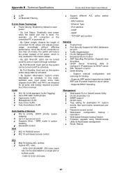
...UDP port number policy packet Security Trusted Host Port Security:Support 64 MAC addresses per port Supports Strict / WRR mode in queue handling Bandwidth Control AAA 802.1X RADIUS server 802.1X port-based access control Support different ACL contents: - ICMP - IPv4 address - Support manual configuration and scanning for destination IP, system events, fiber port events, twisted-pair port events Password access control Web-based configuration backup / restoration Web-based firmware backup/restore Firmware upgrade using SmartConsole Utility & Web-based management Reset, Reboot ACL...
...UDP port number policy packet Security Trusted Host Port Security:Support 64 MAC addresses per port Supports Strict / WRR mode in queue handling Bandwidth Control AAA 802.1X RADIUS server 802.1X port-based access control Support different ACL contents: - ICMP - IPv4 address - Support manual configuration and scanning for destination IP, system events, fiber port events, twisted-pair port events Password access control Web-based configuration backup / restoration Web-based firmware backup/restore Firmware upgrade using SmartConsole Utility & Web-based management Reset, Reboot ACL...


