Hardware Installation Guide
Page 3
DGS-3000 Series Layer 2 Managed Gigabit Switch Hardware Installation Guide Table of Contents Intended Readers ...v Typographical Conventions ...v Notes, Notices, and Cautions ...v Safety Instructions ...vi Safety Cautions ...vi General Precautions for Rack-Mountable Products ...vii Protecting Against Electrostatic Discharge...viii Chapter 1 Introduction...1 Switch Description ...1 Features ...1 Ports...3 Front Panel Components ...3 LED Indicators ...5 Rear Panel Description ...6 Side Panel Description ...7 Chapter 2 Installation...8 Package Contents...8 Installation Guidelines...8 Installing ...
DGS-3000 Series Layer 2 Managed Gigabit Switch Hardware Installation Guide Table of Contents Intended Readers ...v Typographical Conventions ...v Notes, Notices, and Cautions ...v Safety Instructions ...vi Safety Cautions ...vi General Precautions for Rack-Mountable Products ...vii Protecting Against Electrostatic Discharge...viii Chapter 1 Introduction...1 Switch Description ...1 Features ...1 Ports...3 Front Panel Components ...3 LED Indicators ...5 Rear Panel Description ...6 Side Panel Description ...7 Chapter 2 Installation...8 Package Contents...8 Installation Guidelines...8 Installing ...

Hardware Installation Guide
Page 4
DGS-3000 Series Layer 2 Managed Gigabit Switch Hardware Installation Guide Web Pages ...31 Appendix Section ...32 Appendix A - Technical Specifications...32 General ...32 Physical and Environmental ...32 Performance ...33 LED Indicators ...33 Port Functions...35 Appendix B - Cables and Connectors...37 Ethernet Cable...37 Console Cable ...38 Redundant Power Supply (RPS) Cable ...39 Warranties & Technical Support Information ...40 iv
DGS-3000 Series Layer 2 Managed Gigabit Switch Hardware Installation Guide Web Pages ...31 Appendix Section ...32 Appendix A - Technical Specifications...32 General ...32 Physical and Environmental ...32 Performance ...33 LED Indicators ...33 Port Functions...35 Appendix B - Cables and Connectors...37 Ethernet Cable...37 Console Cable ...38 Redundant Power Supply (RPS) Cable ...39 Warranties & Technical Support Information ...40 iv

Hardware Installation Guide
Page 5
... intended for set up and management of data and tells how to as printed in the manual. Do not type the brackets. A CAUTION indicates a potential for emphasis. For example: Click Enter. Menu Name > Menu Option Indicates the menu structure. Used for property damage, personal injury, or death. DGS-3000 Series Layer 2 Managed Gigabit Switch Hardware Installation Guide Intended Readers Typographical Conventions Notes, Notices, and Cautions Safety Instructions General...
... intended for set up and management of data and tells how to as printed in the manual. Do not type the brackets. A CAUTION indicates a potential for emphasis. For example: Click Enter. Menu Name > Menu Option Indicates the menu structure. Used for property damage, personal injury, or death. DGS-3000 Series Layer 2 Managed Gigabit Switch Hardware Installation Guide Intended Readers Typographical Conventions Notes, Notices, and Cautions Safety Instructions General...
Hardware Installation Guide
Page 6
.... DGS-3000 Series Layer 2 Managed Gigabit Switch Hardware Installation Guide Safety Instructions Use the following safety guidelines to ensure your own personal safety and to help protect your system from radiators and heat sources. o Opening or removing covers that need to be rated for the product and for the extension cable or power strip. vi o Do not service any AC-powered option intended for your system, purchase a power cable that...
.... DGS-3000 Series Layer 2 Managed Gigabit Switch Hardware Installation Guide Safety Instructions Use the following safety guidelines to ensure your own personal safety and to help protect your system from radiators and heat sources. o Opening or removing covers that need to be rated for the product and for the extension cable or power strip. vi o Do not service any AC-powered option intended for your system, purchase a power cable that...

Hardware Installation Guide
Page 7
... if uncertain that the stabilizers are considered to tip over . DGS-3000 Series Layer 2 Managed Gigabit Switch Hardware Installation Guide • To help protect the system from the power supplies. o Move products with applicable local, regional or national codes and practices. Also, refer to the rack installation documentation accompanying the system and the rack for joined multiple racks before working on the rack, make sure that suitable grounding is provided to the...
... if uncertain that the stabilizers are considered to tip over . DGS-3000 Series Layer 2 Managed Gigabit Switch Hardware Installation Guide • To help protect the system from the power supplies. o Move products with applicable local, regional or national codes and practices. Also, refer to the rack installation documentation accompanying the system and the rack for joined multiple racks before working on the rack, make sure that suitable grounding is provided to the...

Hardware Installation Guide
Page 9
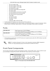
...; IEEE 802.1D Spanning Tree • IEEE 802.1w Rapid Spanning Tree • IEEE 802.1s Multiple Spanning Tree support • Jumbo frame to detect potential threats such as a 1U rackmount case suitable for metro and campus networks. The DGS-3000-10TC is part of the Layer 2 family of external sensors to 12K Bytes • Access Control List • ISM VLAN • DHCP local relay 1 The Series features the following list of numerous Gigabit connections.
...; IEEE 802.1D Spanning Tree • IEEE 802.1w Rapid Spanning Tree • IEEE 802.1s Multiple Spanning Tree support • Jumbo frame to detect potential threats such as a 1U rackmount case suitable for metro and campus networks. The DGS-3000-10TC is part of the Layer 2 family of external sensors to 12K Bytes • Access Control List • ISM VLAN • DHCP local relay 1 The Series features the following list of numerous Gigabit connections.
Hardware Installation Guide
Page 10
DGS-3000 Series Layer 2 Managed Gigabit Switch Hardware Installation Guide • Single IP Management • Access Authentication Control utilizing TACACS, XTACACS, TACACS+, and RADIUS protocols • Compound Authentication • Power saving mode • Simple Network Time Protocol (SNTP) • System Log • Full- Full duplex allows the switch port to 1.5 MByte • VLAN Trunking • Private VLAN • 802.1Q (2005 edition) • GVRP • Voice VLAN by MAC address • VLAN tagging based on PVID • IGMP Snooping v1, v2 and v3...
DGS-3000 Series Layer 2 Managed Gigabit Switch Hardware Installation Guide • Single IP Management • Access Authentication Control utilizing TACACS, XTACACS, TACACS+, and RADIUS protocols • Compound Authentication • Power saving mode • Simple Network Time Protocol (SNTP) • System Log • Full- Full duplex allows the switch port to 1.5 MByte • VLAN Trunking • Private VLAN • 802.1Q (2005 edition) • GVRP • Voice VLAN by MAC address • VLAN tagging based on PVID • IGMP Snooping v1, v2 and v3...
Hardware Installation Guide
Page 11
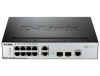
... Switch including SFP port LEDs. Twenty Copper ports (10/100/1000Mbps). Figure 1-1 Front panel view of LED indicators for Power, Console, RPS, Fan Err, and for Link/Act for port status such as link/act, speed, etc. • Web-based GUI compatible with a DB9 interface is provided to connect the Switch to a PC) NOTE: For customers interested in D-View, D-Link Corporation's proprietary SNMP management software, go to http://dview.dlink.com.tw/ and download the software and manual. Ports DGS-3000-10TC DGS-3000...
... Switch including SFP port LEDs. Twenty Copper ports (10/100/1000Mbps). Figure 1-1 Front panel view of LED indicators for Power, Console, RPS, Fan Err, and for Link/Act for port status such as link/act, speed, etc. • Web-based GUI compatible with a DB9 interface is provided to connect the Switch to a PC) NOTE: For customers interested in D-View, D-Link Corporation's proprietary SNMP management software, go to http://dview.dlink.com.tw/ and download the software and manual. Ports DGS-3000-10TC DGS-3000...

Hardware Installation Guide
Page 13
... LED blinks red when any of the device. DGS-3000 Series Layer 2 Managed Gigabit Switch Hardware Installation Guide LED Indicators The Switch front panel presents LED indicators for Power, Console, RPS, Fan Err, and Link/Act indicators for all fans are working normally. This LED lights green if the Redundant Power Supply (RPS) is connected, the RPS switch is no longer receiving power (i.e. The indicator is dark when the Switch is turned on to indicate the ready state of the fans has failed...
... LED blinks red when any of the device. DGS-3000 Series Layer 2 Managed Gigabit Switch Hardware Installation Guide LED Indicators The Switch front panel presents LED indicators for Power, Console, RPS, Fan Err, and Link/Act indicators for all fans are working normally. This LED lights green if the Redundant Power Supply (RPS) is connected, the RPS switch is no longer receiving power (i.e. The indicator is dark when the Switch is turned on to indicate the ready state of the fans has failed...
Hardware Installation Guide
Page 16
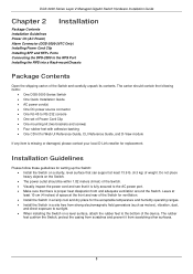
DGS-3000 Series Layer 2 Managed Gigabit Switch Hardware Installation Guide Chapter 2 Installation Package Contents Installation Guidelines Power On (AC Power) Alarm Connector (DGS-3000-26TC Only) Installing Power Cord Clip Installing SFP and SFP+ Ports Connecting the DPS-2000 to the RPS Port Installing the RPS into a Rack-mountChassis Package Contents Open the shipping carton of the Switch. • Visually inspect the power cord and see that it from strong electromagnetic field generators (such as motors), vibration, dust, and...
DGS-3000 Series Layer 2 Managed Gigabit Switch Hardware Installation Guide Chapter 2 Installation Package Contents Installation Guidelines Power On (AC Power) Alarm Connector (DGS-3000-26TC Only) Installing Power Cord Clip Installing SFP and SFP+ Ports Connecting the DPS-2000 to the RPS Port Installing the RPS into a Rack-mountChassis Package Contents Open the shipping carton of the Switch. • Visually inspect the power cord and see that it from strong electromagnetic field generators (such as motors), vibration, dust, and...
Hardware Installation Guide
Page 24
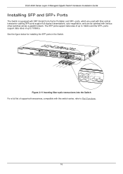
... For a full list of up to 1Gbit/s and the SFP+ ports support data rates of supported transceivers, compatible with various other switches across a gigabit network. The SFP ports support data rates of up to 10Gbit/s. DGS-3000 Series Layer 2 Managed Gigabit Switch Hardware Installation Guide Installing SFP and SFP+ Ports The Switch is equipped with SFP (Small Form Factor Portable) and SFP+ ports, which are used with fiber-optical transceiver cabling.SFP ports support full-duplex transmissions, auto-negotiation, and can be uplinked with this switch series, refer to Port Functions. 16
... For a full list of up to 1Gbit/s and the SFP+ ports support data rates of supported transceivers, compatible with various other switches across a gigabit network. The SFP ports support data rates of up to 10Gbit/s. DGS-3000 Series Layer 2 Managed Gigabit Switch Hardware Installation Guide Installing SFP and SFP+ Ports The Switch is equipped with SFP (Small Form Factor Portable) and SFP+ ports, which are used with fiber-optical transceiver cabling.SFP ports support full-duplex transmissions, auto-negotiation, and can be uplinked with this switch series, refer to Port Functions. 16
Hardware Installation Guide
Page 29
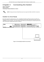
... Switch to Switch Connecting To Network Backbone or Server NOTE: All high-performance N-Way Ethernet ports can support both MDI-II and MDI-X connections. DGS-3000 Series Layer 2 Managed Gigabit Switch Hardware Installation Guide Chapter 3 Connecting the Switch Switch to End Node Switch to an end node 21 Connect the end node to the Switch via a twisted-pair UTP/STP cable. An end node connects to any of the 1000BASE-T ports of the Switch. The Link/Act LEDs for each Ethernet port will light green or amber...
... Switch to Switch Connecting To Network Backbone or Server NOTE: All high-performance N-Way Ethernet ports can support both MDI-II and MDI-X connections. DGS-3000 Series Layer 2 Managed Gigabit Switch Hardware Installation Guide Chapter 3 Connecting the Switch Switch to End Node Switch to an end node 21 Connect the end node to the Switch via a twisted-pair UTP/STP cable. An end node connects to any of the 1000BASE-T ports of the Switch. The Link/Act LEDs for each Ethernet port will light green or amber...

Hardware Installation Guide
Page 31
DGS-3000 Series Layer 2 Managed Gigabit Switch Hardware Installation Guide Connecting to Network Backbone or Server The combo SFP ports and the 1000BASE-T ports are made using a fiber-optic cable or Category 5e copper cable, depending on the type of 1000, 100 or 10Mbps in full duplex mode. Connections to the Gigabit Ethernet ports are ideal for uplinking to a server 23 The fiber-optic ports can operate at a speed of port. Figure 3-3 Connecting the Switch to a network backbone, server or server farm. A valid connection is indicated when the Link LED is lit...
DGS-3000 Series Layer 2 Managed Gigabit Switch Hardware Installation Guide Connecting to Network Backbone or Server The combo SFP ports and the 1000BASE-T ports are made using a fiber-optic cable or Category 5e copper cable, depending on the type of 1000, 100 or 10Mbps in full duplex mode. Connections to the Gigabit Ethernet ports are ideal for uplinking to a server 23 The fiber-optic ports can operate at a speed of port. Figure 3-3 Connecting the Switch to a network backbone, server or server farm. A valid connection is indicated when the Link LED is lit...

Hardware Installation Guide
Page 32
...and configuring the Switch. The Switch supports SNMP version 1.0, version 2.0 and version 3.0. SNMP-based Management The Switch can also connect a computer or terminal to the serial console port to access the Switch. To connect a terminal to the console port: Connect the male DB-9 connector on the console cable (shipped with the Switch. DGS-3000 Series Layer 2 Managed Gigabit Switch Hardware Installation Guide Chapter 4 Introduction to Switch Management Management Options Connecting the Console Port First Time Connecting to the Switch Password Protection IP Address Assignment SNMP Settings...
...and configuring the Switch. The Switch supports SNMP version 1.0, version 2.0 and version 3.0. SNMP-based Management The Switch can also connect a computer or terminal to the serial console port to access the Switch. To connect a terminal to the console port: Connect the male DB-9 connector on the console cable (shipped with the Switch. DGS-3000 Series Layer 2 Managed Gigabit Switch Hardware Installation Guide Chapter 4 Introduction to Switch Management Management Options Connecting the Console Port First Time Connecting to the Switch Password Protection IP Address Assignment SNMP Settings...
Hardware Installation Guide
Page 33
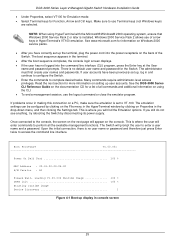
... disconnecting its power supply. If user accounts have correctly set to use Terminal keys (not Windows keys) are selected. Windows 2000 Service Pack 2 allows use the logout command or close the emulator program. The Switch will appear on the console. The boot sequence appears in HyperTerminal's VT100 emulation. This is installed. Many commands require administrator-level access privileges. DGS-3000 Series Layer 2 Managed Gigabit Switch Hardware Installation Guide • Under Properties, select VT100 for Emulation mode. • Select Terminal keys for more...
... disconnecting its power supply. If user accounts have correctly set to use Terminal keys (not Windows keys) are selected. Windows 2000 Service Pack 2 allows use the logout command or close the emulator program. The Switch will appear on the console. The boot sequence appears in HyperTerminal's VT100 emulation. This is installed. Many commands require administrator-level access privileges. DGS-3000 Series Layer 2 Managed Gigabit Switch Hardware Installation Guide • Under Properties, select VT100 for Emulation mode. • Select Terminal keys for more...
Hardware Installation Guide
Page 34
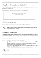
... a password. The Switch will be given to enter commands after the command prompt DGS-3000-26TC:admin# There is to create user accounts. Type the used for the Switch, do the following: 1. Upon initial connection to 15 characters in length. 26 At the CLI login prompt, enter create account admin followed by the Switch will verify the creation of unauthorized users from accessing the Switch or changing its settings. DGS-3000 Series Layer 2 Managed Gigabit Switch Hardware Installation Guide First Time Connecting to the Switch The Switch supports user...
... a password. The Switch will be given to enter commands after the command prompt DGS-3000-26TC:admin# There is to create user accounts. Type the used for the Switch, do the following: 1. Upon initial connection to 15 characters in length. 26 At the CLI login prompt, enter create account admin followed by the Switch will verify the creation of unauthorized users from accessing the Switch or changing its settings. DGS-3000 Series Layer 2 Managed Gigabit Switch Hardware Installation Guide First Time Connecting to the Switch The Switch supports user...

Hardware Installation Guide
Page 35
DGS-3000 Series Layer 2 Managed Gigabit Switch Hardware Installation Guide IP Address Assignment An IP address must be known. This MAC address cannot be changed, and can do as an SNMP manager. The Switch IP address can be automatically set using BOOTP or DHCP protocols, in the Device Information and System Information windows of variables (managed objects) is also assigned a unique MAC address by entering the command "show switch" into two parts. SNMP Settings Simple Network Management Protocol (SNMP) is 10.90.90.90. The...
DGS-3000 Series Layer 2 Managed Gigabit Switch Hardware Installation Guide IP Address Assignment An IP address must be known. This MAC address cannot be changed, and can do as an SNMP manager. The Switch IP address can be automatically set using BOOTP or DHCP protocols, in the Device Information and System Information windows of variables (managed objects) is also assigned a unique MAC address by entering the command "show switch" into two parts. SNMP Settings Simple Network Management Protocol (SNMP) is 10.90.90.90. The...
Hardware Installation Guide
Page 37
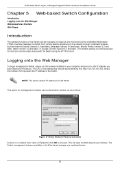
... browser installed on the network through a standard browser, such as seen below . 29 Manage the Switch from remote stations anywhere on your computer and point it to proceed. The browser acts as a universal access tool and can be managed, configured, and monitored via the embedded Web-based (HTML) interface. DGS-3000 Series Layer 2 Managed Gigabit Switch Hardware Installation Guide Chapter 5 Web-based Switch Configuration Introduction Logging onto the Web Manager Web-based User Interface Web Pages Introduction The software functions of the Switch.
... browser installed on the network through a standard browser, such as seen below . 29 Manage the Switch from remote stations anywhere on your computer and point it to proceed. The browser acts as a universal access tool and can be managed, configured, and monitored via the embedded Web-based (HTML) interface. DGS-3000 Series Layer 2 Managed Gigabit Switch Hardware Installation Guide Chapter 5 Web-based Switch Configuration Introduction Logging onto the Web Manager Web-based User Interface Web Pages Introduction The software functions of the Switch.

Hardware Installation Guide
Page 40
... the notch and turn the key to enhance the reliability. The lock-and-cable apparatus should be able to connect to be purchased separately. When internal power is failed, the optional external RPS will take over all the power immediately and automatically. DGS-3000 Series Layer 2 Managed Gigabit Switch Hardware Installation Guide Appendix Section Appendix A - Technical Specifications General Feature Standards Protocols Data Transfer Rates: Ethernet Fast Ethernet Gigabit Ethernet 10 Gigabit Ethernet Network Cables Number of the switch, to a secure immovable...
... the notch and turn the key to enhance the reliability. The lock-and-cable apparatus should be able to connect to be purchased separately. When internal power is failed, the optional external RPS will take over all the power immediately and automatically. DGS-3000 Series Layer 2 Managed Gigabit Switch Hardware Installation Guide Appendix Section Appendix A - Technical Specifications General Feature Standards Protocols Data Transfer Rates: Ethernet Fast Ethernet Gigabit Ethernet 10 Gigabit Ethernet Network Cables Number of the switch, to a secure immovable...

Hardware Installation Guide
Page 41
... port Supports 16K MAC addresses Full-wire speed (full-duplex) operation on . Power off . LED Indicators Location Per Device LED Indicative Power Console RPS Fan Err Color Green Green Green Red Status Solid Light Light off Solid Light Light off Solid Light Light off Blinking Light off . When any of the fans has failed. Console on . Manage up to 32 devices in a virtual stack with a single IP address. Console off . RPS is not connected or the RPS switch is turned on all fans work normally. 33 DGS-3000 Series Layer 2 Managed Gigabit Switch Hardware Installation Guide...
... port Supports 16K MAC addresses Full-wire speed (full-duplex) operation on . Power off . LED Indicators Location Per Device LED Indicative Power Console RPS Fan Err Color Green Green Green Red Status Solid Light Light off Solid Light Light off Solid Light Light off Blinking Light off . When any of the fans has failed. Console on . Manage up to 32 devices in a virtual stack with a single IP address. Console off . RPS is not connected or the RPS switch is turned on all fans work normally. 33 DGS-3000 Series Layer 2 Managed Gigabit Switch Hardware Installation Guide...


