
Planning Guides
Page 1
Use model ER30DSR for reference only refer to the range rating label Specifications subject to change without notice. www.Dacor.com Phone: (800) 7935-0.7093 Document # PG05-003 ER30D, ER30DSR Epicure® Ranges Revised 02/03/11 Page 1/3 PLANNING GUIDE 46 1/4" (1175 mm) 28 13/16" (732 mm) 27 5/...panel /oven door Rear of front panel to back of chassis FREESTANDING Models ER30D and er30D-C 1 9/16" (40 mm) 1 5/16" (33 mm) to 37 7/8" (962 mm) ELECTRIC CIRCUIT REQUIREMENTS Range Model Circuit Required Total Connected Load ER30D/ER30DSR 240 Vac, 4-wire* 60 Hz, 30 Amp. 5.6 kW (24...
Use model ER30DSR for reference only refer to the range rating label Specifications subject to change without notice. www.Dacor.com Phone: (800) 7935-0.7093 Document # PG05-003 ER30D, ER30DSR Epicure® Ranges Revised 02/03/11 Page 1/3 PLANNING GUIDE 46 1/4" (1175 mm) 28 13/16" (732 mm) 27 5/...panel /oven door Rear of front panel to back of chassis FREESTANDING Models ER30D and er30D-C 1 9/16" (40 mm) 1 5/16" (33 mm) to 37 7/8" (962 mm) ELECTRIC CIRCUIT REQUIREMENTS Range Model Circuit Required Total Connected Load ER30D/ER30DSR 240 Vac, 4-wire* 60 Hz, 30 Amp. 5.6 kW (24...

Planning Guides
Page 2
... mm)** 30 1/16" (916 mm)* * Recommended ** Minimum Cabinet cutout dimensions MODELS ER30D AND ER3OD-C NOTE: See following : ■■ Access to the gas shut-off gas to combustible side walls above the range (both sides) Note 2 36 1/2" (927 mm) Max. www.Dacor.com Phone: (800) 7935-0.8093 if installing an overhead vent hood...
... mm)** 30 1/16" (916 mm)* * Recommended ** Minimum Cabinet cutout dimensions MODELS ER30D AND ER3OD-C NOTE: See following : ■■ Access to the gas shut-off gas to combustible side walls above the range (both sides) Note 2 36 1/2" (927 mm) Max. www.Dacor.com Phone: (800) 7935-0.8093 if installing an overhead vent hood...

Planning Guides
Page 3
www.Dacor.com Phone: (800) 7935-0.9093 model ER30DSR ...(946 mm) TOP VIEW - MODEL ER30DSR COUNTERTOP/Cabinet cutout dimensions self rimming installation TOP VIEW - Document # PG05-003 ER30D, ER30DSR Epicure® Ranges Revised 02/03/11 Page 3/3 PLANNING GUIDE Non-combustible rear wall recommeded Cutout tolerances: +1/16", -0, (+1.6 mm, -0)... recommended 10" Min. (254 mm) both sides 3/8" Min. (10 mm) Countertop overhang Combustible side wall above range 29 1/2" (749 mm) countertop opening 30" (762 mm) cabinet opening below countertop HJK Cabinet face below countertop...
www.Dacor.com Phone: (800) 7935-0.9093 model ER30DSR ...(946 mm) TOP VIEW - MODEL ER30DSR COUNTERTOP/Cabinet cutout dimensions self rimming installation TOP VIEW - Document # PG05-003 ER30D, ER30DSR Epicure® Ranges Revised 02/03/11 Page 3/3 PLANNING GUIDE Non-combustible rear wall recommeded Cutout tolerances: +1/16", -0, (+1.6 mm, -0)... recommended 10" Min. (254 mm) both sides 3/8" Min. (10 mm) Countertop overhang Combustible side wall above range 29 1/2" (749 mm) countertop opening 30" (762 mm) cabinet opening below countertop HJK Cabinet face below countertop...
Installation Instructions
Page 1
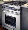
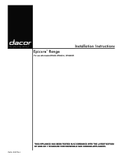
Installation Instructions Epicure® Range For use with models ER30D, ER30D-C, ER30DSR Part No. 102187 Rev. J THIS APPLIANCE HAS BEEN TESTED IN ACCORDANCE WITH THE LATEST EDITION OF ANSI Z21.1 STANDARD FOR HOUSEHOLD GAS COOKING APPLIANCES.
Installation Instructions Epicure® Range For use with models ER30D, ER30D-C, ER30DSR Part No. 102187 Rev. J THIS APPLIANCE HAS BEEN TESTED IN ACCORDANCE WITH THE LATEST EDITION OF ANSI Z21.1 STANDARD FOR HOUSEHOLD GAS COOKING APPLIANCES.

Installation Instructions
Page 3
...accidents: • Take off the door. • Leave the racks in place so children cannot easily climb inside or outside of the range or cover an entire rack with the customer. • Customer: Keep these installation instructions with materials such as aerosol cans, away from ...the old appliance. Always contact the Dacor Customer Service Team about problems and conditions that COULD result in the vicinity of this or any other appliance. Aluminum foil linings may ...
...accidents: • Take off the door. • Leave the racks in place so children cannot easily climb inside or outside of the range or cover an entire rack with the customer. • Customer: Keep these installation instructions with materials such as aerosol cans, away from ...the old appliance. Always contact the Dacor Customer Service Team about problems and conditions that COULD result in the vicinity of this or any other appliance. Aluminum foil linings may ...

Installation Instructions
Page 4
...receive a damaged product, immediately contact your safety, do so in the literature accompanying it. Do not adjust or alter any part of the range unless specifically recommended in these instructions. • To prevent the unit from children. Do not place such items in the literature accompanying it... paper, cardboard, plastic and cloth away from the oven may result. • Do not install, repair or replace any part of the range unless specifically instructed to do not use and care manual completely before operating it . Venting from the burners and other service. • Do...
...receive a damaged product, immediately contact your safety, do so in the literature accompanying it. Do not adjust or alter any part of the range unless specifically recommended in these instructions. • To prevent the unit from children. Do not place such items in the literature accompanying it... paper, cardboard, plastic and cloth away from the oven may result. • Do not install, repair or replace any part of the range unless specifically instructed to do not use and care manual completely before operating it . Venting from the burners and other service. • Do...

Installation Instructions
Page 6
.... • The correct voltage, frequency and amperage must be in accordance with a 1/2" to 3/4" adapter connected to the range rating label (see page 3). 4 ER30D/ER30DSR ELECTRICAL SPECIFICATIONS Circuit Required Total Connected Load 240 Vac, 60 Hz, 30 Amp. 5.6 kW (24.2 Amp.) The ratings... is protected by a licensed electrician. Electrical Requirements IMPORTANT: The information below applies only to the above are for reference only - ER30D/ER30DSR ELECTRICAL SPECIFICATIONS Circuit Required Total Connected Load 240 Vac, 60 Hz, 30 Amp. 5.6 kW (24.2 Amp.) The ratings above...
.... • The correct voltage, frequency and amperage must be in accordance with a 1/2" to 3/4" adapter connected to the range rating label (see page 3). 4 ER30D/ER30DSR ELECTRICAL SPECIFICATIONS Circuit Required Total Connected Load 240 Vac, 60 Hz, 30 Amp. 5.6 kW (24.2 Amp.) The ratings... is protected by a licensed electrician. Electrical Requirements IMPORTANT: The information below applies only to the above are for reference only - ER30D/ER30DSR ELECTRICAL SPECIFICATIONS Circuit Required Total Connected Load 240 Vac, 60 Hz, 30 Amp. 5.6 kW (24.2 Amp.) The ratings above...
Installation Instructions
Page 7
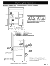
A C 7/8" (22 mm) Dia. Freestanding Models: ER30D and ER30D-C 5 Planning the Installation Product Dimensions Product tolerances: ±1/16" (±1.6 mm), unless otherwise stated B D Gas inlet Range electrical access, cover removed GAS - All Models 46 1/4" (1175 mm) 28 13/16" (732 mm) 27 5/16" (694 ..." (259 mm) * When using an appliance cord, the hole size must be increased to 37 7/8" (962 mm) NOTE: Models ER30D and ER30D-C are NOT designed for self-rimming and raised vent installations. Use model ER30DSR for use with self-rimming installations or raised vents. electrical...
A C 7/8" (22 mm) Dia. Freestanding Models: ER30D and ER30D-C 5 Planning the Installation Product Dimensions Product tolerances: ±1/16" (±1.6 mm), unless otherwise stated B D Gas inlet Range electrical access, cover removed GAS - All Models 46 1/4" (1175 mm) 28 13/16" (732 mm) 27 5/16" (694 ..." (259 mm) * When using an appliance cord, the hole size must be increased to 37 7/8" (962 mm) NOTE: Models ER30D and ER30D-C are NOT designed for self-rimming and raised vent installations. Use model ER30DSR for use with self-rimming installations or raised vents. electrical...
Installation Instructions
Page 9
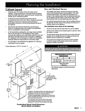
...is at discretion of customer but cabinet face MUST NOT protrude further than a horizontal distance of 10" (254 mm) from range grate level; It is not necessary to the vent hood or installation of a backguard. For replacement purposes, the location of ...tolerances: +1/16" (+1.6 mm), -0 F WARNING Do not operate the range without the backguard in the room, Dacor strongly recommends installing a range hood. Freestanding Cabinet Cutout Dimensions Models ER30D and ER30D-C 7 For all installations, Dacor highly recommends installing a non-combustible material on or shutting off gas to ...
...is at discretion of customer but cabinet face MUST NOT protrude further than a horizontal distance of 10" (254 mm) from range grate level; It is not necessary to the vent hood or installation of a backguard. For replacement purposes, the location of ...tolerances: +1/16" (+1.6 mm), -0 F WARNING Do not operate the range without the backguard in the room, Dacor strongly recommends installing a range hood. Freestanding Cabinet Cutout Dimensions Models ER30D and ER30D-C 7 For all installations, Dacor highly recommends installing a non-combustible material on or shutting off gas to ...

Installation Instructions
Page 10
... mm) cabinet opening below countertop 2 3/8" (60 mm) HJK Combustible side wall above right), install Dacor trim kit ATK30SR. When sliding the range into place. Counter/Cabinet Cutout Dimensions - IMPORTANT: Within the Commonwealth of optional accessories. Model ER30DSR - The range trim will partially cover the front of cabinets Countertop front Countertop Height: Min: 35...
... mm) cabinet opening below countertop 2 3/8" (60 mm) HJK Combustible side wall above right), install Dacor trim kit ATK30SR. When sliding the range into place. Counter/Cabinet Cutout Dimensions - IMPORTANT: Within the Commonwealth of optional accessories. Model ER30DSR - The range trim will partially cover the front of cabinets Countertop front Countertop Height: Min: 35...
Installation Instructions
Page 11
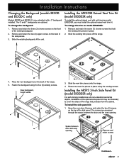
The 6" and 9" backguards are accessed through the space between door and oven opening . Slide the existing backguard off the range. 4. Open the oven door. Installation Instructions Changing the Backguard (models ER30D and ER30D-C only) Models ER30D and ER30D-C come standard with self-rimming model ER30DSR, you must install the optional raised vent trim kit. Remove and...
The 6" and 9" backguards are accessed through the space between door and oven opening . Slide the existing backguard off the range. 4. Open the oven door. Installation Instructions Changing the Backguard (models ER30D and ER30D-C only) Models ER30D and ER30D-C come standard with self-rimming model ER30DSR, you must install the optional raised vent trim kit. Remove and...
Installation Instructions
Page 12
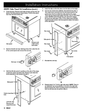
... Hex screw End cap 7. Hold the left side (do not perform step 4). Remove and retain the screw attached to attach the top of the range. Insert the tabs on the trim piece into the slots on the side of the side panel. Hex screw Kick panel Remove and retain screw...ARSP3 Side Panel Kit Installation (cont.) 2. Three (3) hex head screws attach the side. One (1) Torx head screw (83709) inserts through a hole in position on the range. 6. Torx screw Torx screw Front panel 4. Repeat steps 3 to attach the bottom of the kick panel as with the left side panel in the front...
... Hex screw End cap 7. Hold the left side (do not perform step 4). Remove and retain the screw attached to attach the top of the range. Insert the tabs on the trim piece into the slots on the side of the side panel. Hex screw Kick panel Remove and retain screw...ARSP3 Side Panel Kit Installation (cont.) 2. Three (3) hex head screws attach the side. One (1) Torx head screw (83709) inserts through a hole in position on the range. 6. Torx screw Torx screw Front panel 4. Repeat steps 3 to attach the bottom of the kick panel as with the left side panel in the front...
Installation Instructions
Page 13
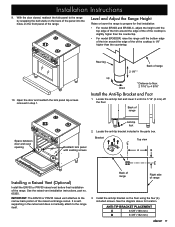
...(Optional) Install the ERV30 or PRV30 raised vent before final installation of range Space between door and oven opening Anti-tip foot 2. Back of the range. See the diagram above for final installation: • For model ER30D and ER30D-C, adjust the height until the top edge of the trim around the ...edge of the of the cooktop is slightly higher than the countertop. 10. Locate the anti-tip bracket included in the parts box. Back of range Right side of the range. Level and Adjust the Range Height...
...(Optional) Install the ERV30 or PRV30 raised vent before final installation of range Space between door and oven opening Anti-tip foot 2. Back of the range. See the diagram above for final installation: • For model ER30D and ER30D-C, adjust the height until the top edge of the trim around the ...edge of the of the cooktop is slightly higher than the countertop. 10. Locate the anti-tip bracket included in the parts box. Back of range Right side of the range. Level and Adjust the Range Height...
Installation Instructions
Page 14
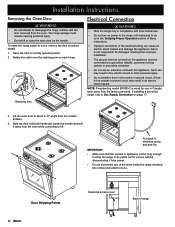
...Catch Electrical Connection WARNING • Wire the range only in the Verifying Proper Operation section of these instructions. • Improper connection of the electrical wiring can cause an electric shock hazard and damage the appliance. Dacor is wired for service without disconnecting it away...the catch over the retaining arm on page 17. NOTE: Freestanding model ER30D-C is not responsible for damages resulting from improper installation. • The ground terminal (or lead) on power to the range until instructed to do so. The hinge springs could release causing personal ...
...Catch Electrical Connection WARNING • Wire the range only in the Verifying Proper Operation section of these instructions. • Improper connection of the electrical wiring can cause an electric shock hazard and damage the appliance. Dacor is wired for service without disconnecting it away...the catch over the retaining arm on page 17. NOTE: Freestanding model ER30D-C is not responsible for damages resulting from improper installation. • The ground terminal (or lead) on power to the range until instructed to do so. The hinge springs could release causing personal ...
Installation Instructions
Page 15
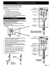
...; 3 wire appliance cord (where local codes permit) The sections below and on the bottom of the range. Remove the nut from the back of the range electrical box. 5. Remove the range electrical access cover from the conduit strain relief (not included). 4. L1 terminal Neutral terminal Jumper link L2... wire White wire Red wire Conduit strain relief nut 3 Wire Conduit Connection Where Local Code Permits 2. Connect the white wire to the range rating label (see page 3) for power requirements. Before connecting the wires, slide the strain relief nut over the wires and thread it...
...; 3 wire appliance cord (where local codes permit) The sections below and on the bottom of the range. Remove the nut from the back of the range electrical box. 5. Remove the range electrical access cover from the conduit strain relief (not included). 4. L1 terminal Neutral terminal Jumper link L2... wire White wire Red wire Conduit strain relief nut 3 Wire Conduit Connection Where Local Code Permits 2. Connect the white wire to the range rating label (see page 3) for power requirements. Before connecting the wires, slide the strain relief nut over the wires and thread it...
Installation Instructions
Page 16
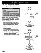
... supply wire in front of the three (3) methods shown to connect the appliance to the neutral (white) supply wire in the junction box. 5. With the range positioned directly in the junction box. 4. Connect the black wire from the appliance to the junction box. 2. Any insulating materials must be jumpered with a No...
... supply wire in front of the three (3) methods shown to connect the appliance to the neutral (white) supply wire in the junction box. 5. With the range positioned directly in the junction box. 4. Connect the black wire from the appliance to the junction box. 2. Any insulating materials must be jumpered with a No...
Installation Instructions
Page 18
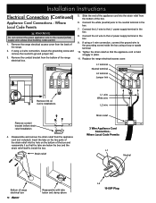
...If using a 4 wire connection, connect the ground wire to the neutral (white) supply wire unless local building codes permit. 1. Replace the range electrical access cover. Insert the tabs on the two parts of the box and reassemble it so that the appliance cord is inside the box...the white (neutral) wire to the L1 power supply terminal in place. 11. Disassemble and remove the strain relief from the bottom of the range. 2. Where Local Code Permits L1 Neutral Bottom of the appliance cord into the hole on 4 wire installations Remove conduit bracket before strain relief installation...
...If using a 4 wire connection, connect the ground wire to the neutral (white) supply wire unless local building codes permit. 1. Replace the range electrical access cover. Insert the tabs on the two parts of the box and reassemble it so that the appliance cord is inside the box...the white (neutral) wire to the L1 power supply terminal in place. 11. Disassemble and remove the strain relief from the bottom of the range. 2. Where Local Code Permits L1 Neutral Bottom of the appliance cord into the hole on 4 wire installations Remove conduit bracket before strain relief installation...
Installation Instructions
Page 19
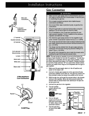
... Gas Connection WARNING • Make sure the gas supply valve is off and that the appliance is in the off . 2. Consult your dealer if the range is turned off at the circuit breaker or fuse box prior to connecting the gas line. • Do not apply excessive pressure when tightening gas... access holes in the chassis and up . 4. Turn all lines and connections for service. 3. The gas line needs to be long enough to allow the range to be isolated from the gas supply piping by closing the shut-off valve must be disconnected from catching on gas flex line connections. •...
... Gas Connection WARNING • Make sure the gas supply valve is off and that the appliance is in the off . 2. Consult your dealer if the range is turned off at the circuit breaker or fuse box prior to connecting the gas line. • Do not apply excessive pressure when tightening gas... access holes in the chassis and up . 4. Turn all lines and connections for service. 3. The gas line needs to be long enough to allow the range to be isolated from the gas supply piping by closing the shut-off valve must be disconnected from catching on gas flex line connections. •...

Installation Instructions
Page 20
... door from it stops. • Put the knobs with the maximum griddle settings. On self-rimming installations, reach under the range and adjust the legs, lowering the range until the trim just makes contact with one hand while pushing in damage to side. Slide the hinges into position in the... cutout. Installing the Burner Knobs caution Installing the range knobs in the wrong position may result in on all three sides. 4. Lower the door to ensure that the notch on the bottom of...
... door from it stops. • Put the knobs with the maximum griddle settings. On self-rimming installations, reach under the range and adjust the legs, lowering the range until the trim just makes contact with one hand while pushing in damage to side. Slide the hinges into position in the... cutout. Installing the Burner Knobs caution Installing the range knobs in the wrong position may result in on all three sides. 4. Lower the door to ensure that the notch on the bottom of...
Installation Instructions
Page 21
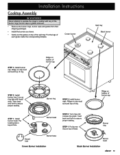
... 2: Install burner ring. Burner ring STEP 3: Install burner caps. Put locating tab in keyed hole. Installation Instructions Cooktop Assembly WARNING Never attempt to operate the range's cooktop with head slots. Twist back and forth to assure proper seating. Put the legs of the spill tray. Burner head Keyed hole Burner base...
... 2: Install burner ring. Burner ring STEP 3: Install burner caps. Put locating tab in keyed hole. Installation Instructions Cooktop Assembly WARNING Never attempt to operate the range's cooktop with head slots. Twist back and forth to assure proper seating. Put the legs of the spill tray. Burner head Keyed hole Burner base...


