
Planning Guides
Page 1
www.Dacor.com Phone: (800) 7935-0.7093 Width at front panel: 29 7/8" (758 mm) 35 3/4" (908 mm) to 37 7/8" (962 mm) 1 9/16" (40 mm) Width at front ... trim 1 5/16" (33 mm) to cooking surface (top of grates) from bottom of trim 35 3/4" (908 mm) to change without notice. Document # PG05-003 ER30D, ER30DSR Epicure® Ranges Revised 02/03/11 Page 1/3 PLANNING GUIDE 46 1/4" (1175 mm) 28 13/16" (732 mm) 27 5/16" (694 mm) 26 5/16" (668 mm...
www.Dacor.com Phone: (800) 7935-0.7093 Width at front panel: 29 7/8" (758 mm) 35 3/4" (908 mm) to 37 7/8" (962 mm) 1 9/16" (40 mm) Width at front ... trim 1 5/16" (33 mm) to cooking surface (top of grates) from bottom of trim 35 3/4" (908 mm) to change without notice. Document # PG05-003 ER30D, ER30DSR Epicure® Ranges Revised 02/03/11 Page 1/3 PLANNING GUIDE 46 1/4" (1175 mm) 28 13/16" (732 mm) 27 5/16" (694 mm) 26 5/16" (668 mm...

Planning Guides
Page 2
...3/4" (552 mm) 8 5/8" (219 mm) 10 3/16" (259 mm) 7/8"* (22 mm) B D Gas inlet Range electrical access, cover removed A C 7/8" (22 mm) Dia. Document # PG05-003 ER30D, ER30DSR Epicure® Ranges Revised 02/03/11 Page 2/3 PLANNING GUIDE Product tolerances: ±1/16" (±1.6 mm) unless otherwise stated GAS - GAS ... junction box/receptacle must allow for the following page for countertop/cabinet cutout dimensions for all models is the recommended location. www.Dacor.com Phone: (800) 7935-0.8093 This is 1/2 p.s.i. 18" (457 mm) Min.1, 4 Non-combustible surface along back ...
...3/4" (552 mm) 8 5/8" (219 mm) 10 3/16" (259 mm) 7/8"* (22 mm) B D Gas inlet Range electrical access, cover removed A C 7/8" (22 mm) Dia. Document # PG05-003 ER30D, ER30DSR Epicure® Ranges Revised 02/03/11 Page 2/3 PLANNING GUIDE Product tolerances: ±1/16" (±1.6 mm) unless otherwise stated GAS - GAS ... junction box/receptacle must allow for the following page for countertop/cabinet cutout dimensions for all models is the recommended location. www.Dacor.com Phone: (800) 7935-0.8093 This is 1/2 p.s.i. 18" (457 mm) Min.1, 4 Non-combustible surface along back ...

Planning Guides
Page 3
www.Dacor.com Phone: (800) 7935-0.9093 Document # PG05-003 ER30D, ER30DSR Epicure® Ranges Revised 02/03/11 Page 3/3 PLANNING GUIDE Non-combustible rear wall recommeded Cutout tolerances: +1/16", -0, (+1.6 mm, -0) unless otherwise stated 10" Min. (254...cutout dimensions self rimming installation TOP VIEW - Specifications subject to clear stiffener ERV30 or PRV30 raised vent 28 3/4" (730 mm) Countertop* ER30DSR range: ATK30SR trim kit required for installation with raised vent Cabinet face* Back of control panel Shown with optional 3-inch side panels installed** Countertop ...
www.Dacor.com Phone: (800) 7935-0.9093 Document # PG05-003 ER30D, ER30DSR Epicure® Ranges Revised 02/03/11 Page 3/3 PLANNING GUIDE Non-combustible rear wall recommeded Cutout tolerances: +1/16", -0, (+1.6 mm, -0) unless otherwise stated 10" Min. (254...cutout dimensions self rimming installation TOP VIEW - Specifications subject to clear stiffener ERV30 or PRV30 raised vent 28 3/4" (730 mm) Countertop* ER30DSR range: ATK30SR trim kit required for installation with raised vent Cabinet face* Back of control panel Shown with optional 3-inch side panels installed** Countertop ...
Installation Instructions
Page 1
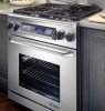
Installation Instructions Epicure® Range For use with models ER30D, ER30D-C, ER30DSR Part No. 102187 Rev. J THIS APPLIANCE HAS BEEN TESTED IN ACCORDANCE WITH THE LATEST EDITION OF ANSI Z21.1 STANDARD FOR HOUSEHOLD GAS COOKING APPLIANCES.
Installation Instructions Epicure® Range For use with models ER30D, ER30D-C, ER30DSR Part No. 102187 Rev. J THIS APPLIANCE HAS BEEN TESTED IN ACCORDANCE WITH THE LATEST EDITION OF ANSI Z21.1 STANDARD FOR HOUSEHOLD GAS COOKING APPLIANCES.

Installation Instructions
Page 3
... monoxide poisoning. WARNING WARNING - Also keep items that WILL result in place so children cannot easily climb inside or outside of the range or cover an entire rack with materials such as aerosol cans, away from the old appliance. READ AND SAVE THESE INSTRUCTIONS 1 Doing..., in this or any other appliance. Do not store flammable or explosive materials in minor personal injury or property damage. Always contact the Dacor Customer Service Team about problems and conditions that can cause a child entrapment and suffocation hazard. Safety Symbols in your building. • From...
... monoxide poisoning. WARNING WARNING - Also keep items that WILL result in place so children cannot easily climb inside or outside of the range or cover an entire rack with materials such as aerosol cans, away from the old appliance. READ AND SAVE THESE INSTRUCTIONS 1 Doing..., in this or any other appliance. Do not store flammable or explosive materials in minor personal injury or property damage. Always contact the Dacor Customer Service Team about problems and conditions that can cause a child entrapment and suffocation hazard. Safety Symbols in your building. • From...

Installation Instructions
Page 4
... Safety Instructions General Safety Precautions To reduce the risk of fire, explosion, electric shock, serious injury or death when installing or using the range. Do not allow clothing to turn off . • NEVER block or cover any type of service or installation, make sure these installation..., can cause suffocation. • If you receive a damaged product, immediately contact your safety, do not use a damaged appliance. • This range must be hot. Plastic sheets and bags can be harmful to the gas supply without the convection filter installed. Do not install or use long...
... Safety Instructions General Safety Precautions To reduce the risk of fire, explosion, electric shock, serious injury or death when installing or using the range. Do not allow clothing to turn off . • NEVER block or cover any type of service or installation, make sure these installation..., can cause suffocation. • If you receive a damaged product, immediately contact your safety, do not use a damaged appliance. • This range must be hot. Plastic sheets and bags can be harmful to the gas supply without the convection filter installed. Do not install or use long...

Installation Instructions
Page 6
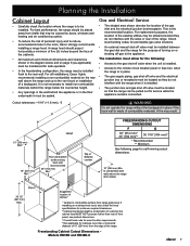
... • Freestanding ranges equipped for high altitude operation. The appliance cord must: ◊ Be UL listed type SRD or SRDT ◊ Be equipped with the selfrimming option. Refer to the appliance from the wall for service, while remaining connected. ER30D/ER30DSR ELECTRICAL SPECIFICATIONS ...the appliance being installed is protected by a licensed electrician as specified below prior to freestanding units equipped for reference only - The range ships with the National Fuel Gas Code ANSI Z223.1. • Be certain that the required 4 wire electrical outlet is equipped...
... • Freestanding ranges equipped for high altitude operation. The appliance cord must: ◊ Be UL listed type SRD or SRDT ◊ Be equipped with the selfrimming option. Refer to the appliance from the wall for service, while remaining connected. ER30D/ER30DSR ELECTRICAL SPECIFICATIONS ...the appliance being installed is protected by a licensed electrician as specified below prior to freestanding units equipped for reference only - The range ships with the National Fuel Gas Code ANSI Z223.1. • Be certain that the required 4 wire electrical outlet is equipped...
Installation Instructions
Page 7
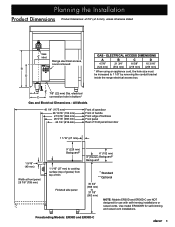
...10 3/16" (259 mm) * When using an appliance cord, the hole size must be increased to 37 7/8" (962 mm) NOTE: Models ER30D and ER30D-C are NOT designed for self-rimming and raised vent installations. All Models 46 1/4" (1175 mm) 28 13/16" (732 mm) 27 5/16... top of trim Finished side panel * Standard ** Optional 35 3/4" (908 mm) to 1 1/8" by removing the conduit bracket inside the range electrical access box. Freestanding Models: ER30D and ER30D-C 5 A C 7/8" (22 mm) Dia. Planning the Installation Product Dimensions Product tolerances: ±1/16" (±1.6 mm), unless otherwise ...
...10 3/16" (259 mm) * When using an appliance cord, the hole size must be increased to 37 7/8" (962 mm) NOTE: Models ER30D and ER30D-C are NOT designed for self-rimming and raised vent installations. All Models 46 1/4" (1175 mm) 28 13/16" (732 mm) 27 5/16... top of trim Finished side panel * Standard ** Optional 35 3/4" (908 mm) to 1 1/8" by removing the conduit bracket inside the range electrical access box. Freestanding Models: ER30D and ER30D-C 5 A C 7/8" (22 mm) Dia. Planning the Installation Product Dimensions Product tolerances: ±1/16" (±1.6 mm), unless otherwise ...
Installation Instructions
Page 9
... height. • Any openings in the wall behind the appliance or in the room, Dacor strongly recommends installing a range hood. Cutout tolerances: +1/16" (+1.6 mm), -0 F WARNING Do not operate the range without the backguard in place. • The gas supply piping, gas shut-off valve ... rear wall. Freestanding Cabinet Cutout Dimensions Models ER30D and ER30D-C 7 Check local building codes for permissible gas valve locations. • An external manual shut-off valve must be located so they do not interfere with the range when it must be maintained for self-rimming...
... height. • Any openings in the wall behind the appliance or in the room, Dacor strongly recommends installing a range hood. Cutout tolerances: +1/16" (+1.6 mm), -0 F WARNING Do not operate the range without the backguard in place. • The gas supply piping, gas shut-off valve ... rear wall. Freestanding Cabinet Cutout Dimensions Models ER30D and ER30D-C 7 Check local building codes for permissible gas valve locations. • An external manual shut-off valve must be located so they do not interfere with the range when it must be maintained for self-rimming...

Installation Instructions
Page 10
... proceeding with Raised Vent Notes For All Self-Rimming Installations: • On installations without a raised vent (see above right), install Dacor trim kit ATK30SR. When sliding the range into place. The range trim will stop when the rear of the control panel contacts the notches toward the front of the countertop. Self-Rimming...
... proceeding with Raised Vent Notes For All Self-Rimming Installations: • On installations without a raised vent (see above right), install Dacor trim kit ATK30SR. When sliding the range into place. The range trim will stop when the rear of the control panel contacts the notches toward the front of the countertop. Self-Rimming...
Installation Instructions
Page 11
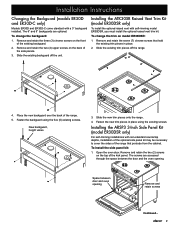
Installation Instructions Changing the Backguard (models ER30D and ER30D-C only) Models ER30D and ER30D-C come standard with self-rimming model ER30DSR, you must install the optional raised vent trim kit. Remove and retain the seven (7) chrome screws that...place. 2. To install the side panel kit: 1. To change the backguard: 1. Fasten the backguard using the existing screws. Slide the existing backguard off the range. 4. Space between the door and the oven opening Remove and retain screws Continued... 9 To change the trim on the front of the kick panel. Remove...
Installation Instructions Changing the Backguard (models ER30D and ER30D-C only) Models ER30D and ER30D-C come standard with self-rimming model ER30DSR, you must install the optional raised vent trim kit. Remove and retain the seven (7) chrome screws that...place. 2. To install the side panel kit: 1. To change the backguard: 1. Fasten the backguard using the existing screws. Slide the existing backguard off the range. 4. Space between the door and the oven opening Remove and retain screws Continued... 9 To change the trim on the front of the kick panel. Remove...
Installation Instructions
Page 12
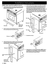
...side of the side panel. Three (3) hex head screws attach the side. Repeat steps 3 to the range. NOTE: There is not reused as shown below. Pull the kick panel free from the kit to ...kick panel as with the left side panel in the front panel to attach the bottom of the range. Hold the left side (do not perform step 4). Hex screw Kick panel Remove and retain screw,... End cap 7. One (1) Torx head screw (83709) inserts through a hole in position on the range. 6. Close the door. Torx screw Torx screw Front panel 4. Remove and retain the two screws from under the ...
...side of the side panel. Three (3) hex head screws attach the side. Repeat steps 3 to the range. NOTE: There is not reused as shown below. Pull the kick panel free from the kit to ...kick panel as with the left side panel in the front panel to attach the bottom of the range. Hold the left side (do not perform step 4). Hex screw Kick panel Remove and retain screw,... End cap 7. One (1) Torx head screw (83709) inserts through a hole in position on the range. 6. Close the door. Torx screw Torx screw Front panel 4. Remove and retain the two screws from under the ...
Installation Instructions
Page 13
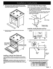
... and does not actually attach to the range by snapping the ball studs on the back of the range. With the door closed, reattach the kick panel to the range itself. See the diagram above for final installation: • For model ER30D and ER30D-C, adjust the height until it until the... top edge of the trim around the edge of the of range 2 1/8" * up down * Distance to floor: 2 7/16" ...
... and does not actually attach to the range by snapping the ball studs on the back of the range. With the door closed, reattach the kick panel to the range itself. See the diagram above for final installation: • For model ER30D and ER30D-C, adjust the height until it until the... top edge of the trim around the edge of the of range 2 1/8" * up down * Distance to floor: 2 7/16" ...
Installation Instructions
Page 14
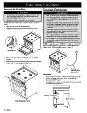
...range electrical box unless instructed to do so in the Verifying Proper Operation section of these instructions. • Improper connection of range... Put slack in compliance with local ordinances. • Do not turn on power to the range...• Wire the range only in electrical wiring and gas ...is long enough to allow the range to be connected to a ...the appliance. NOTE: Freestanding model ER30D-C is not responsible for damages... lift. If installing a pre-wired range, skip to its fully opened position.... vertical position. 4. To make the range easier to move, remove the door to...
...range electrical box unless instructed to do so in the Verifying Proper Operation section of these instructions. • Improper connection of range... Put slack in compliance with local ordinances. • Do not turn on power to the range...• Wire the range only in electrical wiring and gas ...is long enough to allow the range to be connected to a ...the appliance. NOTE: Freestanding model ER30D-C is not responsible for damages... lift. If installing a pre-wired range, skip to its fully opened position.... vertical position. 4. To make the range easier to move, remove the door to...
Installation Instructions
Page 15
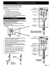
...wire Conduit strain relief nut Loop and spade terminal connections 4 Wire Conduit Connection 13 If using a 4 wire connection, connect the green wire to wire the range: • 4 wire conduit • 3 wire conduit (where local codes permit) • 4 wire appliance cord (where local codes permit) •... 3 wire appliance cord (where local codes permit) The sections below and on the bottom of the range. Replace the range electrical access cover. L1 terminal Neutral terminal Jumper link L2 terminal Black wire White wire Red wire Conduit strain relief nut 3 Wire...
...wire Conduit strain relief nut Loop and spade terminal connections 4 Wire Conduit Connection 13 If using a 4 wire connection, connect the green wire to wire the range: • 4 wire conduit • 3 wire conduit (where local codes permit) • 4 wire appliance cord (where local codes permit) •... 3 wire appliance cord (where local codes permit) The sections below and on the bottom of the range. Replace the range electrical access cover. L1 terminal Neutral terminal Jumper link L2 terminal Black wire White wire Red wire Conduit strain relief nut 3 Wire...
Installation Instructions
Page 16
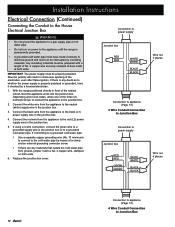
With the range positioned directly in continuous sparking of No. 4 copper wire securely clamped to bare metal at both ends. 6. Connect the black wire from the appliance to ... the cold water pipe by a licensed electrician. 1. Any insulating materials must be jumpered with a No. 4 copper wire, clamped on power to the appliance until the range is properly polarized or grounded, have metal continuity to Junction Box 14
With the range positioned directly in continuous sparking of No. 4 copper wire securely clamped to bare metal at both ends. 6. Connect the black wire from the appliance to ... the cold water pipe by a licensed electrician. 1. Any insulating materials must be jumpered with a No. 4 copper wire, clamped on power to the appliance until the range is properly polarized or grounded, have metal continuity to Junction Box 14
Installation Instructions
Page 18
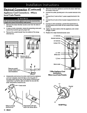
... the L2 wire to the grounding screw inside the box. Replace the range electrical access cover. Where Local Code Permits L1 Neutral Bottom of the range electrical box. 5. Remove the range electrical access cover from the bottom of range electrical box 16 Reassemble with tabs below the box and the strain relief...50P Plug Connect the L1 wire to the neutral terminal in the box. 9. Disassemble and remove the strain relief from the bottom of the range. 2. L1 terminal Neutral terminal L2 terminal Jumper link Remove link on the two parts of the box and reassemble it so that the ...
... the L2 wire to the grounding screw inside the box. Replace the range electrical access cover. Where Local Code Permits L1 Neutral Bottom of the range electrical box. 5. Remove the range electrical access cover from the bottom of range electrical box 16 Reassemble with tabs below the box and the strain relief...50P Plug Connect the L1 wire to the neutral terminal in the box. 9. Disassemble and remove the strain relief from the bottom of the range. 2. L1 terminal Neutral terminal L2 terminal Jumper link Remove link on the two parts of the box and reassemble it so that the ...
Installation Instructions
Page 19
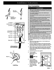
...Gas line 7. off valve previously installed on the gas line as you push it up. 4. Access holes Back of gas available, check the range rating label (see page 3 for service. 3. OFF Icon Regulator connection 6. Installation Instructions Bare wire connections Loop and spade terminal connections L1 terminal ... for gas leaks as instructed below 1/2 p.s.i. (3.5 kPa). • Be careful not to damage the wires inside the access holes to the range is compatible with LP gas will have its own high pressure regulator. Slide the gas line up through the access holes. Turn on the gas...
...Gas line 7. off valve previously installed on the gas line as you push it up. 4. Access holes Back of gas available, check the range rating label (see page 3 for service. 3. OFF Icon Regulator connection 6. Installation Instructions Bare wire connections Loop and spade terminal connections L1 terminal ... for gas leaks as instructed below 1/2 p.s.i. (3.5 kPa). • Be careful not to damage the wires inside the access holes to the range is compatible with LP gas will have its own high pressure regulator. Slide the gas line up through the access holes. Turn on the gas...

Installation Instructions
Page 20
... plastic coating off its hinges: • Make sure that the notch on the bottom of hinge receptacle Door Installation 18 Carefully slide the range into the hinge openings, resting the bottom of the door. 1. Readjust the legs if necessary. The knobs for the right burners are ...Oven Door WARNING To avoid personal injury or damage to the fully opened position. 3. Rotate the two hinge locks toward the front of the range immediately after installation of the hinge arms on each hinge receptacle. 2. Installation Instructions Final Installation 1. Push until it at a 15° ...
... plastic coating off its hinges: • Make sure that the notch on the bottom of hinge receptacle Door Installation 18 Carefully slide the range into the hinge openings, resting the bottom of the door. 1. Readjust the legs if necessary. The knobs for the right burners are ...Oven Door WARNING To avoid personal injury or damage to the fully opened position. 3. Rotate the two hinge locks toward the front of the range immediately after installation of the hinge arms on each hinge receptacle. 2. Installation Instructions Final Installation 1. Push until it at a 15° ...
Installation Instructions
Page 21
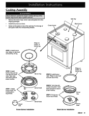
... tray. Burner ring Burner head Stack Burner Installation 19 Burner ring STEP 3: Install burner caps. Installation Instructions Cooktop Assembly WARNING Never attempt to operate the range's cooktop with head slots.
... tray. Burner ring Burner head Stack Burner Installation 19 Burner ring STEP 3: Install burner caps. Installation Instructions Cooktop Assembly WARNING Never attempt to operate the range's cooktop with head slots.


