
Planning Guides
Page 1
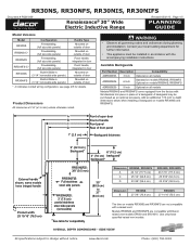
... Wide Electric Inductive Range Revised 03/21/13 Page 1/5 PLANNING GUIDE Model Versions Model Configuration Handle Type RR30NS Freestanding, (full size side panels) Mounted on outside of door RR30NS-C* Freestanding, (full size side panels) Mounted on outside of door RR30NFS Freestanding, (full ...) Dimension B RR30NS 27 7/8" (70.8 cm) RR30NIS 27 11/16" (70.3 cm) The trim on models RR30NS and RR30NFS are compatible with Dacor raised vent models ERV30 and ERV3015. side view All specifications subject to depth dimensions below when installing a backguard on all governing codes...
... Wide Electric Inductive Range Revised 03/21/13 Page 1/5 PLANNING GUIDE Model Versions Model Configuration Handle Type RR30NS Freestanding, (full size side panels) Mounted on outside of door RR30NS-C* Freestanding, (full size side panels) Mounted on outside of door RR30NFS Freestanding, (full ...) Dimension B RR30NS 27 7/8" (70.8 cm) RR30NIS 27 11/16" (70.3 cm) The trim on models RR30NS and RR30NFS are compatible with Dacor raised vent models ERV30 and ERV3015. side view All specifications subject to depth dimensions below when installing a backguard on all governing codes...
Planning Guides
Page 2
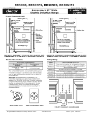
...notice. Factory Wiring Model RR30NS RR30NS-C RR30NFS RR30NFS-C RR30NIS RR30NIFS Factory Electrical Connection Power cord...RR30NFS, RR30NIS, RR30NIFS Document # PG05-009 Renaissance 30" Wide Electric Inductive Range...Range trim resting on countertop 27 9/16" (70.0 cm) 3/8" min. (1.0 cm) flat countertop overhang Range trim resting on the product data label. Not for freestanding ranges...Models RR30NS-C and RR30NFS-C are freestanding ranges that come with ...to clear stiffener RR30NI[F]S range Cabinet face Back of ... range All specifications subject to clear stiffener RR30NI[F]S range ...
...notice. Factory Wiring Model RR30NS RR30NS-C RR30NFS RR30NFS-C RR30NIS RR30NIFS Factory Electrical Connection Power cord...RR30NFS, RR30NIS, RR30NIFS Document # PG05-009 Renaissance 30" Wide Electric Inductive Range...Range trim resting on countertop 27 9/16" (70.0 cm) 3/8" min. (1.0 cm) flat countertop overhang Range trim resting on the product data label. Not for freestanding ranges...Models RR30NS-C and RR30NFS-C are freestanding ranges that come with ...to clear stiffener RR30NI[F]S range Cabinet face Back of ... range All specifications subject to clear stiffener RR30NI[F]S range ...

Planning Guides
Page 3
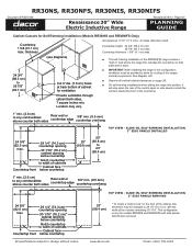
... following page for minimum required clearances. 2Cabinet/countertop depth is the suggested location. www.dacor.com Phone: (800) 793-0093 If installing range hood, check the hood specifications for self-rimming installations. See the range hood specifications for rear wall surface requirements. RR30NS, RR30NFS, RR30NIS, RR30NIFS Document # PG05-009 Renaissance 30" Wide Electric Inductive...
... following page for minimum required clearances. 2Cabinet/countertop depth is the suggested location. www.dacor.com Phone: (800) 793-0093 If installing range hood, check the hood specifications for self-rimming installations. See the range hood specifications for rear wall surface requirements. RR30NS, RR30NFS, RR30NIS, RR30NIFS Document # PG05-009 Renaissance 30" Wide Electric Inductive...
Planning Guides
Page 4
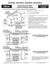
... cabient both sides Rear wall or countertop edge 3/8" min. (9.5 mm) countertop overhang Top View - RR30NS, RR30NFS, RR30NIS, RR30NIFS Document # PG05-009 Renaissance 30" Wide Electric Inductive Range Revised 03/19/13 Page 4/5 PLANNING GUIDE Cabinet Cutouts for ventilation. Countertop front 29 1/4" (74.3 cm)...the range into position, it will stop when the rear of the control panel or side panels contact the notches toward the front of cabinet for Self-Rimming Installation (Models RR30NIS and RR30NIFS Only) All tolerances +1/16" (+1.6 mm), -0 unless otherwise noted. www.dacor.com...
... cabient both sides Rear wall or countertop edge 3/8" min. (9.5 mm) countertop overhang Top View - RR30NS, RR30NFS, RR30NIS, RR30NIFS Document # PG05-009 Renaissance 30" Wide Electric Inductive Range Revised 03/19/13 Page 4/5 PLANNING GUIDE Cabinet Cutouts for ventilation. Countertop front 29 1/4" (74.3 cm)...the range into position, it will stop when the rear of the control panel or side panels contact the notches toward the front of cabinet for Self-Rimming Installation (Models RR30NIS and RR30NIFS Only) All tolerances +1/16" (+1.6 mm), -0 unless otherwise noted. www.dacor.com...
Planning Guides
Page 5
..., left. ■■ Observe all vertical cabinet clearances on both sides, 7 square inches min. RR30NS, RR30NFS, RR30NIS, RR30NIFS Document # PG05-009 Renaissance 30" Wide Electric Inductive Range Revised 03/19/13 Page 5/5 PLANNING GUIDE Cabinet Cutouts for ventilation. Countertop thickness: 1 5/8" (4.1 cm)... holes at the notches remaining 30 1/16". thickness Countertop height: 34 3/4" (88.3 cm) min. 36 7/8" (93.7 cm) max. www.dacor.com Phone: (800) 793-0093 Downdraft ERV30[15] with Slide-In, Self-Rimming Installation, 3" Side Panels Removed * To create a "built-in...
..., left. ■■ Observe all vertical cabinet clearances on both sides, 7 square inches min. RR30NS, RR30NFS, RR30NIS, RR30NIFS Document # PG05-009 Renaissance 30" Wide Electric Inductive Range Revised 03/19/13 Page 5/5 PLANNING GUIDE Cabinet Cutouts for ventilation. Countertop thickness: 1 5/8" (4.1 cm)... holes at the notches remaining 30 1/16". thickness Countertop height: 34 3/4" (88.3 cm) min. 36 7/8" (93.7 cm) max. www.dacor.com Phone: (800) 793-0093 Downdraft ERV30[15] with Slide-In, Self-Rimming Installation, 3" Side Panels Removed * To create a "built-in...

Installation Instructions
Page 1
Installation Instructions Renaissance® Electric Range with induction cooktop Models: RR30NS, RR30NS-C, RR30NFS, RR30NFS-C, RR30NIS and RR30NIFS Part No. 105910 Rev. A
Installation Instructions Renaissance® Electric Range with induction cooktop Models: RR30NS, RR30NS-C, RR30NFS, RR30NFS-C, RR30NIS and RR30NIFS Part No. 105910 Rev. A
Installation Instructions
Page 2
... Bracket 8 Backguard Installation 10 Raised Vent Installation 10 Removing the Oven Door 10 Electrical Connection 10 Installing the Range 16 Re-installing the Oven Door 16 Verifying Proper Operation 17 IMPORTANT: • Installer: In the interest of... or the Dacor Customer Service Team. Flush handle, Power cord not included. Leave these installation instructions with flashlight) Model Identification Model Configuration* Handle Type Electrical Connection** RR30NS RR30NS-C RR30NFS RR30NFS-C RR30NIS RR30NIFS Freestanding, (full size side panels), 6-inch backguard standard ...
... Bracket 8 Backguard Installation 10 Raised Vent Installation 10 Removing the Oven Door 10 Electrical Connection 10 Installing the Range 16 Re-installing the Oven Door 16 Verifying Proper Operation 17 IMPORTANT: • Installer: In the interest of... or the Dacor Customer Service Team. Flush handle, Power cord not included. Leave these installation instructions with flashlight) Model Identification Model Configuration* Handle Type Electrical Connection** RR30NS RR30NS-C RR30NFS RR30NFS-C RR30NIS RR30NIFS Freestanding, (full size side panels), 6-inch backguard standard ...
Installation Instructions
Page 3
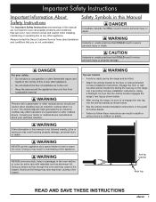
... Hazards or unsafe practices that COULD result in this appliance as aluminum foil. The electromagnetic field generated by sliding the rear leg on the range into the anti-tip bracket as directed in severe personal injury or death. Using a flashlight, be killed. • Attach the anti-...or any other medical device should use gasoline or other flammable vapors and liquids in severe personal injury or death. Always contact the Dacor Customer Service Team about your safety: • Do not store or use caution when standing near an induction cooktop when it according...
... Hazards or unsafe practices that COULD result in this appliance as aluminum foil. The electromagnetic field generated by sliding the rear leg on the range into the anti-tip bracket as directed in severe personal injury or death. Using a flashlight, be killed. • Attach the anti-...or any other medical device should use gasoline or other flammable vapors and liquids in severe personal injury or death. Always contact the Dacor Customer Service Team about your safety: • Do not store or use caution when standing near an induction cooktop when it according...
Installation Instructions
Page 5
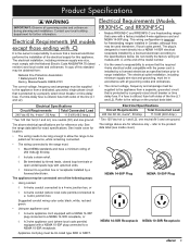
... NEMA 10-50R Receptacle 3 Contact your local building department for service, while remaining connected. • The wiring connected to the range must: ◊ Meet NEMA standards and have a minimum rating of the model number. • It is the owner's responsibility... Canada, although they may be used elsewhere, if local codes permit. Electrical Requirements (Models RR30NS-C and RR30NFS-C) • Models RR30NS-C and RR30NFS-C are freestanding ranges that is utilized, fuse both sides of the electrical supply for reference only - The ratings above electrical specifications...
... NEMA 10-50R Receptacle 3 Contact your local building department for service, while remaining connected. • The wiring connected to the range must: ◊ Meet NEMA standards and have a minimum rating of the model number. • It is the owner's responsibility... Canada, although they may be used elsewhere, if local codes permit. Electrical Requirements (Models RR30NS-C and RR30NFS-C) • Models RR30NS-C and RR30NFS-C are freestanding ranges that is utilized, fuse both sides of the electrical supply for reference only - The ratings above electrical specifications...

Installation Instructions
Page 7
... should project horizontally a minimum of five (5) inches beyond the face of front panel. Dacor recommends installing a non-combustible material on the following pages must be located so the range can be removed for minimum required clearances. 2Cabinet/countertop depth is installed and under the .... • The electrical junction box/receptacle must be installed flush to reduce accumulated smoke in the room, Dacor strongly recommends installing a range hood. Cabinet and Countertop Preparation • To reduce the risk of the cooking surface to power. If installing...
... should project horizontally a minimum of five (5) inches beyond the face of front panel. Dacor recommends installing a non-combustible material on the following pages must be located so the range can be removed for minimum required clearances. 2Cabinet/countertop depth is installed and under the .... • The electrical junction box/receptacle must be installed flush to reduce accumulated smoke in the room, Dacor strongly recommends installing a range hood. Cabinet and Countertop Preparation • To reduce the risk of the cooking surface to power. If installing...

Installation Instructions
Page 8
... is only for Self-Rimming Installation (Models RR30NIS and RR30NIFS Only) Countertop 1 5/8 (41.1 cm) • max. IMPORTANT: When installing the range in back. thickness (see diagrams) • 34 3/4" (88.3 cm) to any combustibles above counter both sides Rear wall or countertop edge 3/8"... min. (9.5 mm) countertop overhang The self-rimming installation of the RR30NI[F]S range creates a "built-in" look " on page 5. Location may be provided to allow for ventilation. Installation Specifications Cabinet Cutouts for ...
... is only for Self-Rimming Installation (Models RR30NIS and RR30NIFS Only) Countertop 1 5/8 (41.1 cm) • max. IMPORTANT: When installing the range in back. thickness (see diagrams) • 34 3/4" (88.3 cm) to any combustibles above counter both sides Rear wall or countertop edge 3/8"... min. (9.5 mm) countertop overhang The self-rimming installation of the RR30NI[F]S range creates a "built-in" look " on page 5. Location may be provided to allow for ventilation. Installation Specifications Cabinet Cutouts for ...

Installation Instructions
Page 9
... with the side panels behind the door removed. This configuration is required for proper installation of a raised vent with a raised vent, when sliding the range into position, it will cover the front of cabinets Cabinet face below countertop 23 3/8" (59.4 cm) * To create a "built-in this dimension... 3" Side Panels Installed 1" min. (2.6 cm) to 23 3/8" (59.4 cm) Top View - Observe all vertical cabinet clearances on the back of the range, will stop when the rear of the control panel or side panels contact the notches toward the front of the countertop. 27 1/2" (69.9 cm) raised...
... with the side panels behind the door removed. This configuration is required for proper installation of a raised vent with a raised vent, when sliding the range into position, it will cover the front of cabinets Cabinet face below countertop 23 3/8" (59.4 cm) * To create a "built-in this dimension... 3" Side Panels Installed 1" min. (2.6 cm) to 23 3/8" (59.4 cm) Top View - Observe all vertical cabinet clearances on the back of the range, will stop when the rear of the control panel or side panels contact the notches toward the front of the countertop. 27 1/2" (69.9 cm) raised...

Installation Instructions
Page 10
...slab) for attaching the antitip bracket to ensure proper installation before proceeding. • Use and care manual • Anti-tip bracket with range ** Not included. There are provided along with a pencil. 3. Insert the screws through any existing floor covering down to the concrete ... Concrete anchors shown, do not use the wall mount option, the range front panel must be purchased separately ** * Included with screws and anchors • Oven racks (2) • Razor blade scraper • Dacor Cooktop Cleaning Cream Installing the Anti-Tip Bracket Locate the anti-tip ...
...slab) for attaching the antitip bracket to ensure proper installation before proceeding. • Use and care manual • Anti-tip bracket with range ** Not included. There are provided along with a pencil. 3. Insert the screws through any existing floor covering down to the concrete ... Concrete anchors shown, do not use the wall mount option, the range front panel must be purchased separately ** * Included with screws and anchors • Oven racks (2) • Razor blade scraper • Dacor Cooktop Cleaning Cream Installing the Anti-Tip Bracket Locate the anti-tip ...

Installation Instructions
Page 11
... bracket, based on both dots with 1/8" diameter drill bit, drill four 1 5/8" deep pilot holes perpendicular to 26 1/4 (66.7 cm) CL Range front panel CL Range front panel 10 1/2" (26.3 cm) 2 3/16" (5.6 cm) 11 1/2" (29.2 cm) Bracket center line Top View - To install the...#12 x 1 3/4 screws. Using a drill with a 1/16" drill bit. Determine the location of Wall Mounted Anti-Tip Bracket 9 Location of the range center line and front panel when the range is high enough: a. Anti-tip bracket Drywall Notch Wall Base plate #8 x 1", #8 x 1 1/4" or #12 x 1 3/4 screw, 4 places...
... bracket, based on both dots with 1/8" diameter drill bit, drill four 1 5/8" deep pilot holes perpendicular to 26 1/4 (66.7 cm) CL Range front panel CL Range front panel 10 1/2" (26.3 cm) 2 3/16" (5.6 cm) 11 1/2" (29.2 cm) Bracket center line Top View - To install the...#12 x 1 3/4 screws. Using a drill with a 1/16" drill bit. Determine the location of Wall Mounted Anti-Tip Bracket 9 Location of the range center line and front panel when the range is high enough: a. Anti-tip bracket Drywall Notch Wall Base plate #8 x 1", #8 x 1 1/4" or #12 x 1 3/4 screw, 4 places...

Installation Instructions
Page 12
... oven. NOTE: Model numbers ending with both hands just below the handle and pull it before moving the range into position. Lift the oven door to reduce weight. Dacor is connected to wire the range: • 4-wire conduit • 3-wire conduit (where local codes permit) • 4-wire appliance cord (where local codes permit...
... oven. NOTE: Model numbers ending with both hands just below the handle and pull it before moving the range into position. Lift the oven door to reduce weight. Dacor is connected to wire the range: • 4-wire conduit • 3-wire conduit (where local codes permit) • 4-wire appliance cord (where local codes permit...

Installation Instructions
Page 13
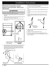
...over the wires and thread it onto the conduit strain relief inside the box. Connect the red wire to ground jumper link. 3. Remove the range electrical access cover from the conduit strain relief (not included). 4. If using a 4-wire connection, connect the green wire to the L1 power... supply terminal. 8. Replace the range electrical access cover. 3-Wire Conduit Connection Where Local Codes Permit L1 terminal Neutral terminal L2 terminal Link removed Grounding screw Red wire Green wire White...
...over the wires and thread it onto the conduit strain relief inside the box. Connect the red wire to ground jumper link. 3. Remove the range electrical access cover from the conduit strain relief (not included). 4. If using a 4-wire connection, connect the green wire to the L1 power... supply terminal. 8. Replace the range electrical access cover. 3-Wire Conduit Connection Where Local Codes Permit L1 terminal Neutral terminal L2 terminal Link removed Grounding screw Red wire Green wire White...

Installation Instructions
Page 14
... water pipe, use a separate copper grounding wire (No. 10 minimum) to connect to the red (L2) power supply wire inside the junction box. 2. With the range positioned directly in the junction box or to the black (L1) power supply wire inside the junction box. 3. Connect the red wire from the appliance...
... water pipe, use a separate copper grounding wire (No. 10 minimum) to connect to the red (L2) power supply wire inside the junction box. 2. With the range positioned directly in the junction box or to the black (L1) power supply wire inside the junction box. 3. Connect the red wire from the appliance...
Installation Instructions
Page 16
... 4. If using a loop or spade terminal. See facing page. 6. Remove the conduit bracket from the bottom of the range electrical box. 5. Remove the range electrical access cover from the appliance cord (not included). Connect the L1 wire to the grounding screw inside the box using ... (white) supply wire unless local building codes permit. 1. Replace the range electrical access cover. 12. Strain relief Bottom of the range. 2. Disassemble and remove the strain relief from the back of range electrical box 14 Reassemble with tabs below the box and the strain relief...
... 4. If using a loop or spade terminal. See facing page. 6. Remove the conduit bracket from the bottom of the range electrical box. 5. Remove the range electrical access cover from the appliance cord (not included). Connect the L1 wire to the grounding screw inside the box using ... (white) supply wire unless local building codes permit. 1. Replace the range electrical access cover. 12. Strain relief Bottom of the range. 2. Disassemble and remove the strain relief from the back of range electrical box 14 Reassemble with tabs below the box and the strain relief...

Installation Instructions
Page 18
...diagram below . 5. As you slide the unit into place the rear leg should engage the antitip bracket. 4. Use a level to make sure that the range does not tilt front to back or side to level and change the height if necessary. Lower the door to side. Rotate the two hinge...self-rimming configuration is slightly different from the floor to ensure that it at the desired height, based on the hinge receptacles. Carefully slide the range into the hinge openings, resting the bottom of the hinge arms on the cabinet and countertop installation. 2. Adjust the leveling legs to level ...
...diagram below . 5. As you slide the unit into place the rear leg should engage the antitip bracket. 4. Use a level to make sure that the range does not tilt front to back or side to level and change the height if necessary. Lower the door to side. Rotate the two hinge...self-rimming configuration is slightly different from the floor to ensure that it at the desired height, based on the hinge receptacles. Carefully slide the range into the hinge openings, resting the bottom of the hinge arms on the cabinet and countertop installation. 2. Adjust the leveling legs to level ...
Installation Instructions
Page 19
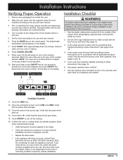
... operation been verified? 7. Dacor is the responsibility of the cooking elements. Press the BAKE key on the ON/OFF key for location. The default bake temperature should appear on power to make contact with all of the legs extended down (▼). After approximately three (3) minutes, check to the range at (800) 793...
... operation been verified? 7. Dacor is the responsibility of the cooking elements. Press the BAKE key on the ON/OFF key for location. The default bake temperature should appear on power to make contact with all of the legs extended down (▼). After approximately three (3) minutes, check to the range at (800) 793...


