
User's Guide
Page 3
... 8 24 1-Gigabit Ethernet Ports + 2 SFP Combo ports 8 48 1-Gigabit Ethernet Ports 8 Features 9 General Features 9 MAC Address Supported Features 11 Layer 2 Features 11 VLAN Supported Features 12 Class of Service (CoS) Features 12 Ethernet Switch Management Features 13 Port Default Settings 13 2 Hardware Description Switch Port Configurations 15 PowerConnect 2708/2716/2724/2748 Front Panel Port...
... 8 24 1-Gigabit Ethernet Ports + 2 SFP Combo ports 8 48 1-Gigabit Ethernet Ports 8 Features 9 General Features 9 MAC Address Supported Features 11 Layer 2 Features 11 VLAN Supported Features 12 Class of Service (CoS) Features 12 Ethernet Switch Management Features 13 Port Default Settings 13 2 Hardware Description Switch Port Configurations 15 PowerConnect 2708/2716/2724/2748 Front Panel Port...

User's Guide
Page 8
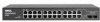
Figure 1-2. PowerConnect 2724 Front Panel The PowerConnect 2724 switch supports 24 GbE copper ports and has two SFP combo ports (1000BASE-SX or 1000BASE-LX). 48 1-Gigabit Ethernet Ports The following figure illustrates the PowerConnect 2716 front panel. Figure 1-4. PowerConnect 2748 Front Panel 8 16 1-Gigabit Ethernet Ports The following figure illustrates the PowerConnect 2748 front panel. Figure 1-3. PowerConnect 2716 Front Panel...
Figure 1-2. PowerConnect 2724 Front Panel The PowerConnect 2724 switch supports 24 GbE copper ports and has two SFP combo ports (1000BASE-SX or 1000BASE-LX). 48 1-Gigabit Ethernet Ports The following figure illustrates the PowerConnect 2716 front panel. Figure 1-4. PowerConnect 2748 Front Panel 8 16 1-Gigabit Ethernet Ports The following figure illustrates the PowerConnect 2748 front panel. Figure 1-3. PowerConnect 2716 Front Panel...

User's Guide
Page 17
...LED which indicates the Ethernet switch operational status. The two combo ports are logical ports with two physical connections: • An RJ-45 connection for Twisted Pair (TP) copper cabling • An SFP port for fiber connection. NOTE: Only one time. Figure 2-6. PowerConnect 2724 Front Panel On the ...front panel there are numbered 1 to 24, top down and left side of a combo port can switch from the RJ-45 to indicate the port status...
...LED which indicates the Ethernet switch operational status. The two combo ports are logical ports with two physical connections: • An RJ-45 connection for Twisted Pair (TP) copper cabling • An SFP port for fiber connection. NOTE: Only one time. Figure 2-6. PowerConnect 2724 Front Panel On the ...front panel there are numbered 1 to 24, top down and left side of a combo port can switch from the RJ-45 to indicate the port status...

User's Guide
Page 18
... front panel is powered on the front panel, sets the device management mode. NOTE: Only one of the two physical connections of a combo port can switch from the RJ-45 to indicate the port status. On each port, there are numbered 1 to 48, top down and left to right. If both... RJ-45 and SFP ports are determined by the physical connection used on a combo port, and utilizes the information in all the control interfaces. NOTE: The system can be disabled. PowerConnect 2748 Back Panel 18 PowerConnect 2748 Front Panel On the front panel, there are 48...
... front panel is powered on the front panel, sets the device management mode. NOTE: Only one of the two physical connections of a combo port can switch from the RJ-45 to indicate the port status. On each port, there are numbered 1 to 48, top down and left to right. If both... RJ-45 and SFP ports are determined by the physical connection used on a combo port, and utilizes the information in all the control interfaces. NOTE: The system can be disabled. PowerConnect 2748 Back Panel 18 PowerConnect 2748 Front Panel On the front panel, there are 48...

User's Guide
Page 21
SFP LED Indications LED Color Description Green Static Link is currently transmitting in Half Duplex mode. Table 2-5. The port .... • The device is set as the switch IP address. • Subnet mask changes to 255.255.255.0 • Graphical User Interface (GUI) login user name changes to factory default settings. Managed Mode Button The PowerConnect 2708/2716/2724/2748 has a Managed Mode push button on the...Flashing Amber Static Amber Flashing Off Right LED Green Static Off Description The port is linked at 1000 Mbps. SFP Port LED The following table describes the...
SFP LED Indications LED Color Description Green Static Link is currently transmitting in Half Duplex mode. Table 2-5. The port .... • The device is set as the switch IP address. • Subnet mask changes to 255.255.255.0 • Graphical User Interface (GUI) login user name changes to factory default settings. Managed Mode Button The PowerConnect 2708/2716/2724/2748 has a Managed Mode push button on the...Flashing Amber Static Amber Flashing Off Right LED Green Static Off Description The port is linked at 1000 Mbps. SFP Port LED The following table describes the...

User's Guide
Page 23
... the RJ-45 to the system administrator. Table 2-7. SFP Ports The PowerConnect 2724 switch supports two SFP transceivers combo ports, and the PowerConnect 2748 switch supports four SFP transceivers combo ports for 10/100/ 1000BASE-T Ethernet Port Pin No Function 1 TxRx 1+ 2 TxRx 1- 3 TxRx 2+ 4 TxRx 2- 5 TxRx 3+ 6 TxRx 3- 7 TxRx 4+ 8 TxRx 4- PowerConnect 2724 switch supports SFP diagnostics. RJ-45 Pin Number Allocation for various fiber...
... the RJ-45 to the system administrator. Table 2-7. SFP Ports The PowerConnect 2724 switch supports two SFP transceivers combo ports, and the PowerConnect 2748 switch supports four SFP transceivers combo ports for 10/100/ 1000BASE-T Ethernet Port Pin No Function 1 TxRx 1+ 2 TxRx 1- 3 TxRx 2+ 4 TxRx 2- 5 TxRx 3+ 6 TxRx 3- 7 TxRx 4+ 8 TxRx 4- PowerConnect 2724 switch supports SFP diagnostics. RJ-45 Pin Number Allocation for various fiber...

User's Guide
Page 24
... with receiver ground) 2 Transmitter fault 3 Transmitter disable; SFP Pin Connections Pin No Use 1 Transmitter ground (common with receiver ground) Power Connectors The PowerConnect 2708/2716/2724/2748 switches are powered by using the AC internal power supply. laser...high or open. 4 Module definition 2; Internal Power Supply Connector The PowerConnect 2708, PowerConnect 2716, PowerConnect 2724 and PowerConnect 2748 switch systems supports a single internal power supply to provide power for SFP Interfaces Table 2-8. The internal power supply supports input voltages between 100 ...
... with receiver ground) 2 Transmitter fault 3 Transmitter disable; SFP Pin Connections Pin No Use 1 Transmitter ground (common with receiver ground) Power Connectors The PowerConnect 2708/2716/2724/2748 switches are powered by using the AC internal power supply. laser...high or open. 4 Module definition 2; Internal Power Supply Connector The PowerConnect 2708, PowerConnect 2716, PowerConnect 2724 and PowerConnect 2748 switch systems supports a single internal power supply to provide power for SFP Interfaces Table 2-8. The internal power supply supports input voltages between 100 ...

User's Guide
Page 63
... Optical Transceivers Diagnostics in milliwatts. Voltage - Measured RX power in the tree view. Indicates that can be tested. 63 The optical transceiver provides access to PowerConnect 2724 device's SFP ports, which the cable is ready. NOTE: The Optical Transceivers Diagnostics analysis applies only to a set of parameters that the optical transceiver has achieved...
... Optical Transceivers Diagnostics in milliwatts. Voltage - Measured RX power in the tree view. Indicates that can be tested. 63 The optical transceiver provides access to PowerConnect 2724 device's SFP ports, which the cable is ready. NOTE: The Optical Transceivers Diagnostics analysis applies only to a set of parameters that the optical transceiver has achieved...

