
User's Guide
Page 3
... Address Supported Features 11 Layer 2 Features 11 VLAN Supported Features 12 Class of Service (CoS) Features 12 Ethernet Switch Management Features 13 Port Default Settings 13 2 Hardware Description Switch Port Configurations 15 PowerConnect 2708/2716/2724/2748 Front Panel Port Description . . . . 15 Physical Dimensions 19 LED Definitions 19 Power LED 19 Managed Mode LED...
... Address Supported Features 11 Layer 2 Features 11 VLAN Supported Features 12 Class of Service (CoS) Features 12 Ethernet Switch Management Features 13 Port Default Settings 13 2 Hardware Description Switch Port Configurations 15 PowerConnect 2708/2716/2724/2748 Front Panel Port Description . . . . 15 Physical Dimensions 19 LED Definitions 19 Power LED 19 Managed Mode LED...

User's Guide
Page 4
Power Connectors 24 Internal Power Supply Connector 24 3 Installing the Dell™ PowerConnect™ 27XX Installation Precautions 25 Overview 25 Site Requirements 26 Unpacking 26 Safety 26 Handling Static...the Network 32 4 Starting and Configuring the Dell™ PowerConnect™ 27XX Viewing Switch Operation 33 Initial Configuration 33 5 Using the Dell™ OpenManage™ Switch Administrator Understanding the Interface 37 Using the OpenManage Switch Administrator Buttons 39 Information Buttons 39 PowerConnect Switch Management Buttons 39 Starting the Application 40 ...
Power Connectors 24 Internal Power Supply Connector 24 3 Installing the Dell™ PowerConnect™ 27XX Installation Precautions 25 Overview 25 Site Requirements 26 Unpacking 26 Safety 26 Handling Static...the Network 32 4 Starting and Configuring the Dell™ PowerConnect™ 27XX Viewing Switch Operation 33 Initial Configuration 33 5 Using the Dell™ OpenManage™ Switch Administrator Understanding the Interface 37 Using the OpenManage Switch Administrator Buttons 39 Information Buttons 39 PowerConnect Switch Management Buttons 39 Starting the Application 40 ...

User's Guide
Page 5
Resetting the Device 41 Displaying Configuration on Demand 42 6 Configuring System Information Defining Switch Information 43 Viewing the Switch Status 43 Viewing System IP Address 44 Defining Interface Configuration 47 Viewing Jumbo Frames 49 Creating VLAN Membership 50 Defining VLAN Interface Settings 51 Configuring ...
Resetting the Device 41 Displaying Configuration on Demand 42 6 Configuring System Information Defining Switch Information 43 Viewing the Switch Status 43 Viewing System IP Address 44 Defining Interface Configuration 47 Viewing Jumbo Frames 49 Creating VLAN Membership 50 Defining VLAN Interface Settings 51 Configuring ...

User's Guide
Page 7
... maintaining the PowerConnect 2708, PowerConnect 2716, PowerConnect 2724, and PowerConnect 2748 Webmanaged Gigabit Ethernet switches. PowerConnect 2708 Front Panel The PowerConnect 2708 switch supports 8 GbE copper ports. 7 The switches are managed by Dell's OpenManage Switch Administrator. 8 1-Gigabit Ethernet Ports The following figure illustrates the PowerConnect 2708 front panel. System Description This section describes the hardware configurations of the PowerConnect 2708, PowerConnect 2716, PowerConnect 2724, and PowerConnect 2748. 1 Introduction...
... maintaining the PowerConnect 2708, PowerConnect 2716, PowerConnect 2724, and PowerConnect 2748 Webmanaged Gigabit Ethernet switches. PowerConnect 2708 Front Panel The PowerConnect 2708 switch supports 8 GbE copper ports. 7 The switches are managed by Dell's OpenManage Switch Administrator. 8 1-Gigabit Ethernet Ports The following figure illustrates the PowerConnect 2708 front panel. System Description This section describes the hardware configurations of the PowerConnect 2708, PowerConnect 2716, PowerConnect 2724, and PowerConnect 2748. 1 Introduction...

User's Guide
Page 8
... 16 GbE copper ports. 24 1-Gigabit Ethernet Ports + 2 SFP Combo ports The following figure illustrates the PowerConnect 2716 front panel. Figure 1-3. 16 1-Gigabit Ethernet Ports The following figure illustrates the PowerConnect 2724 front panel. PowerConnect 2724 Front Panel The PowerConnect 2724 switch supports 24 GbE copper ports and has two SFP combo ports (1000BASE-SX or 1000BASE-LX...
... 16 GbE copper ports. 24 1-Gigabit Ethernet Ports + 2 SFP Combo ports The following figure illustrates the PowerConnect 2716 front panel. Figure 1-3. 16 1-Gigabit Ethernet Ports The following figure illustrates the PowerConnect 2724 front panel. PowerConnect 2724 Front Panel The PowerConnect 2724 switch supports 24 GbE copper ports and has two SFP combo ports (1000BASE-SX or 1000BASE-LX...

User's Guide
Page 9
... the HOL blocking prevention mechanism is disabled on all times, except when QoS (Quality of 192.168.2.1. • Managed Mode - The switch does not have an IP address, nor is done by traffic competing for additional incoming traffic. From Unmanaged Mode, when the Managed Mode ... Managed Mode. To use Secure Mode, the user puts the switch in Managed Mode and then enabling Secure Mode. Management Modes • Unmanaged Mode - Once enabled, it is pressed, the switch enters Unmanaged Mode. • Secure Mode (PowerConnect 2748 only) - Secure Mode works by occupying the link so...
... the HOL blocking prevention mechanism is disabled on all times, except when QoS (Quality of 192.168.2.1. • Managed Mode - The switch does not have an IP address, nor is done by traffic competing for additional incoming traffic. From Unmanaged Mode, when the Managed Mode ... Managed Mode. To use Secure Mode, the user puts the switch in Managed Mode and then enabling Secure Mode. Management Modes • Unmanaged Mode - Once enabled, it is pressed, the switch enters Unmanaged Mode. • Secure Mode (PowerConnect 2748 only) - Secure Mode works by occupying the link so...

User's Guide
Page 10
...Cables (10BASE-T/100BASE-T/1000BASE-T), and is only done when the link is crossed or straight through. Auto Negotiation Auto negotiation allows an Ethernet switch to advertise modes of their transmission capabilities. The Jumbo Frames Support feature, utilizes the network optimally by the user. Standard wiring for end...auto negotiation function provides the means to an RJ-45 port is down. Jumbo Frames Support Jumbo frames are used for hubs and switches is automatically enabled for the entire system and cannot be halted temporarily, in order to 10K bytes. The main benefits of up to...
...Cables (10BASE-T/100BASE-T/1000BASE-T), and is only done when the link is crossed or straight through. Auto Negotiation Auto negotiation allows an Ethernet switch to advertise modes of their transmission capabilities. The Jumbo Frames Support feature, utilizes the network optimally by the user. Standard wiring for end...auto negotiation function provides the means to an RJ-45 port is down. Jumbo Frames Support Jumbo frames are used for hubs and switches is automatically enabled for the entire system and cannot be halted temporarily, in order to 10K bytes. The main benefits of up to...

User's Guide
Page 11
...flooded to all traffic passing through one or more source ports. Managed and Secure Modes VLAN-aware MAC-based Switching In Managed or Secure mode, the switch system always performs VLAN-aware bridging. Users can specify which no traffic is not performed (where frames are ... network links and the host operating system. 11 MAC Address Supported Features MAC Address Capacity Support The PowerConnect 2708, 2716, and 2724 switches support a total of 8K MAC addresses, and the PowerConnect 2748 supports a total of the VLAN tag. Addresses are aged out. Layer 2 Features Port Mirroring...
...flooded to all traffic passing through one or more source ports. Managed and Secure Modes VLAN-aware MAC-based Switching In Managed or Secure mode, the switch system always performs VLAN-aware bridging. Users can specify which no traffic is not performed (where frames are ... network links and the host operating system. 11 MAC Address Supported Features MAC Address Capacity Support The PowerConnect 2708, 2716, and 2724 switches support a total of 8K MAC addresses, and the PowerConnect 2748 supports a total of the VLAN tag. Addresses are aged out. Layer 2 Features Port Mirroring...

User's Guide
Page 12
... VLAN Support VLANs are : • Fault tolerance protection from a network server upon system startup. Link Aggregation The PowerConnect 2708/2716/2724/2748 switches support up to four member ports to all ports on the use of multiple priority queues for classifying traffic. BootP and...download file name. DHCP is a corrupted or invalid software image. Class of Service (CoS) Features The PowerConnect 2708/2716/2724/2748 system enables users to provide the switch system with up to download a valid runtime image. DHCP service is then used to define various services...
... VLAN Support VLANs are : • Fault tolerance protection from a network server upon system startup. Link Aggregation The PowerConnect 2708/2716/2724/2748 switches support up to four member ports to all ports on the use of multiple priority queues for classifying traffic. BootP and...download file name. DHCP is a corrupted or invalid software image. Class of Service (CoS) Features The PowerConnect 2708/2716/2724/2748 system enables users to provide the switch system with up to download a valid runtime image. DHCP service is then used to define various services...

User's Guide
Page 13
... contains an Embedded Web Server (EWS), which serves HTML pages, through TFTP. TFTP Trivial File Transfer Protocol The PowerConnect 2708/2716/2724/2748 switches support software boot image and software download through which provides network traffic statistics. The system provides a means to collect...(RMON) is an extension to the destination. The PowerConnect 2708/2716/2724/2748 system can be managed from any Web browser. Ethernet Switch Management Features Web-Based Management With a Web-based management interface, the Ethernet Switches' system can classify according to view the results,...
... contains an Embedded Web Server (EWS), which serves HTML pages, through TFTP. TFTP Trivial File Transfer Protocol The PowerConnect 2708/2716/2724/2748 switches support software boot image and software download through which provides network traffic statistics. The system provides a means to collect...(RMON) is an extension to the destination. The PowerConnect 2708/2716/2724/2748 system can be managed from any Web browser. Ethernet Switch Management Features Web-Based Management With a Web-based management interface, the Ethernet Switches' system can classify according to view the results,...

User's Guide
Page 15
... the front panel there are eight ports which are LEDs (Light Emitting Diode) to a network. 2 Hardware Description Switch Port Configurations PowerConnect 2708/2716/2724/2748 Front Panel Port Description The Dell™ PowerConnect™ 2708, 2716, 2724 and 2748 switches use 10/100/1000BASE-T ports on the front panel for connecting to indicate the port status. These...
... the front panel there are eight ports which are LEDs (Light Emitting Diode) to a network. 2 Hardware Description Switch Port Configurations PowerConnect 2708/2716/2724/2748 Front Panel Port Description The Dell™ PowerConnect™ 2708, 2716, 2724 and 2748 switches use 10/100/1000BASE-T ports on the front panel for connecting to indicate the port status. These...

User's Guide
Page 16
... on or not. Figure 2-2. The Power LED on the front panel indicates whether the device is the Managed Mode LED which indicates the Ethernet switch operational status. PowerConnect 2716 Front Panel On the front panel, there are 16 ports, which are LEDs to 16, top down and left side of the front...
... on or not. Figure 2-2. The Power LED on the front panel indicates whether the device is the Managed Mode LED which indicates the Ethernet switch operational status. PowerConnect 2716 Front Panel On the front panel, there are 16 ports, which are LEDs to 16, top down and left side of the front...

User's Guide
Page 17
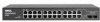
PowerConnect 2724 Front Panel On the front panel there are numbered 1 to 24, top down and left side of a combo port can switch from the RJ-45 to the SFP (or vice versa) without resetting the device. There are LEDs to right. The system automatically detects the media ...used on or not. The Power LED on the front panel indicates whether the device is the Managed Mode LED which indicates the Ethernet switch operational status. PowerConnect 2724 Back Panel 17 The two combo ports are logical ports with two physical connections: • An RJ-45 connection for Twisted Pair (TP) copper...
PowerConnect 2724 Front Panel On the front panel there are numbered 1 to 24, top down and left side of a combo port can switch from the RJ-45 to the SFP (or vice versa) without resetting the device. There are LEDs to right. The system automatically detects the media ...used on or not. The Power LED on the front panel indicates whether the device is the Managed Mode LED which indicates the Ethernet switch operational status. PowerConnect 2724 Back Panel 17 The two combo ports are logical ports with two physical connections: • An RJ-45 connection for Twisted Pair (TP) copper...

User's Guide
Page 18
... will be the active port, whereas the RJ-45 port will be used at any one of the two physical connections of a combo port can switch from the RJ-45 to the SFP (or vice versa) without resetting the device. A Managed Mode push-button, located on the far right side on... LED indicates the device fan operations status and the Power LED on the front panel, sets the device management mode. Figure 2-7. NOTE: Only one time. PowerConnect 2748 Back Panel 18 On each port, there are numbered 1 to 48, top down and left to indicate the port status. There are logical ports...
... will be the active port, whereas the RJ-45 port will be used at any one of the two physical connections of a combo port can switch from the RJ-45 to the SFP (or vice versa) without resetting the device. A Managed Mode push-button, located on the far right side on... LED indicates the device fan operations status and the Power LED on the front panel, sets the device management mode. Figure 2-7. NOTE: Only one time. PowerConnect 2748 Back Panel 18 On each port, there are numbered 1 to 48, top down and left to indicate the port status. There are logical ports...

User's Guide
Page 19
... Table 2-1. The following table describes the Power Supply status LED indications. Power LED On the PowerConnect 2708/2716/2724/2748 front panel there is a Managed Mode LED monitoring the switch node as well as indicating diagnostic test results. Power LED Indications LED Color Green Solid Off ... • Height - 43.2 mm (1.7008 in.) • Width - 256 mm (10.079 in.) • Depth - 161.7 mm (6.366 in.) The PowerConnect 2716 and PowerConnect 2724 switches have the following physical dimensions: • Height - 43.2 mm (1.7008 in.) • Width - 330 mm (12.992 in.) • Depth - 230...
... Table 2-1. The following table describes the Power Supply status LED indications. Power LED On the PowerConnect 2708/2716/2724/2748 front panel there is a Managed Mode LED monitoring the switch node as well as indicating diagnostic test results. Power LED Indications LED Color Green Solid Off ... • Height - 43.2 mm (1.7008 in.) • Width - 256 mm (10.079 in.) • Depth - 161.7 mm (6.366 in.) The PowerConnect 2716 and PowerConnect 2724 switches have the following physical dimensions: • Height - 43.2 mm (1.7008 in.) • Width - 330 mm (12.992 in.) • Depth - 230...

User's Guide
Page 20
Indicates the switch is in progress, firmware loading, or Managed Mode transition. No valid image. Indicates Unmanaged mode or Secure mode (2748 only). Fan LED Indications LED Color ... and the duplex mode is a fan LED. The following table: 20 Figure 2-9. One or more fans have failed. Table 2-2. Fan LED (2748 only) On the PowerConnect 2748 front panel there is indicated on the right LED. Diagnostics has failed. Port LEDs 10/100/1000BASE-T Port LEDs Each 10/100/1000BASE-T port...
Indicates the switch is in progress, firmware loading, or Managed Mode transition. No valid image. Indicates Unmanaged mode or Secure mode (2748 only). Fan LED Indications LED Color ... and the duplex mode is a fan LED. The following table: 20 Figure 2-9. One or more fans have failed. Table 2-2. Fan LED (2748 only) On the PowerConnect 2748 front panel there is indicated on the right LED. Diagnostics has failed. Port LEDs 10/100/1000BASE-T Port LEDs Each 10/100/1000BASE-T port...

User's Guide
Page 21
The port is linked at 1000 Mbps. The port is currently transmitting in Half Duplex mode. Managed Mode Button The PowerConnect 2708/2716/2724/2748 has a Managed Mode push button on the front panel. The port is currently not operating The port is operating in Full Duplex mode. ...LED Color Description Green Static Link is linked at 10 or 100 Mbps. After a change from Unmanaged (or Secure) Mode to Managed Mode, the switch restores the configuration values to Admin, and the password is not configured (appears blank), with Read/Write privilege. • The DHCP client is set...
The port is linked at 1000 Mbps. The port is currently transmitting in Half Duplex mode. Managed Mode Button The PowerConnect 2708/2716/2724/2748 has a Managed Mode push button on the front panel. The port is currently not operating The port is operating in Full Duplex mode. ...LED Color Description Green Static Link is linked at 10 or 100 Mbps. After a change from Unmanaged (or Secure) Mode to Managed Mode, the switch restores the configuration values to Admin, and the password is not configured (appears blank), with Read/Write privilege. • The DHCP client is set...

User's Guide
Page 22
.../100/1000BASE-T ports are supported. RJ-45 Connections for 100BASE-TX connections also operate with the IEEE 802.3ab standards. Switch Ventilation Fan The PowerConnect 2748 switch has three fans and the PowerConnect 2724 switch has one fan for the 10/100/1000BASE-T ports is listed in the following figure illustrates the RJ-45 pin connector...
.../100/1000BASE-T ports are supported. RJ-45 Connections for 100BASE-TX connections also operate with the IEEE 802.3ab standards. Switch Ventilation Fan The PowerConnect 2748 switch has three fans and the PowerConnect 2724 switch has one fan for the 10/100/1000BASE-T ports is listed in the following figure illustrates the RJ-45 pin connector...

User's Guide
Page 23
...ignored. 23 The optical transceiver provides access to the SFP (or vice versa) without a system reset. PowerConnect 2724 switch supports SFP diagnostics. The system can switch from the RJ-45 to a set of a combo port can be monitored and displayed to the system... administrator. SFP Ports The PowerConnect 2724 switch supports two SFP transceivers combo ports, and the PowerConnect 2748 switch supports four SFP transceivers combo ports for 10/100/ 1000BASE-T Ethernet Port Pin No Function 1 TxRx 1+ 2 TxRx 1-...
...ignored. 23 The optical transceiver provides access to the SFP (or vice versa) without a system reset. PowerConnect 2724 switch supports SFP diagnostics. The system can switch from the RJ-45 to a set of a combo port can be monitored and displayed to the system... administrator. SFP Ports The PowerConnect 2724 switch supports two SFP transceivers combo ports, and the PowerConnect 2748 switch supports four SFP transceivers combo ports for 10/100/ 1000BASE-T Ethernet Port Pin No Function 1 TxRx 1+ 2 TxRx 1-...

User's Guide
Page 24
... 19 Transmitter inverted data in 20 Transmitter ground (common with receiver ground) Power Connectors The PowerConnect 2708/2716/2724/2748 switches are powered by using the AC internal power supply. Internal Power Supply Connector The PowerConnect 2708, PowerConnect 2716, PowerConnect 2724 and PowerConnect 2748 switch systems supports a single internal power supply to provide power for SFP Interfaces Table 2-8. Pin...
... 19 Transmitter inverted data in 20 Transmitter ground (common with receiver ground) Power Connectors The PowerConnect 2708/2716/2724/2748 switches are powered by using the AC internal power supply. Internal Power Supply Connector The PowerConnect 2708, PowerConnect 2716, PowerConnect 2724 and PowerConnect 2748 switch systems supports a single internal power supply to provide power for SFP Interfaces Table 2-8. Pin...


