
User's Guide
Page 9
Multicast Forwarding Support 280 Defining IGMP Snooping Settings 281 Adding Bridge Multicast Group Members 284 Assigning Multicast Forward All Parameters 287 Enabling IGMP Snooping 289 8 Viewing Statistics Viewing ...
Multicast Forwarding Support 280 Defining IGMP Snooping Settings 281 Adding Bridge Multicast Group Members 284 Assigning Multicast Forward All Parameters 287 Enabling IGMP Snooping 289 8 Viewing Statistics Viewing ...
User's Guide
Page 10
... UDP Port Values to Queues 353 10 Getting Help Technical Assistance 358 Online Services 358 AutoTech Service 359 Automated Order-Status Service 359 Technical Support Service 360 Dell Enterprise Training and Certification 360 Problems With Your Order 360 Product Information 360 Returning Items for Warranty Repair or Credit 360 Before You Call...
... UDP Port Values to Queues 353 10 Getting Help Technical Assistance 358 Online Services 358 AutoTech Service 359 Automated Order-Status Service 359 Technical Support Service 360 Dell Enterprise Training and Certification 360 Problems With Your Order 360 Product Information 360 Returning Items for Warranty Repair or Credit 360 Before You Call...

User's Guide
Page 12
... per stack or scale up to 192 FE and six Gigabit Ethernet ports. www.dell.com | support.dell.com System Description The Dell™ PowerConnect™ 3324 and 3348 devices are accessed through a single IP address for SNMP management and a console/telnet session through a single point as stand-alone Layer 2 switching systems. PowerConnect 3324/3348 devices are a single unit.
... per stack or scale up to 192 FE and six Gigabit Ethernet ports. www.dell.com | support.dell.com System Description The Dell™ PowerConnect™ 3324 and 3348 devices are accessed through a single IP address for SNMP management and a console/telnet session through a single point as stand-alone Layer 2 switching systems. PowerConnect 3324/3348 devices are a single unit.

User's Guide
Page 14
...the stack configuration. Configuration files are displayed in the Dell OpenManage™ Switch Administrator and can be configured through the web management system. If a PowerConnect 3324/3348 stack member is removed from an external TFTP Server. ...dell.com | support.dell.com When the master unit boots or when inserting or removing a stack member, the master unit initiates a stacking discover process. In addition, Configuration files are not automatically modified when: • Units are added. • Units are removed. • Units are managed only from the PowerConnect 3324/3348...
...the stack configuration. Configuration files are displayed in the Dell OpenManage™ Switch Administrator and can be configured through the web management system. If a PowerConnect 3324/3348 stack member is removed from an external TFTP Server. ...dell.com | support.dell.com When the master unit boots or when inserting or removing a stack member, the master unit initiates a stacking discover process. In addition, Configuration files are not automatically modified when: • Units are added. • Units are removed. • Units are managed only from the PowerConnect 3324/3348...

User's Guide
Page 16
... device's G1 and G2 port configuration. • If a PowerConnect 3348 replaces PowerConnect 3324, then ports 1-24 10/100 BaseT receive the previous device's configuration for ports 1-24. • Ports 25-48 receive the factory default port configuration. www.dell.com | support.dell.com PowerConnect 3324 Replaces PowerConnect 3348 • If a PowerConnect 3348 replaces PowerConnect 3348, the new 48 10/100 BaseT ports receive...
... device's G1 and G2 port configuration. • If a PowerConnect 3348 replaces PowerConnect 3324, then ports 1-24 10/100 BaseT receive the previous device's configuration for ports 1-24. • Ports 25-48 receive the factory default port configuration. www.dell.com | support.dell.com PowerConnect 3324 Replaces PowerConnect 3348 • If a PowerConnect 3348 replaces PowerConnect 3348, the new 48 10/100 BaseT ports receive...

User's Guide
Page 17
...PowerConnect 3324/3348 Switch-Contains instructions about installing PowerConnect 3324/3348 in either a rack or on a flat surface. PowerConnect User Guide Overview The PowerConnect User Guide is divided into two parts: • About Installing the PowerConnect 3324/3348 Switch • Using the Dell OpenManage Switch Administrator Installing the PowerConnect 3324/3348 Switch... SNMP communities, downloading the device software, and defining advanced settings. • Configuring Switch Information-Contains information about configuring port and VLANs, defining both static and dynamic address ...
...PowerConnect 3324/3348 Switch-Contains instructions about installing PowerConnect 3324/3348 in either a rack or on a flat surface. PowerConnect User Guide Overview The PowerConnect User Guide is divided into two parts: • About Installing the PowerConnect 3324/3348 Switch • Using the Dell OpenManage Switch Administrator Installing the PowerConnect 3324/3348 Switch... SNMP communities, downloading the device software, and defining advanced settings. • Configuring Switch Information-Contains information about configuring port and VLANs, defining both static and dynamic address ...

User's Guide
Page 18
... information about technical assistance, problems with your order, returning items for repair or credit, and how to contact Dell. PowerConnect 3324/3348 CLI Documentation In addition to configure the PowerConnect 3324/3348. 18 Over view www.dell.com | support.dell.com • Configuring Quality of Service-Contains information about configuring device Class of Service. • Getting Help-Contains...
... information about technical assistance, problems with your order, returning items for repair or credit, and how to contact Dell. PowerConnect 3324/3348 CLI Documentation In addition to configure the PowerConnect 3324/3348. 18 Over view www.dell.com | support.dell.com • Configuring Quality of Service-Contains information about configuring device Class of Service. • Getting Help-Contains...

User's Guide
Page 20
DC Console Port RPS Connector Power Connector PowerConnect 3348 Rear Panel PowerConnect 3324/3348 Components This section describes different PowerConnect 3324/3348 hardware components, and includes the following figure: PowerConnect 3324 Rear Panel RPS - DC RPS Connector Power Connector RPS - www.dell.com | support.dell.com PowerConnect 3324/3348 Description PowerConnect 3324/3348 Dimensions This device has the following dimensions: • Width-19" • Height...
DC Console Port RPS Connector Power Connector PowerConnect 3348 Rear Panel PowerConnect 3324/3348 Components This section describes different PowerConnect 3324/3348 hardware components, and includes the following figure: PowerConnect 3324 Rear Panel RPS - DC RPS Connector Power Connector RPS - www.dell.com | support.dell.com PowerConnect 3324/3348 Description PowerConnect 3324/3348 Dimensions This device has the following dimensions: • Width-19" • Height...

User's Guide
Page 22
...4. This completes the Ring Topology. Once the Stack Master is selected, the remaining devices are connected to port G2. Stacking Modules and Connectors PowerConnect 3324/3348 Stacking modules are defined as stack members. For example, if there are 4 units in a stack, the Master unit is 1, the second...top unit's RX is the upper connection point. The module is not selected within 15 seconds after booting the device. www.dell.com | support.dell.com Mode Button The Mode Button toggles between port activity and port duplex settings. Stack members receive a separate Unit ID (2-6).
...4. This completes the Ring Topology. Once the Stack Master is selected, the remaining devices are connected to port G2. Stacking Modules and Connectors PowerConnect 3324/3348 Stacking modules are defined as stack members. For example, if there are 4 units in a stack, the Master unit is 1, the second...top unit's RX is the upper connection point. The module is not selected within 15 seconds after booting the device. www.dell.com | support.dell.com Mode Button The Mode Button toggles between port activity and port duplex settings. Stack members receive a separate Unit ID (2-6).

User's Guide
Page 24
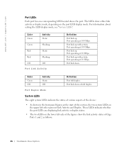
www.dell.com | support.dell.com Ports Description Ethernet Port Description The PowerConnect 3324 features 24 FE 10BaseT/100BaseTX UTP copper RJ45 ports per unit and 2 combo ports. If auto-MDIX is a single logical port that has the ... at any one stop bit, and no parity. The LED types are supported (9 pins) for copper ports. Each combo port is enabled, PowerConnect 3324/3348 automatically detects and corrects the difference between crossover and straight-through cables on all ports. The PowerConnect 3348 features 48 FE 10BaseT/100BaseTX UTP copper RJ45 ports per unit and...
www.dell.com | support.dell.com Ports Description Ethernet Port Description The PowerConnect 3324 features 24 FE 10BaseT/100BaseTX UTP copper RJ45 ports per unit and 2 combo ports. If auto-MDIX is a single logical port that has the ... at any one stop bit, and no parity. The LED types are supported (9 pins) for copper ports. Each combo port is enabled, PowerConnect 3324/3348 automatically detects and corrects the difference between crossover and straight-through cables on all ports. The PowerConnect 3348 features 48 FE 10BaseT/100BaseTX UTP copper RJ45 ports per unit and...
User's Guide
Page 26
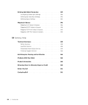
For information about setting the LED display mode, see "System LEDs". Port link up with activity. Port operating at 10 Mbps. Port link down . www.dell.com | support.dell.com Port LEDs Each port has one corresponding LED located above the port. The LEDs show either link activity or duplex mode, depending on the...
For information about setting the LED display mode, see "System LEDs". Port link up with activity. Port operating at 10 Mbps. Port link down . www.dell.com | support.dell.com Port LEDs Each port has one corresponding LED located above the port. The LEDs show either link activity or duplex mode, depending on the...
User's Guide
Page 28
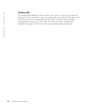
www.dell.com | support.dell.com Stacking LEDs The stacking LEDs indicate the unit's position in the stack. When one stacking LED lit, indicating its position in the stack. Each unit in the stack has one of this section, the stacking LEDs are numbered 1 through 6 is lit, the unit is the master unit. When stacking LED 1 is lit, the unit is the corresponding stacking member unit. 28 H a r d w a r e D e s c r i p t i o n As shown in the front panel illustrations at the start of the stacking LEDs numbered 2 through 6.
www.dell.com | support.dell.com Stacking LEDs The stacking LEDs indicate the unit's position in the stack. When one stacking LED lit, indicating its position in the stack. Each unit in the stack has one of this section, the stacking LEDs are numbered 1 through 6 is lit, the unit is the master unit. When stacking LED 1 is lit, the unit is the corresponding stacking member unit. 28 H a r d w a r e D e s c r i p t i o n As shown in the front panel illustrations at the start of the stacking LEDs numbered 2 through 6.

User's Guide
Page 30
... with approved equipment. The maximum ampere ratings are not blocked. Site Requirements Dell™ PowerConnect™ 3324/3348 series equipment can be serviced by trained service technicians only. www.dell.com | support.dell.com Installation Precautions CAUTION: The rack or cabinet housing the switch should be adequately secured to prevent it may cause electrical shock. CAUTION: Ensure...
... with approved equipment. The maximum ampere ratings are not blocked. Site Requirements Dell™ PowerConnect™ 3324/3348 series equipment can be serviced by trained service technicians only. www.dell.com | support.dell.com Installation Precautions CAUTION: The rack or cabinet housing the switch should be adequately secured to prevent it may cause electrical shock. CAUTION: Ensure...

User's Guide
Page 32
... pair of screws to a metal surface. 2 Place the PowerConnect 3324/3348 switch on a flat and stable surface. 3 Place the supplied rack-mounting bracket on n e c t 3324/3348 Sw itc h Report any damage immediately. For information about contacting Dell, see "Getting Help". The surface must be able to support the weight of the device and the device cables...
... pair of screws to a metal surface. 2 Place the PowerConnect 3324/3348 switch on a flat and stable surface. 3 Place the supplied rack-mounting bracket on n e c t 3324/3348 Sw itc h Report any damage immediately. For information about contacting Dell, see "Getting Help". The surface must be able to support the weight of the device and the device cables...

User's Guide
Page 33
.... 4 Connect the stack in the rack or on a flat surface. 2 Insert a stacking connector for each G2 port. Installing the PowerConnect 3324/3348 Switch 33 To enable stacking, units must be included in the SFP slot. Connecting Stacking Cables 1 Place each device in a stacking ring topology... units are connected via a stacking cable. All management is not completed, the stack does not function. Stacking PowerConnect 3324/3348 PowerConnect 3324/3348 supports stacking up to six PowerConnect 3324/3348 devices or up to port G2 in the stack. Both 24-port and 48-port devices can be stacked ...
.... 4 Connect the stack in the rack or on a flat surface. 2 Insert a stacking connector for each G2 port. Installing the PowerConnect 3324/3348 Switch 33 To enable stacking, units must be included in the SFP slot. Connecting Stacking Cables 1 Place each device in a stacking ring topology... units are connected via a stacking cable. All management is not completed, the stack does not function. Stacking PowerConnect 3324/3348 PowerConnect 3324/3348 supports stacking up to six PowerConnect 3324/3348 devices or up to port G2 in the stack. Both 24-port and 48-port devices can be stacked ...
User's Guide
Page 34
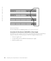
The PowerConnect 3324/3348 is supplied with power from: • AC power supply source. • An optional PowerConnect RPS-600 redundant power supply. • Both AC and DC sources. 34 I n s t a llin g t h e Po we rC on configuring stacks, see "Configuring Stacking". Connecting the PowerConnect 3324/3348 to a Power Supply The following section contains instruction for connecting the PowerConnect 3324/3348 to a AC power connection. www.dell.com | support.dell.com Connected Stack For more information on n e c t 3324/3348 Sw itc h
The PowerConnect 3324/3348 is supplied with power from: • AC power supply source. • An optional PowerConnect RPS-600 redundant power supply. • Both AC and DC sources. 34 I n s t a llin g t h e Po we rC on configuring stacks, see "Configuring Stacking". Connecting the PowerConnect 3324/3348 to a Power Supply The following section contains instruction for connecting the PowerConnect 3324/3348 to a AC power connection. www.dell.com | support.dell.com Connected Stack For more information on n e c t 3324/3348 Sw itc h

User's Guide
Page 36
www.dell.com | support.dell.com Port Connections The ports are all standard RJ45 Ethernet ports. RJ45 Pin Number Allocation Pin Use 1 RX + 2 RX 3 TX + 4 5 -6 TX 78- 36 I n s t a llin g t h e Po we rC on n e c t 3324/3348 Sw itc h Switching ports can connect to each other. Transmission devices use crossed cables to connect to stations wired in standard RJ45 Ethernet station mode using straight cables. The following figure illustrates the RJ45 pin number allocations for the 10/100M ports.
www.dell.com | support.dell.com Port Connections The ports are all standard RJ45 Ethernet ports. RJ45 Pin Number Allocation Pin Use 1 RX + 2 RX 3 TX + 4 5 -6 TX 78- 36 I n s t a llin g t h e Po we rC on n e c t 3324/3348 Sw itc h Switching ports can connect to each other. Transmission devices use crossed cables to connect to stations wired in standard RJ45 Ethernet station mode using straight cables. The following figure illustrates the RJ45 pin number allocations for the 10/100M ports.
User's Guide
Page 38
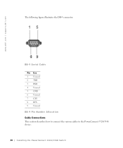
www.dell.com | support.dell.com The following figure illustrates the DB-9 connector. DB-9 Serial Cable Pin Use 1 Unused 2 TXD 3 RXD 4 Unused 5 GND 6 Unused 7 CTS 8 RTS 9 Unused DB-9 Pin Number Allocation Cable Connections This section describes how to connect the various cables to the PowerConnect 3324/3348 device. 38 I n s t a llin g t h e Po we rC on n e c t 3324/3348 Sw itc h
www.dell.com | support.dell.com The following figure illustrates the DB-9 connector. DB-9 Serial Cable Pin Use 1 Unused 2 TXD 3 RXD 4 Unused 5 GND 6 Unused 7 CTS 8 RTS 9 Unused DB-9 Pin Number Allocation Cable Connections This section describes how to connect the various cables to the PowerConnect 3324/3348 device. 38 I n s t a llin g t h e Po we rC on n e c t 3324/3348 Sw itc h
User's Guide
Page 40
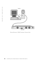
www.dell.com | support.dell.com PowerConnect 3348 Terminal Connection 40 I n s t a llin g t h e Po we rC on n e c t 3324/3348 Sw itc h
www.dell.com | support.dell.com PowerConnect 3348 Terminal Connection 40 I n s t a llin g t h e Po we rC on n e c t 3324/3348 Sw itc h

User's Guide
Page 42
The order of installation and configuration procedures are in the following flowchart: 42 C o n f i g u r i n g t h e Po w e r C o n n e c t 3 3 2 4 / 3 3 4 8 S w i t c h www.dell.com | support.dell.com Configuration Overview This section describes the initial device configuration and includes: • Initial Device Bootup • Preliminary Configuration Requirements • Configuring Stacking After all the device external connections are illustrated in place, a terminal must be connected to the device to monitor the boot and other procedures.
The order of installation and configuration procedures are in the following flowchart: 42 C o n f i g u r i n g t h e Po w e r C o n n e c t 3 3 2 4 / 3 3 4 8 S w i t c h www.dell.com | support.dell.com Configuration Overview This section describes the initial device configuration and includes: • Initial Device Bootup • Preliminary Configuration Requirements • Configuring Stacking After all the device external connections are illustrated in place, a terminal must be connected to the device to monitor the boot and other procedures.


