
Alienware Desktop Manual
Page 2
... manner whatsoever without notice. © 2009 Dell Inc. and is strictly prohibited. Notes, Cautions, and Warnings NOTE: A NOTE indicates important information that helps you how to avoid the problem. is used in this manual: Alienware, AlienRespawn, AlienFX, and the AlienHead logo are... either potential damage to hardware or loss of Dell Inc. Model: D0IX Type: D0IX001 P/N: K830R Rev:A00 August 2009 02 /02...
... manner whatsoever without notice. © 2009 Dell Inc. and is strictly prohibited. Notes, Cautions, and Warnings NOTE: A NOTE indicates important information that helps you how to avoid the problem. is used in this manual: Alienware, AlienRespawn, AlienFX, and the AlienHead logo are... either potential damage to hardware or loss of Dell Inc. Model: D0IX Type: D0IX001 P/N: K830R Rev:A00 August 2009 02 /02...

Alienware Desktop Manual
Page 14
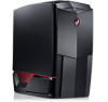
...illuminates indicating that the computer is not receiving power. • Solid white - Ejects the optical drive tray. 014 /014 Press the Alienhead and then manually lower or close the drive panel using the motorized door. 4 When the computer is turned off when pressed. the computer is either turned off, ...2 Optical drive - Front View Features 1 2 3 CHAPTER 2: GETTING TO KNOW YOUR DESKTOP 1 Power button - Turns the computer on . Supports additional optical drive(s) (optional). 4 Alienhead • Area-51 Standard - Press the Alienhead to lower or close the drive panel. 5 •...
...illuminates indicating that the computer is not receiving power. • Solid white - Ejects the optical drive tray. 014 /014 Press the Alienhead and then manually lower or close the drive panel using the motorized door. 4 When the computer is turned off when pressed. the computer is either turned off, ...2 Optical drive - Front View Features 1 2 3 CHAPTER 2: GETTING TO KNOW YOUR DESKTOP 1 Power button - Turns the computer on . Supports additional optical drive(s) (optional). 4 Alienhead • Area-51 Standard - Press the Alienhead to lower or close the drive panel. 5 •...

Alienware Desktop Manual
Page 29
NOTE: For the updated system setup information, see the Service Manual at support.dell.com/manuals. Memory Available Displays the amount of memory available in your computer. Memory Speed Displays the memory speed. CHAPTER 4: USING YOUR DESKTOP System Information Memory Installed ...
NOTE: For the updated system setup information, see the Service Manual at support.dell.com/manuals. Memory Available Displays the amount of memory available in your computer. Memory Speed Displays the memory speed. CHAPTER 4: USING YOUR DESKTOP System Information Memory Installed ...

Alienware Desktop Manual
Page 33
...timing of processor. Overclock Configuration Submenu Adjust CPU BClk (MHz) Allows you to program the current thresholds for the processor while in Manual Mode). Advance DRAM Configuration Submenu Memory-Z Opens submenu to display the SPD configuration for cores 1-4. tRCD Displays timing of RAS to ...CAS delay (editable in Manual Mode). tRRD Displays RAS to run at faster frequencies than marked. [1-4] Core CPU Turbo Ratio Limit Limit ratio for each memory ...
...timing of processor. Overclock Configuration Submenu Adjust CPU BClk (MHz) Allows you to program the current thresholds for the processor while in Manual Mode). Advance DRAM Configuration Submenu Memory-Z Opens submenu to display the SPD configuration for cores 1-4. tRCD Displays timing of RAS to ...CAS delay (editable in Manual Mode). tRRD Displays RAS to run at faster frequencies than marked. [1-4] Core CPU Turbo Ratio Limit Limit ratio for each memory ...

Alienware Desktop Manual
Page 35
... REPLACEMENT COMPONENTS CHAPTER 5: INSTALLING ADDITIONAL OR REPLACEMENT COMPONENTS CHAPTER 5: INSTALLING ADDITIONAL OR REPLACEMENT COMPONENTS This chapter provides guidelines and instructions for your desktop at support.dell.com/manuals for installation instructions of all serviceable components. Parts purchased from Dell and Alienware ship with specific replacement instructions. 035 /035 NOTE: See the Service...
... REPLACEMENT COMPONENTS CHAPTER 5: INSTALLING ADDITIONAL OR REPLACEMENT COMPONENTS CHAPTER 5: INSTALLING ADDITIONAL OR REPLACEMENT COMPONENTS This chapter provides guidelines and instructions for your desktop at support.dell.com/manuals for installation instructions of all serviceable components. Parts purchased from Dell and Alienware ship with specific replacement instructions. 035 /035 NOTE: See the Service...

Alienware Desktop Manual
Page 50
...; Shut down your computer, disconnect the power cable, and open your computer. For additional safety best practices information, see the Regulatory Compliance Homepage at www.dell.com/regulatory_compliance. Make sure that the SATA controllers are enabled. CHAPTER 6: TROUBLESHOOTING Answers to Common Problems CD-ROM, DVD-ROM, CD-R/W, DVD±R/W, or Blu... to ensure that the cables are properly connected to the drive and the SATA connector on your system board or controller card (see the Service Manual). 050 /050 Check the drive configuration to make sure it is properly configured;
...; Shut down your computer, disconnect the power cable, and open your computer. For additional safety best practices information, see the Regulatory Compliance Homepage at www.dell.com/regulatory_compliance. Make sure that the SATA controllers are enabled. CHAPTER 6: TROUBLESHOOTING Answers to Common Problems CD-ROM, DVD-ROM, CD-R/W, DVD±R/W, or Blu... to ensure that the cables are properly connected to the drive and the SATA connector on your system board or controller card (see the Service Manual). 050 /050 Check the drive configuration to make sure it is properly configured;

Alienware Desktop Manual
Page 51
...memory module is seated properly. NOTE: To replace parts, see "CONTACTING ALIENWARE" on your keyboard or moving your mouse, press and hold the power button for details, see the Service Manual at least 6 seconds until the computer turns off, then restart your ...computer. Click End Task. If necessary, uninstall and then reinstall the program. 051 /051 For assistance, contact Alienware (for at support.dell.com/manuals. Possible motherboard failure - Check the software documentation. Press simultaneously. 2. If the computer passes the POST, the computer will...
...memory module is seated properly. NOTE: To replace parts, see "CONTACTING ALIENWARE" on your keyboard or moving your mouse, press and hold the power button for details, see the Service Manual at least 6 seconds until the computer turns off, then restart your ...computer. Click End Task. If necessary, uninstall and then reinstall the program. 051 /051 For assistance, contact Alienware (for at support.dell.com/manuals. Possible motherboard failure - Check the software documentation. Press simultaneously. 2. If the computer passes the POST, the computer will...

Alienware Desktop Manual
Page 64
For more detailed specifications, see the Comprehensive Specifications at support.dell.com/manuals. 064 /064 CHAPTER 8: BASIC SPECIFICATIONS CHAPTER 8: BASIC SPECIFICATIONS CHAPTER 8: BASIC SPECIFICATIONS This chapter provides the basic specifications of your desktop.
For more detailed specifications, see the Comprehensive Specifications at support.dell.com/manuals. 064 /064 CHAPTER 8: BASIC SPECIFICATIONS CHAPTER 8: BASIC SPECIFICATIONS CHAPTER 8: BASIC SPECIFICATIONS This chapter provides the basic specifications of your desktop.

Comprehensive Specifications
Page 2
... countries; Other trademarks and trade names may be used in this manual to refer to change without the prior written permission of Dell Inc. Trademarks used by Bluetooth SIG, Inc. Intel is a registered trademark and Core is used in this manual: Alienware and AlienFX are subject to either the entities claiming the marks and...
... countries; Other trademarks and trade names may be used in this manual to refer to change without the prior written permission of Dell Inc. Trademarks used by Bluetooth SIG, Inc. Intel is a registered trademark and Core is used in this manual: Alienware and AlienFX are subject to either the entities claiming the marks and...

Comprehensive Specifications
Page 5
... 164-pin connector Number of lanes PCI_E1 PCI_E3 16 16 16 8 PCI_E5 4 8 NOTE: For the location of the PCI Express x16 connectors, see the Service Manual at support.dell.com/manuals. 05 /05
... 164-pin connector Number of lanes PCI_E1 PCI_E3 16 16 16 8 PCI_E5 4 8 NOTE: For the location of the PCI Express x16 connectors, see the Service Manual at support.dell.com/manuals. 05 /05

Service Manual
Page 2
...and trade names may be used by Bluetooth SIG, Inc. Dell Inc. Reproduction of Dell Inc. WARNING: A WARNING indicates a potential for property damage, personal injury, or death. and is used in this manual: Alienware is a trademark of Intel Corporation in the U.S. disclaims ...any manner whatsoever without notice. © 2009 Dell Inc. Notes, Cautions, and Warnings NOTE: A NOTE indicates important information...
...and trade names may be used by Bluetooth SIG, Inc. Dell Inc. Reproduction of Dell Inc. WARNING: A WARNING indicates a potential for property damage, personal injury, or death. and is used in this manual: Alienware is a trademark of Intel Corporation in the U.S. disclaims ...any manner whatsoever without notice. © 2009 Dell Inc. Notes, Cautions, and Warnings NOTE: A NOTE indicates important information...
Service Manual
Page 6
...-if purchased separately-installed by performing the removal procedure in your computer. CHAPTER 1: BEFORE YOU BEGIN CHAPTER 1: BEFORE YOU BEGIN CHAPTER 1: BEFORE YOU BEGIN This manual provides procedures for removing and installing the components in reverse order. 06 /06
...-if purchased separately-installed by performing the removal procedure in your computer. CHAPTER 1: BEFORE YOU BEGIN CHAPTER 1: BEFORE YOU BEGIN CHAPTER 1: BEFORE YOU BEGIN This manual provides procedures for removing and installing the components in reverse order. 06 /06
Service Manual
Page 24
See the specifications in your Desktop Manual or in the Comprehensive Specifications at support.dell.com for information on the system board. NOTE: Memory modules purchased from Dell or Alienware are supported by your computer. Your computer has three internally-accessible DDR3 DIMM sockets. 024 /024 Install only memory modules that are covered under your computer memory by installing memory modules on the memory supported by your computer. CHAPTER 5: MEMORY MODULE(S) CHAPTER 5: MEMORY MODULE(S) CHAPTER 5: MEMORY MODULE(S) You can increase your computer warranty.
See the specifications in your Desktop Manual or in the Comprehensive Specifications at support.dell.com for information on the system board. NOTE: Memory modules purchased from Dell or Alienware are supported by your computer. Your computer has three internally-accessible DDR3 DIMM sockets. 024 /024 Install only memory modules that are covered under your computer memory by installing memory modules on the memory supported by your computer. CHAPTER 5: MEMORY MODULE(S) CHAPTER 5: MEMORY MODULE(S) CHAPTER 5: MEMORY MODULE(S) You can increase your computer warranty.
Service Manual
Page 80
...with your warranty. CHAPTER 16: SYSTEM BOARD 080 /080 CAUTION: Only a certified service technician should perform repairs on contacting Dell, see the Regulatory Compliance Homepage at www.dell.com/regulatory_compliance. CAUTION: To avoid electrostatic discharge, ground yourself by using a wrist grounding strap or by your computer. WARNING:...(s) (including side panels, bezels, filler brackets, front-panel inserts, etc.) removed. Performing these steps incorrectly could damage your Desktop Manual. For additional safety best practices information, see your system board.
...with your warranty. CHAPTER 16: SYSTEM BOARD 080 /080 CAUTION: Only a certified service technician should perform repairs on contacting Dell, see the Regulatory Compliance Homepage at www.dell.com/regulatory_compliance. CAUTION: To avoid electrostatic discharge, ground yourself by using a wrist grounding strap or by your computer. WARNING:...(s) (including side panels, bezels, filler brackets, front-panel inserts, etc.) removed. Performing these steps incorrectly could damage your Desktop Manual. For additional safety best practices information, see your system board.

Service Manual
Page 99
... Memory Settings Allows you to Manual mode and set all of Row Address Strobe (editable in Manual Mode). tRFC Displays timing of Write Recover (editable in Manual Mode). tWTR Displays Write to Archive/ Refresh cycle time (editable in Manual Mode). tCL Displays the Column... for each memory module. CHAPTER 19: SYSTEM SETUP Advance DRAM Configuration Submenu Memory-Z Opens submenu to CAS delay (editable in Manual Mode). Frequency/Voltage Control CPU Core (Non-Turbo) Ratio Advance DRAM Configuration Overclock Configuration Overvoltage Configuration Load Level 1 OC Setting...
... Memory Settings Allows you to Manual mode and set all of Row Address Strobe (editable in Manual Mode). tRFC Displays timing of Write Recover (editable in Manual Mode). tWTR Displays Write to Archive/ Refresh cycle time (editable in Manual Mode). tCL Displays the Column... for each memory module. CHAPTER 19: SYSTEM SETUP Advance DRAM Configuration Submenu Memory-Z Opens submenu to CAS delay (editable in Manual Mode). Frequency/Voltage Control CPU Core (Non-Turbo) Ratio Advance DRAM Configuration Overclock Configuration Overvoltage Configuration Load Level 1 OC Setting...

Service Manual
Page 100
tRTP Displays Read to adjust PCI Frequency. Adjust PCI-E Frequency (MHz) Allows you to Precharge Command Delay (editable in Manual Mode). 1T/2T Timing Displays the Command Rate (editable in turbo mode. Displays processor core voltage. Spread Spectrum Enable/Disable Spread... DDR3 memory voltage. Intel® Turbo Mode tech If enabled, allows processor to program the power thresholds for the processor while in Manual Mode). Overvoltage Configuration Submenu CPU Temperature Sensor VCore Dynamic CPU VCore Offset DDR3 Memory Voltage IOH Voltage QPI and Uncore Voltage Displays the ...
tRTP Displays Read to adjust PCI Frequency. Adjust PCI-E Frequency (MHz) Allows you to Precharge Command Delay (editable in Manual Mode). 1T/2T Timing Displays the Command Rate (editable in turbo mode. Displays processor core voltage. Spread Spectrum Enable/Disable Spread... DDR3 memory voltage. Intel® Turbo Mode tech If enabled, allows processor to program the power thresholds for the processor while in Manual Mode). Overvoltage Configuration Submenu CPU Temperature Sensor VCore Dynamic CPU VCore Offset DDR3 Memory Voltage IOH Voltage QPI and Uncore Voltage Displays the ...

