
Quick Reference Guide
Page 31
... L I N E F A I L U R E - See your Service Manual at support.dell.com for more information. For external keyboards, check the cable connection. For external keyboards or keypads, check the cable connection. MEMORY ADDRESS LINE FAILURE AT ADDRESS, READ VALUE EXPECTING VALUE -...Dell™ MediaDirect™ cannot verify the Digital Rights Management (DRM) restrictions on the file, so the file cannot be defective. A memory module may be played (see your Service Manual at support.dell.com), and boot the computer from a CD. Reinstall the memory modules and, if necessary, replace...
... L I N E F A I L U R E - See your Service Manual at support.dell.com for more information. For external keyboards, check the cable connection. For external keyboards or keypads, check the cable connection. MEMORY ADDRESS LINE FAILURE AT ADDRESS, READ VALUE EXPECTING VALUE -...Dell™ MediaDirect™ cannot verify the Digital Rights Management (DRM) restrictions on the file, so the file cannot be defective. A memory module may be played (see your Service Manual at support.dell.com), and boot the computer from a CD. Reinstall the memory modules and, if necessary, replace...
Quick Reference Guide
Page 34
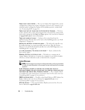
...Keyboard Controller test in the table, see "Contacting Dell" on the system board may require recharging. The battery is not listed in the Dell Diagnostics (see "Contacting Dell" on page 36). System Messages NOTE: If the message you received is running when the message appeared. D A Y N O T S E T - Replace...I S C R I T I B L E . CPU FAN FAILURE - Connect your Service Manual at support.dell.com or see "Dell Diagnostics" on page 61 for assistance). P L E A S E R U N T H E S YS T E M S E T U P P R O G R A M - Replace battery. U N E X P E C T E D I N T E R R U P T ...
...Keyboard Controller test in the table, see "Contacting Dell" on the system board may require recharging. The battery is not listed in the Dell Diagnostics (see "Contacting Dell" on page 36). System Messages NOTE: If the message you received is running when the message appeared. D A Y N O T S E T - Replace...I S C R I T I B L E . CPU FAN FAILURE - Connect your Service Manual at support.dell.com or see "Dell Diagnostics" on page 61 for assistance). P L E A S E R U N T H E S YS T E M S E T U P P R O G R A M - Replace battery. U N E X P E C T E D I N T E R R U P T ...

Technical Guide
Page 3
... my desk. End User Customer Viewpoint I 'm caught in a difficult place. Latitude™ E-Family Answer Dell is both rugged and beautiful. That can get more done and your notebooks and data. With Dell™ E5500 and E5400, you working anywhere, anytime. No detail went overlooked, inside or ...out. IT Customer Viewpoint I 'm sick of our workforce with a difficult-to-use keyboard or trackpad. My company data should be just as...
... my desk. End User Customer Viewpoint I 'm caught in a difficult place. Latitude™ E-Family Answer Dell is both rugged and beautiful. That can get more done and your notebooks and data. With Dell™ E5500 and E5400, you working anywhere, anytime. No detail went overlooked, inside or ...out. IT Customer Viewpoint I 'm sick of our workforce with a difficult-to-use keyboard or trackpad. My company data should be just as...

Service Manual
Page 16
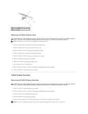
...procedures in Before Working on Your Computer. Follow the instructions in After Working on Your Computer. 2. Replace the keyboard (see Removing the Hinge Cover). 3. Remove the hinge cover (see Replacing the Keyboard). 8. E5400 Display Bezel Removing the E5400 Display Bezel CAUTION: Before you begin the following procedure, ... that shipped with your computer. Connect the antenna cables to separate the remainder of the bezel. Remove the keyboard (see Replacing the Hinge Cover). 9. Starting at : www.dell.com/regulatory_compliance. 1. Replace the hinge cover (see Removing the...
...procedures in Before Working on Your Computer. Follow the instructions in After Working on Your Computer. 2. Replace the keyboard (see Removing the Hinge Cover). 3. Remove the hinge cover (see Replacing the Keyboard). 8. E5400 Display Bezel Removing the E5400 Display Bezel CAUTION: Before you begin the following procedure, ... that shipped with your computer. Connect the antenna cables to separate the remainder of the bezel. Remove the keyboard (see Replacing the Hinge Cover). 9. Starting at : www.dell.com/regulatory_compliance. 1. Replace the hinge cover (see Removing the...

Service Manual
Page 17
.... NOTE: This procedure assumes that shipped with your computer. Remove the display assembly (see Replacing the Keyboard). 4. Starting at : www.dell.com/regulatory_compliance. Replace the keyboard (see Removing the E5400 Display Assembly). 5. Follow the instructions in After Working on www.dell.com at any corner, use your fingers to gently snap the bezel into place to...
.... NOTE: This procedure assumes that shipped with your computer. Remove the display assembly (see Replacing the Keyboard). 4. Starting at : www.dell.com/regulatory_compliance. Replace the keyboard (see Removing the E5400 Display Assembly). 5. Follow the instructions in After Working on www.dell.com at any corner, use your fingers to gently snap the bezel into place to...
Service Manual
Page 18
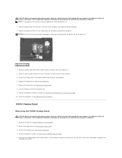
... 8. Disconnect the two display inverter connectors. 8. Replace the keyboard (see Replacing the E5400 Bottom of the base assembly (see Replacing the Keyboard). 5. Follow the procedures in Before Working on Your Computer. 2. Remove the hinge cover (see Replacing the E5500 Display Bezel). 3. Remove the M2.5 x 5-... panels are labeled L (left) and R (right). 2. Follow the instructions in After Working on www.dell.com at: www.dell.com/regulatory_compliance. E5400 Display Inverter Removing the E5400 Display Inverter CAUTION: Before you have completed the removal procedure first. 1.
... 8. Disconnect the two display inverter connectors. 8. Replace the keyboard (see Replacing the E5400 Bottom of the base assembly (see Replacing the Keyboard). 5. Follow the procedures in Before Working on Your Computer. 2. Remove the hinge cover (see Replacing the E5500 Display Bezel). 3. Remove the M2.5 x 5-... panels are labeled L (left) and R (right). 2. Follow the instructions in After Working on www.dell.com at: www.dell.com/regulatory_compliance. E5400 Display Inverter Removing the E5400 Display Inverter CAUTION: Before you have completed the removal procedure first. 1.
Service Manual
Page 19
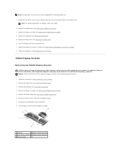
...dell.com/regulatory_compliance. 1. Connect the two display inverter connectors to the display inverter. 2. Replace the display bezel (see Removing the Hinge Cover). 3. For additional safety best practices information, see the Regulatory Compliance Homepage on each side of the Base Assembly). 9. Remove the hinge cover (see Replacing the E5400 Display Bezel). 4. Remove the keyboard...your computer. Remove the display bezel (see Removing the Keyboard). 4. Replace the bottom of the base assembly (see Replacing the Keyboard). 6. Follow the instructions in After Working on display...
...dell.com/regulatory_compliance. 1. Connect the two display inverter connectors to the display inverter. 2. Replace the display bezel (see Removing the Hinge Cover). 3. For additional safety best practices information, see the Regulatory Compliance Homepage on each side of the Base Assembly). 9. Remove the hinge cover (see Replacing the E5400 Display Bezel). 4. Remove the keyboard...your computer. Remove the display bezel (see Removing the Keyboard). 4. Replace the bottom of the base assembly (see Replacing the Keyboard). 6. Follow the instructions in After Working on display...

Service Manual
Page 20
... E5400 Display Inverter). 4. Position the display panel assembly in After Working on www.dell.com at : www.dell.com/regulatory_compliance. 1. Replace the display bezel (see Removing the Keyboard). 4. Replace the bottom of the base assembly (see the Regulatory Compliance Homepage on Your Computer. 2. Replace the eight M2 x 3-mm screws (four on the back of the top...
... E5400 Display Inverter). 4. Position the display panel assembly in After Working on www.dell.com at : www.dell.com/regulatory_compliance. 1. Replace the display bezel (see Removing the Keyboard). 4. Replace the bottom of the base assembly (see the Regulatory Compliance Homepage on Your Computer. 2. Replace the eight M2 x 3-mm screws (four on the back of the top...
Service Manual
Page 21
... Keyboard). 7. Replace the hinge cover (see Removing the E5400 Bottom of the Base Assembly). 3. Remove the bottom of the base assembly (see Replacing the Hinge Cover). 8. Remove the display cable from the system board by pulling on the blue tab next to the connector on www.dell.com at : www.dell.com/regulatory_compliance. Follow the...
... Keyboard). 7. Replace the hinge cover (see Removing the E5400 Bottom of the Base Assembly). 3. Remove the bottom of the base assembly (see Replacing the Hinge Cover). 8. Remove the display cable from the system board by pulling on the blue tab next to the connector on www.dell.com at : www.dell.com/regulatory_compliance. Follow the...
Service Manual
Page 23
... procedure first. 1. Follow the instructions in the base of the bezel. Replace the two pairs of M2.5 x 8-mm hinge screws on www.dell.com at: www.dell.com/regulatory_compliance. 1. Remove the keyboard (see Replacing the E5500 Bottom of the base assembly (see Removing the Keyboard). 4. Connect the display cable to separate the remainder of the computer, then...
... procedure first. 1. Follow the instructions in the base of the bezel. Replace the two pairs of M2.5 x 8-mm hinge screws on www.dell.com at: www.dell.com/regulatory_compliance. 1. Remove the keyboard (see Replacing the E5500 Bottom of the base assembly (see Removing the Keyboard). 4. Connect the display cable to separate the remainder of the computer, then...

Service Manual
Page 24
... the display and turn the computer over. 6. 1 display bezel NOTICE: Removal of the base assembly (see Replacing the Keyboard). 4. Replacing the E5500 Display Bezel CAUTION: Before you have completed the removal procedure first. 1. Starting at : www.dell.com/regulatory_compliance. Replace the hinge cover (see the Regulatory Compliance Homepage on Your Computer. Remove the display assembly (see...
... the display and turn the computer over. 6. 1 display bezel NOTICE: Removal of the base assembly (see Replacing the Keyboard). 4. Replacing the E5500 Display Bezel CAUTION: Before you have completed the removal procedure first. 1. Starting at : www.dell.com/regulatory_compliance. Replace the hinge cover (see the Regulatory Compliance Homepage on Your Computer. Remove the display assembly (see...

Service Manual
Page 25
... that shipped with your computer. E5500 Display Inverter Removing the E5500 Display Inverter CAUTION: Before you have completed the removal procedure first. 1. Remove the hinge cover (see Replacing the Keyboard). 5. Replace the keyboard (see Removing the Hinge Cover). 3. Follow the instructions in After Working on www.dell.com at : www.dell.com/regulatory_compliance. 1. Replace the four M2.5 x 8-mm screws...
... that shipped with your computer. E5500 Display Inverter Removing the E5500 Display Inverter CAUTION: Before you have completed the removal procedure first. 1. Remove the hinge cover (see Replacing the Keyboard). 5. Replace the keyboard (see Removing the Hinge Cover). 3. Follow the instructions in After Working on www.dell.com at : www.dell.com/regulatory_compliance. 1. Replace the four M2.5 x 8-mm screws...

Service Manual
Page 26
... shipped with your computer. Remove the hinge cover (see Replacing the Keyboard). 6. NOTE: This procedure assumes that secures the display inverter. 3. Follow the procedures in Before Working on www.dell.com at : www.dell.com/regulatory_compliance. 1. Lift the display inverter out of the top cover. 1 E5500 top cover 2 display connector 3 M2.5 x 5-mm screw 4 display inverter...
... shipped with your computer. Remove the hinge cover (see Replacing the Keyboard). 6. NOTE: This procedure assumes that secures the display inverter. 3. Follow the procedures in Before Working on www.dell.com at : www.dell.com/regulatory_compliance. 1. Lift the display inverter out of the top cover. 1 E5500 top cover 2 display connector 3 M2.5 x 5-mm screw 4 display inverter...

Service Manual
Page 27
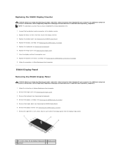
.... 1. Remove the hinge cover (see Replacing the E5500 Display Bezel). 4. Remove the keyboard (see Replacing the E5500 Bottom of the display panel) to secure the display panel to the display hinge panels. 2. For additional safety best practices information, see the Regulatory Compliance Homepage on www.dell.com at : www.dell.com/regulatory_compliance. 1. Replace the bottom of the display...
.... 1. Remove the hinge cover (see Replacing the E5500 Display Bezel). 4. Remove the keyboard (see Replacing the E5500 Bottom of the display panel) to secure the display panel to the display hinge panels. 2. For additional safety best practices information, see the Regulatory Compliance Homepage on www.dell.com at : www.dell.com/regulatory_compliance. 1. Replace the bottom of the display...

Service Manual
Page 28
... connector on www.dell.com at: www.dell.com/regulatory_compliance. Remove the display bezel (see Replacing the E5500 Display Panel). 3. Replace the display panel (see Removing the E5500 Display Bezel). 6. Back to the connector on Your Computer. Replace the display bezel (see Removing the E5500 Display Panel). 8. Remove the display panel (see Replacing the E5500 Display Bezel). 5. Replace the keyboard (see Replacing the Keyboard). 7.
... connector on www.dell.com at: www.dell.com/regulatory_compliance. Remove the display bezel (see Replacing the E5500 Display Panel). 3. Replace the display panel (see Removing the E5500 Display Bezel). 6. Back to the connector on Your Computer. Replace the display bezel (see Removing the E5500 Display Panel). 8. Remove the display panel (see Replacing the E5500 Display Bezel). 5. Replace the keyboard (see Replacing the Keyboard). 7.

Service Manual
Page 34
... Card Dell™ Latitude™ E5400 and E5500 Service Manual Removing an E5400 I/O Card Replacing an E5400 I/O Card Removing an E5500 I/O Card Replacing an E5500 I/O Card CAUTION: Before you begin any of the Base Assembly). 3. Follow the procedures in Before Working on www.dell.com at: www.dell.com/... processor heat sink (see Removing the E5400 System Board Assembly). 14. Remove the palm rest (see Removing the Keyboard). 9. The I /O Card 1. Remove the keyboard (see Removing the E5400 Palm Rest). 12. Removing an E5400 I /O card provides DC-in this section, ...
... Card Dell™ Latitude™ E5400 and E5500 Service Manual Removing an E5400 I/O Card Replacing an E5400 I/O Card Removing an E5500 I/O Card Replacing an E5500 I/O Card CAUTION: Before you begin any of the Base Assembly). 3. Follow the procedures in Before Working on www.dell.com at: www.dell.com/... processor heat sink (see Removing the E5400 System Board Assembly). 14. Remove the palm rest (see Removing the Keyboard). 9. The I /O Card 1. Remove the keyboard (see Removing the E5400 Palm Rest). 12. Removing an E5400 I /O card provides DC-in this section, ...
Service Manual
Page 35
... M2.5 x 5-mm screws that you have completed the removal procedure first. 1. Replace the system board (see Removing the E5500 Display Assembly). 8. Replace the keyboard (see Replacing the Hard Drive). 12. Replace the hard drive (see Replacing the Keyboard). 7. Remove the bottom of the Base Assembly). 3. Remove the keyboard (see Removing the E5400 Bottom of the base assembly (see Removing...
... M2.5 x 5-mm screws that you have completed the removal procedure first. 1. Replace the system board (see Removing the E5500 Display Assembly). 8. Replace the keyboard (see Replacing the Hard Drive). 12. Replace the hard drive (see Replacing the Keyboard). 7. Remove the bottom of the Base Assembly). 3. Remove the keyboard (see Removing the E5400 Bottom of the base assembly (see Removing...
Service Manual
Page 36
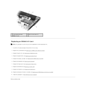
... Page Replace the palm rest (see Replacing the Optical Drive). 5. Replace the WLAN card (seeReplacing a WLAN Card). 9. Insert the I /O Card NOTE: This procedure assumes that you have completed the removal procedure first. 1. Replace the hinge cover (see Replacing the Keyboard). 7. Replace the keyboard (see Replacing the Hinge Cover). 8. 1 system board connector 3 E5500 I/O card 2 M2.5 x 5-mm screws (2) Replacing an E5500 I /O card and replace the...
... Page Replace the palm rest (see Replacing the Optical Drive). 5. Replace the WLAN card (seeReplacing a WLAN Card). 9. Insert the I /O Card NOTE: This procedure assumes that you have completed the removal procedure first. 1. Replace the hinge cover (see Replacing the Keyboard). 7. Replace the keyboard (see Replacing the Hinge Cover). 8. 1 system board connector 3 E5500 I/O card 2 M2.5 x 5-mm screws (2) Replacing an E5500 I /O card and replace the...

Service Manual
Page 37
... fragile, easily dislodged, and time-consuming to replace. Exercise care when removing and handling the keyboard. 1. NOTICE: The key caps on www.dell.com at the top of the keyboard. Back to Contents Page Keyboard Dell™ Latitude™ E5400 and E5500 Service Manual Removing the Keyboard Replacing the Keyboard Removing the Keyboard CAUTION: Before you begin any of the procedures in...
... fragile, easily dislodged, and time-consuming to replace. Exercise care when removing and handling the keyboard. 1. NOTICE: The key caps on www.dell.com at the top of the keyboard. Back to Contents Page Keyboard Dell™ Latitude™ E5400 and E5500 Service Manual Removing the Keyboard Replacing the Keyboard Removing the Keyboard CAUTION: Before you begin any of the procedures in...

Service Manual
Page 38
Replace the hinge cover (see Replacing the Hinge Cover). 5. Press the top right and left side of the keyboard to Contents Page Follow the procedures in place. 4. Back to snap into place. 3. Replace the M2 x 3-mm screws that hold the keyboard in After Working on Your Computer. 2.
Replace the hinge cover (see Replacing the Hinge Cover). 5. Press the top right and left side of the keyboard to Contents Page Follow the procedures in place. 4. Back to snap into place. 3. Replace the M2 x 3-mm screws that hold the keyboard in After Working on Your Computer. 2.


