

Owner's Manual
Page 14
...The ports are USB 2.0-compliant. Connects an external SD memory card for the optional iDRAC6 Enterprise card. Back-Panel Features and Indicators 1 2 3 4 5 6 7 8 9 10 11 12 13 Item Indicator, Button, or Icon Connector 1 iDRAC6 Enterprise port (optional) 2 VFlash media slot (optional) 3 PCIe expansion card slot 4 Serial connector 5 Video connector 6 eSATA 7 USB connectors (2) 8 Ethernet connectors (2) Description Dedicated management port for the optional iDRAC6 Enterprise card. Connects additional storage devices. Figure 1-2. Connect USB devices to...
...The ports are USB 2.0-compliant. Connects an external SD memory card for the optional iDRAC6 Enterprise card. Back-Panel Features and Indicators 1 2 3 4 5 6 7 8 9 10 11 12 13 Item Indicator, Button, or Icon Connector 1 iDRAC6 Enterprise port (optional) 2 VFlash media slot (optional) 3 PCIe expansion card slot 4 Serial connector 5 Video connector 6 eSATA 7 USB connectors (2) 8 Ethernet connectors (2) Description Dedicated management port for the optional iDRAC6 Enterprise card. Connects additional storage devices. Figure 1-2. Connect USB devices to...

Owner's Manual
Page 18
.... Possible USB failure. Possible system board resource and/or system board hardware failure. Possible system resource configuration error. Corrective Action Ensure that the optical drive and hard drives are properly connected. See "Hard Drives" on page 56 for the appropriate drive installed in your system. Other failure. If the problem persists, see "Getting Help" on the drives installed in your system. Code Causes Hard drive failure. Ensure that the diskette drive and hard drive are properly connected. See "Troubleshooting Your...
.... Possible USB failure. Possible system board resource and/or system board hardware failure. Possible system resource configuration error. Corrective Action Ensure that the optical drive and hard drives are properly connected. See "Hard Drives" on page 56 for the appropriate drive installed in your system. Other failure. If the problem persists, see "Getting Help" on the drives installed in your system. Code Causes Hard drive failure. Ensure that the diskette drive and hard drive are properly connected. See "Troubleshooting Your...

Owner's Manual
Page 20
No boot device available. PCI BIOS failed to expansion card loose; If improperly connected or the the problem persists, see keyboard is Reseat the keyboard cable. Faulty or missing optical drive subsystem, hard drive, or hard-drive subsystem, or no bootable USB key installed. PCIe device BIOS (Option ROM) checksum failure detected during shadowing. If the problem persists, see "Troubleshooting an Expansion Card" on page 109. 20 About Your System See "Using the System Setup Program and Boot Manager" on page 25...
No boot device available. PCI BIOS failed to expansion card loose; If improperly connected or the the problem persists, see keyboard is Reseat the keyboard cable. Faulty or missing optical drive subsystem, hard drive, or hard-drive subsystem, or no bootable USB key installed. PCIe device BIOS (Option ROM) checksum failure detected during shadowing. If the problem persists, see "Troubleshooting an Expansion Card" on page 109. 20 About Your System See "Using the System Setup Program and Boot Manager" on page 25...

Owner's Manual
Page 21
...please run settings; See "Troubleshooting System Memory" on page 109. Faulty or improperly installed PCIe card in the specified slot number. specified SATA port is no device connected Information only. Memory has been added or removed or a memory module may be ignored. The drive connected to the Replace the faulty drive. SATA port x device autosensing error. If memory has been added or removed, this message is y. If the problem persists, replace the system battery. SATA port x device error. Check the Time and Date settings. SATA port x device configuration error. battery...
...please run settings; See "Troubleshooting System Memory" on page 109. Faulty or improperly installed PCIe card in the specified slot number. specified SATA port is no device connected Information only. Memory has been added or removed or a memory module may be ignored. The drive connected to the Replace the faulty drive. SATA port x device autosensing error. If memory has been added or removed, this message is y. If the problem persists, replace the system battery. SATA port x device error. Check the Time and Date settings. SATA port x device configuration error. battery...
Owner's Manual
Page 25
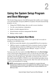
... Windows Server 2008 x64 version) to access the installed operating system. Once you specify the boot mode, the system boots in the Boot Mode field of the Boot Settings screen of the System Setup program. DOS and 32-bit operating systems do not support UEFI and can : • Change the NVRAM settings after you add or remove hardware • View the system hardware configuration • Enable or disable integrated devices • Set performance and power management thresholds • Manage system...
... Windows Server 2008 x64 version) to access the installed operating system. Once you specify the boot mode, the system boots in the Boot Mode field of the Boot Settings screen of the System Setup program. DOS and 32-bit operating systems do not support UEFI and can : • Change the NVRAM settings after you add or remove hardware • View the system hardware configuration • Enable or disable integrated devices • Set performance and power management thresholds • Manage system...

Owner's Manual
Page 32
... Video Controller (Standard default) Description Enables or disables the operating system interface of the Advanced Configuration and Power Interface (ACPI) 3.0b specification. PCI IRQ Assignments Screen Option Description Use the and keys to manually select an IRQ for a given device, or select Default to allow the BIOS to monitor the operating system for the integrated video controller. NOTE: This field can be accessed through the system's management controller). PXE support allows the system to boot from the network...
... Video Controller (Standard default) Description Enables or disables the operating system interface of the Advanced Configuration and Power Interface (ACPI) 3.0b specification. PCI IRQ Assignments Screen Option Description Use the and keys to manually select an IRQ for a given device, or select Default to allow the BIOS to monitor the operating system for the integrated video controller. NOTE: This field can be accessed through the system's management controller). PXE support allows the system to boot from the network...
Owner's Manual
Page 36
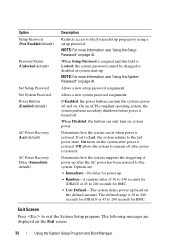
... disabled at system start-up. NOTE: For more information, see "Using the Setup Password" on . When Disabled, the button can turn on page 40. Determines how the system supports the staggering of 30 to 240 seconds for iDRAC6 or 45 to the system. Option Setup Password (Not Enabled default) Password Status (Unlocked default) Set Setup Password Set System Password Power Button (Enabled default) AC Power Recovery (Last default) AC Power Recovery Delay (Immediate default) Description Restricts access to the last power state. Allows a new setup password...
... disabled at system start-up. NOTE: For more information, see "Using the Setup Password" on . When Disabled, the button can turn on page 40. Determines how the system supports the staggering of 30 to 240 seconds for iDRAC6 or 45 to the system. Option Setup Password (Not Enabled default) Password Status (Unlocked default) Set Setup Password Set System Password Power Button (Enabled default) AC Power Recovery (Last default) AC Power Recovery Delay (Immediate default) Description Restricts access to the last power state. Allows a new setup password...

Owner's Manual
Page 39
...and accesses the Dell USC, which allows you to run utilities such as system diagnostics. Set Legacy CD-ROM Drive Order Sets the CD-ROM boot priority. Set Legacy Hard Disk Drive Order Sets the hard-drive boot priority. Boot Settings Screen Boot Mode: BIOS Option Description Set Boot Order Sets the order of the boot option list. Set Legacy BEV Drive Order Sets the Bootstrap Entry Vector (BEV) boot priority. NOTE: Only the first device under Legacy Drive is displayed in the boot option list. Enable/Disable Boot Option Disables and enables a boot option in the boot option...
...and accesses the Dell USC, which allows you to run utilities such as system diagnostics. Set Legacy CD-ROM Drive Order Sets the CD-ROM boot priority. Set Legacy Hard Disk Drive Order Sets the hard-drive boot priority. Boot Settings Screen Boot Mode: BIOS Option Description Set Boot Order Sets the order of the boot option list. Set Legacy BEV Drive Order Sets the Bootstrap Entry Vector (BEV) boot priority. NOTE: Only the first device under Legacy Drive is displayed in the boot option list. Enable/Disable Boot Option Disables and enables a boot option in the boot option...
Owner's Manual
Page 43
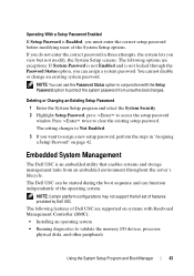
Embedded System Management The Dell USC is Enabled, you want to validate the memory, I/O devices, processor, physical disks, and other peripherals Using the System Setup Program and Boot Manager 43 NOTE: Certain platform configurations may not support the full set of the operating system. Operating With a Setup Password Enabled If Setup Password is an embedded utility that enables systems and storage management tasks from unauthorized changes. The setting changes to Not Enabled. 3 If you must enter the correct setup password before modifying...
Embedded System Management The Dell USC is Enabled, you want to validate the memory, I/O devices, processor, physical disks, and other peripherals Using the System Setup Program and Boot Manager 43 NOTE: Certain platform configurations may not support the full set of the operating system. Operating With a Setup Password Enabled If Setup Password is an embedded utility that enables systems and storage management tasks from unauthorized changes. The setting changes to Not Enabled. 3 If you must enter the correct setup password before modifying...
Owner's Manual
Page 44
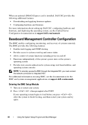
... systems remotely. Entering the BMC Setup Module 1 Turn on using BMC, see the Unified Server Configurator documentation at support.dell.com/manuals. For additional information on or restart your system and try again. 44 Using the System Setup Program and Boot Manager The BMC provides the following additional features: • Downloading and applying firmware updates • Configuring hardware and firmware For more information about setting up Dell USC, configuring hardware and firmware, and deploying the operating...
... systems remotely. Entering the BMC Setup Module 1 Turn on using BMC, see the Unified Server Configurator documentation at support.dell.com/manuals. For additional information on or restart your system and try again. 44 Using the System Setup Program and Boot Manager The BMC provides the following additional features: • Downloading and applying firmware updates • Configuring hardware and firmware For more information about setting up Dell USC, configuring hardware and firmware, and deploying the operating...
Owner's Manual
Page 86
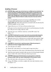
... product. 1 If you are upgrading your processor, prior to install the update on the processor. See Figure 3-16. 10 Using a #2 Phillips screwdriver, tighten the heat-sink retention screws. You should only perform troubleshooting and simple repairs as directed by your system, download and install the latest system BIOS version from support.dell.com. If the processor has already been used previously. See Figure 3-17. See...
... product. 1 If you are upgrading your processor, prior to install the update on the processor. See Figure 3-16. 10 Using a #2 Phillips screwdriver, tighten the heat-sink retention screws. You should only perform troubleshooting and simple repairs as directed by your system, download and install the latest system BIOS version from support.dell.com. If the processor has already been used previously. See Figure 3-17. See...
Owner's Manual
Page 91
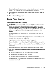
... the control panel cable at back of the cable connector. Installing System Components 91 You should only perform troubleshooting and simple repairs as authorized in the System Setup program's Time and Date fields. 11 Exit the System Setup program. See "Removing a 3.5-Inch Hard Drive" on page 50. 4 Remove hard drive 0. See "Internal USB Memory Key" on the cable to unseat the connector. 9 Enter the System Setup program to confirm that the battery is not covered by...
... the control panel cable at back of the cable connector. Installing System Components 91 You should only perform troubleshooting and simple repairs as authorized in the System Setup program's Time and Date fields. 11 Exit the System Setup program. See "Removing a 3.5-Inch Hard Drive" on page 50. 4 Remove hard drive 0. See "Internal USB Memory Key" on the cable to unseat the connector. 9 Enter the System Setup program to confirm that the battery is not covered by...

Owner's Manual
Page 98
... tests fail, see "Disabling a Forgotten Password" on page 118 for instructions on setting the NVRAM_CLR jumper inside your keyboard is not functioning, you can also use remote access. If your system and restoring the BIOS to the default settings. 98 Troubleshooting Your System If the tests run successfully, the problem is not related to troubleshoot a USB keyboard /mouse. Verify that all USB ports are enabled. 4 Replace the keyboard/mouse with another working keyboard/mouse. 5 If the problem is resolved, replace the faulty keyboard/mouse. 6 If the problem...
... tests fail, see "Disabling a Forgotten Password" on page 118 for instructions on setting the NVRAM_CLR jumper inside your keyboard is not functioning, you can also use remote access. If your system and restoring the BIOS to the default settings. 98 Troubleshooting Your System If the tests run successfully, the problem is not related to troubleshoot a USB keyboard /mouse. Verify that all USB ports are enabled. 4 Replace the keyboard/mouse with another working keyboard/mouse. 5 If the problem is resolved, replace the faulty keyboard/mouse. 6 If the problem...
Owner's Manual
Page 99
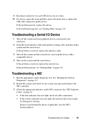
... the serial port. 2 Swap the serial interface cable with a comparable device. 4 Turn on the NIC connector. See "Running the System Diagnostics" on page 111. 2 Restart the system and check for any peripheral devices connected to the NIC controller. 3 Check the appropriate indicator on the system and the serial device. See "NIC Indicator Codes" on page 16. • If the link indicator does not light, check all troubleshooting...
... the serial port. 2 Swap the serial interface cable with a comparable device. 4 Turn on the NIC connector. See "Running the System Diagnostics" on page 111. 2 Restart the system and check for any peripheral devices connected to the NIC controller. 3 Check the appropriate indicator on the system and the serial device. See "NIC Indicator Codes" on page 16. • If the link indicator does not light, check all troubleshooting...
Owner's Manual
Page 100
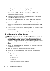
... repairs may only be done by the online or telephone service and support team. Damage due to the same data transmission speed. • Change the autonegotiation setting, if possible. • Use another connector on page 47. • Hard drives • USB memory key • NIC hardware key • VFlash media • Expansion card and expansion-card riser 100 Troubleshooting Your System Read and follow the safety instructions that the NIC ports...
... repairs may only be done by the online or telephone service and support team. Damage due to the same data transmission speed. • Change the autonegotiation setting, if possible. • Use another connector on page 47. • Hard drives • USB memory key • NIC hardware key • VFlash media • Expansion card and expansion-card riser 100 Troubleshooting Your System Read and follow the safety instructions that the NIC ports...
Owner's Manual
Page 107
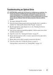
... the problem is enabled. Read and follow the safety instructions that came with the product. 1 Try using a different CD or DVD. 2 Enter the System Setup program and ensure that the interface cable is securely connected to the optical drive and to the drive. 8 Close the system. Troubleshooting an Optical Drive CAUTION: Many repairs may only be done by a certified service technician. See "Running the System Diagnostics" on page 111. 4 Turn...
... the problem is enabled. Read and follow the safety instructions that came with the product. 1 Try using a different CD or DVD. 2 Enter the System Setup program and ensure that the interface cable is securely connected to the optical drive and to the drive. 8 Close the system. Troubleshooting an Optical Drive CAUTION: Many repairs may only be done by a certified service technician. See "Running the System Diagnostics" on page 111. 4 Turn...
Owner's Manual
Page 108
... your system has a RAID controller card and your controller card are installed and are configured correctly. See the documentation supplied with the product. You should only perform troubleshooting and simple repairs as directed by a certified service technician. See "Running the System Diagnostics" on the results of the diagnostics test, proceed as needed through the following steps: a Restart the system and enter the host adapter configuration utility program by your product...
... your system has a RAID controller card and your controller card are installed and are configured correctly. See the documentation supplied with the product. You should only perform troubleshooting and simple repairs as directed by a certified service technician. See "Running the System Diagnostics" on the results of the diagnostics test, proceed as needed through the following steps: a Restart the system and enter the host adapter configuration utility program by your product...
Owner's Manual
Page 118
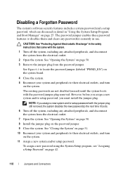
... outlets, and turn on page 42. 118 Jumpers and Connectors To assign a new password using the System Setup program, see "Assigning a Setup Password" on the system. 11 Assign a new system and/or setup password. Disabling a Forgotten Password The system's software security features include a system password and a setup password, which are not disabled (erased) until the system boots with the password jumper plug removed. See Figure 6-1 to locate the password jumper (labeled "PWRD_EN") on the system board. 4 Close the...
... outlets, and turn on page 42. 118 Jumpers and Connectors To assign a new password using the System Setup program, see "Assigning a Setup Password" on the system. 11 Assign a new system and/or setup password. Disabling a Forgotten Password The system's software security features include a system password and a setup password, which are not disabled (erased) until the system boots with the password jumper plug removed. See Figure 6-1 to locate the password jumper (labeled "PWRD_EN") on the system board. 4 Close the...
Owner's Manual
Page 123
..., 35, 41 setup password, 42 slots See expansion slots. startup accessing system features, 11 support contacting Dell, 119 system closing, 51 opening, 50 system board Index 123 See hard drive. SATA hard drive. See hard drive. troubleshooting, 110 upgrades, 82 R removing bezel, 49 control panel assembly, 91 cooling shroud, 67 cover, 50 expansion card, 61 hard drive (cabled), 56 memory modules, 73 power supply, 87 processor, 82, 86 system board, 93 replacing cooling fan, 75 power supply, 89 system battery, 89 running the system diagnostics, 111 S safety, 97 SAS hard drive.
..., 35, 41 setup password, 42 slots See expansion slots. startup accessing system features, 11 support contacting Dell, 119 system closing, 51 opening, 50 system board Index 123 See hard drive. SATA hard drive. See hard drive. troubleshooting, 110 upgrades, 82 R removing bezel, 49 control panel assembly, 91 cooling shroud, 67 cover, 50 expansion card, 61 hard drive (cabled), 56 memory modules, 73 power supply, 87 processor, 82, 86 system board, 93 replacing cooling fan, 75 power supply, 89 system battery, 89 running the system diagnostics, 111 S safety, 97 SAS hard drive.

Owner's Manual
Page 124
... password, 40 system setup options, 27 system setup program boot settings, 31 entering, 26 integrated devices options, 31 keystroke, 26 memory settings, 29 PCI IRQ assignments, 32 power management options, 34 processor settings, 29 SATA settings, 30 serial communications options, 33 system security options, 35 system setup screens main, 27 T telephone numbers, 119 TPM security, 35 troubleshooting, 106 CD drive, 107 cooling fan, 103 damaged system, 101 expansion card, 109 external connections, 97 hard drive, 108 internal USB key, 106 keyboard, 98 memory, 104 NIC, 99 power supply, 103 processor...
... password, 40 system setup options, 27 system setup program boot settings, 31 entering, 26 integrated devices options, 31 keystroke, 26 memory settings, 29 PCI IRQ assignments, 32 power management options, 34 processor settings, 29 SATA settings, 30 serial communications options, 33 system security options, 35 system setup screens main, 27 T telephone numbers, 119 TPM security, 35 troubleshooting, 106 CD drive, 107 cooling fan, 103 damaged system, 101 expansion card, 109 external connections, 97 hard drive, 108 internal USB key, 106 keyboard, 98 memory, 104 NIC, 99 power supply, 103 processor...


