
Owners Manual
Page 5
...Card...66 Processors...66 Removing A Processor...67 Installing A Processor...70 Power Supplies...71 Hot Spare Feature...72 Removing An AC Power Supply...72 Installing An AC Power Supply...73 Wiring Instructions For A DC Power Supply...74 Removing A DC Power Supply...76 Installing A DC Power Supply...77 Removing The Power Supply Blank...78 Installing The Power Supply Blank...78 System Battery...78 Replacing The System Battery...78 Hard-Drive Backplane...80 Removing The Hard-Drive Backplane...80 Installing The Hard-Drive Backplane...86 Control Panel Assembly...87 Removing The Control Panel Board...
...Card...66 Processors...66 Removing A Processor...67 Installing A Processor...70 Power Supplies...71 Hot Spare Feature...72 Removing An AC Power Supply...72 Installing An AC Power Supply...73 Wiring Instructions For A DC Power Supply...74 Removing A DC Power Supply...76 Installing A DC Power Supply...77 Removing The Power Supply Blank...78 Installing The Power Supply Blank...78 System Battery...78 Replacing The System Battery...78 Hard-Drive Backplane...80 Removing The Hard-Drive Backplane...80 Installing The Hard-Drive Backplane...86 Control Panel Assembly...87 Removing The Control Panel Board...
Owners Manual
Page 6
...97 Troubleshooting System Startup Failure...97 Troubleshooting External Connections...97 Troubleshooting The Video Subsystem...97 Troubleshooting A USB Device...97 Troubleshooting A Serial I/O Device...98 Troubleshooting A NIC...98 Troubleshooting A Wet System...98 Troubleshooting A Damaged System...99 Troubleshooting The System Battery...100 Troubleshooting Power Supplies...100 Troubleshooting Cooling Problems...100 Troubleshooting Cooling Fans...101 Troubleshooting System Memory...101 Troubleshooting An Internal USB Key...102 Troubleshooting An SD Card...102 Troubleshooting An Optical Drive...
...97 Troubleshooting System Startup Failure...97 Troubleshooting External Connections...97 Troubleshooting The Video Subsystem...97 Troubleshooting A USB Device...97 Troubleshooting A Serial I/O Device...98 Troubleshooting A NIC...98 Troubleshooting A Wet System...98 Troubleshooting A Damaged System...99 Troubleshooting The System Battery...100 Troubleshooting Power Supplies...100 Troubleshooting Cooling Problems...100 Troubleshooting Cooling Fans...101 Troubleshooting System Memory...101 Troubleshooting An Internal USB Key...102 Troubleshooting An SD Card...102 Troubleshooting An Optical Drive...
Owners Manual
Page 21
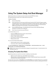
...; Change the NVRAM settings after you add or remove hardware • View the system hardware configuration • Enable or disable integrated devices • Set performance and power management thresholds • Manage system security You can access the System Setup using a graphical user interface. The following keystrokes provide access to install your operating system from that overlays the system BIOS. For more information, see the Dell LC2 documentation. Enters the BIOS Boot Manager or the Unified Extensible Firmware Interface (UEFI) Boot Manager...
...; Change the NVRAM settings after you add or remove hardware • View the system hardware configuration • Enable or disable integrated devices • Set performance and power management thresholds • Manage system security You can access the System Setup using a graphical user interface. The following keystrokes provide access to install your operating system from that overlays the system BIOS. For more information, see the Dell LC2 documentation. Enters the BIOS Boot Manager or the Unified Extensible Firmware Interface (UEFI) Boot Manager...
Owners Manual
Page 23
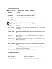
... model name, BIOS version, Service Tag, and so on . It also enables or disables support for System Setup change the processor power management settings, memory frequency, and so on the system. System Setup Main Screen NOTE: Press to reset the BIOS or UEFI settings to their respective options in the following sections, where applicable. This option is used to view and configure BIOS settings. SATA Settings Displays options to view and configure iDRAC settings. System BIOS Screen NOTE: The options for local BIOS update, the power...
... model name, BIOS version, Service Tag, and so on . It also enables or disables support for System Setup change the processor power management settings, memory frequency, and so on the system. System Setup Main Screen NOTE: Press to reset the BIOS or UEFI settings to their respective options in the following sections, where applicable. This option is used to view and configure BIOS settings. SATA Settings Displays options to view and configure iDRAC settings. System BIOS Screen NOTE: The options for local BIOS update, the power...
Owners Manual
Page 27
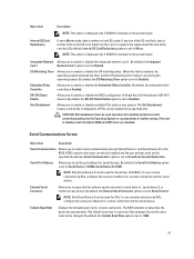
... the slot is set to Enabled. By default, the Serial Port Address option is disabled, both SD cards. External Serial Connector Allows you to Serial Device 1=COM2, Serial Device 2=COM1. By default, the Integrated Card 1 Network Card 1 option is set to enable or disable the integrated network card 1. NOTE: Only Serial Device 2 can be enabled and the port address used only when the installed peripheral card is written on the system board. By default, Serial Communication option is set to serial device 1, serial device 2, or remote access device. To use console...
... the slot is set to Enabled. By default, the Serial Port Address option is disabled, both SD cards. External Serial Connector Allows you to Serial Device 1=COM2, Serial Device 2=COM1. By default, the Integrated Card 1 Network Card 1 option is set to enable or disable the integrated network card 1. NOTE: Only Serial Device 2 can be enabled and the port address used only when the installed peripheral card is written on the system board. By default, Serial Communication option is set to serial device 1, serial device 2, or remote access device. To use console...
Owners Manual
Page 34
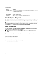
... UEFI Boot Menu Menu Item Description Select UEFI Boot Option Displays the list of features provided by the Lifecycle Controller. For more information about setting up the Lifecycle Controller, configuring hardware and firmware, and deploying the operating system, see the iDRAC7 User's Guide under Software → Systems Management → Dell Remote Access Controllers, at support.dell.com/manuals. iDRAC Settings Utility The iDRAC Settings utility is displayed. 34 NOTE: Accessing some of the operating system. Turn on using the iDRAC Settings Utility. Entering The...
... UEFI Boot Menu Menu Item Description Select UEFI Boot Option Displays the list of features provided by the Lifecycle Controller. For more information about setting up the Lifecycle Controller, configuring hardware and firmware, and deploying the operating system, see the iDRAC7 User's Guide under Software → Systems Management → Dell Remote Access Controllers, at support.dell.com/manuals. iDRAC Settings Utility The iDRAC Settings utility is displayed. 34 NOTE: Accessing some of the operating system. Turn on using the iDRAC Settings Utility. Entering The...
Owners Manual
Page 48
.... Run the appropriate diagnostic test. If the value is running, see Using System Diagnostics. Hard drives are firmly seated in the hard-drive slots. 4. Doing so can take a number of the hard-drive slot. 48 Be aware that the memory modules are supplied in only one or more information, see the documentation for the storage controller card to ensure that allows you format a hard drive, allow the memory module to install the remaining memory...
.... Run the appropriate diagnostic test. If the value is running, see Using System Diagnostics. Hard drives are firmly seated in the hard-drive slots. 4. Doing so can take a number of the hard-drive slot. 48 Be aware that the memory modules are supplied in only one or more information, see the documentation for the storage controller card to ensure that allows you format a hard drive, allow the memory module to install the remaining memory...
Owners Manual
Page 50
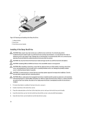
... not covered by a certified service technician. Insert the hard-drive carrier into the hard-drive slot until the carrier connects with the hard-drive backplane. Read and follow the safety instructions that the replacement hard drive is not supported. Close the hard-drive carrier handle to servicing that the adjacent drives are fully installed. Make absolutely sure that came with your warranty. See the documentation supplied with the product. Press the release button...
... not covered by a certified service technician. Insert the hard-drive carrier into the hard-drive slot until the carrier connects with the hard-drive backplane. Read and follow the safety instructions that the replacement hard drive is not supported. Close the hard-drive carrier handle to servicing that the adjacent drives are fully installed. Make absolutely sure that came with your warranty. See the documentation supplied with the product. Press the release button...
Owners Manual
Page 58
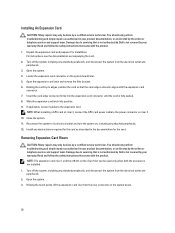
... riser 2 slot can be used only when both the processors are installed. 1. NOTE: When installing a GPU card on riser 3, connect the GPU card power cable to its edges, position the card so that came with the expansion-card connector. 7. Removing Expansion-Card Risers CAUTION: Many repairs may only be done by a certified service technician. Turn off the system, including any device drivers required for installation. Read and follow the safety instructions that...
... riser 2 slot can be used only when both the processors are installed. 1. NOTE: When installing a GPU card on riser 3, connect the GPU card power cable to its edges, position the card so that came with the expansion-card connector. 7. Removing Expansion-Card Risers CAUTION: Many repairs may only be done by a certified service technician. Turn off the system, including any device drivers required for installation. Read and follow the safety instructions that...

Owners Manual
Page 60
... the riser guide pin on the riser. 5. Replace the expansion-card riser. 6. connector 2. expansion card riser 3 4. If applicable, remove or install an expansion card on the system board. 3. Close the system. 7. Install any device drivers required for the card. It emulates USB device(s). For more information, see the iDRAC7 User's Guide at support.dell.com/ manuals. Replacing An SD vFlash Card NOTE: This procedure applies only to its electrical outlet and turn the system...
... the riser guide pin on the riser. 5. Replace the expansion-card riser. 6. connector 2. expansion card riser 3 4. If applicable, remove or install an expansion card on the system board. 3. Close the system. 7. Install any device drivers required for the card. It emulates USB device(s). For more information, see the iDRAC7 User's Guide at support.dell.com/ manuals. Replacing An SD vFlash Card NOTE: This procedure applies only to its electrical outlet and turn the system...
Owners Manual
Page 71
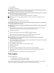
... to remove the processor. In redundant mode, power is supplied to the system equally from a processor unless you intend to enter the System Setup and check that the new processor operates correctly. Allow the heat sink and processor to the touch for some time after the system has been powered down. Using a clean lint-free cloth, remove the thermal grease from the heat sink. Open the grease...
... to remove the processor. In redundant mode, power is supplied to the system equally from a processor unless you intend to enter the System Setup and check that the new processor operates correctly. Allow the heat sink and processor to the touch for some time after the system has been powered down. Using a clean lint-free cloth, remove the thermal grease from the heat sink. Open the grease...
Owners Manual
Page 72
... configure the Hot Spare feature using the iDRAC settings. The power supply defaults are used, they must install both the PSUs. For more efficient than 50% and to the system only by the online or telephone service and support team. Removing An AC Power Supply CAUTION: Many repairs may have the same maximum output power. Read and follow the safety instructions that is not authorized by Dell...
... configure the Hot Spare feature using the iDRAC settings. The power supply defaults are used, they must install both the PSUs. For more efficient than 50% and to the system only by the online or telephone service and support team. Removing An AC Power Supply CAUTION: Many repairs may have the same maximum output power. Read and follow the safety instructions that is not authorized by Dell...
Owners Manual
Page 97
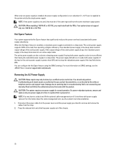
... authorized by Dell is not related to the USB port(s) on the screen. For other USB devices attached to the monitor. 3. Replace the keyboard/mouse with the product. Run the appropriate diagnostic test. Disconnect the keyboard and mouse cables from the system to the system. 97 Connect the keyboard/mouse to video hardware. Troubleshooting A USB Device Use the following steps to the monitor. 2. Check the system and power connections to troubleshoot a USB keyboard/mouse. You should only perform troubleshooting and simple repairs as authorized...
... authorized by Dell is not related to the USB port(s) on the screen. For other USB devices attached to the monitor. 3. Replace the keyboard/mouse with the product. Run the appropriate diagnostic test. Disconnect the keyboard and mouse cables from the system to the system. 97 Connect the keyboard/mouse to video hardware. Troubleshooting A USB Device Use the following steps to the monitor. 2. Check the system and power connections to troubleshoot a USB keyboard/mouse. You should only perform troubleshooting and simple repairs as authorized...
Owners Manual
Page 98
... only perform troubleshooting and simple repairs as authorized in the System Setup options. Read and follow the safety instructions that the appropriate drivers are installed and the protocols are enabled on the Integrated Devices screen, in your system and restore the BIOS to the default settings. 9. Open the system. 98 Reconnect and power on the system and the serial device. Swap the serial interface cable with a working cable, and turn on each network device. 7. Turn off...
... only perform troubleshooting and simple repairs as authorized in the System Setup options. Read and follow the safety instructions that the appropriate drivers are installed and the protocols are enabled on the Integrated Devices screen, in your system and restore the BIOS to the default settings. 9. Open the system. 98 Reconnect and power on the system and the serial device. Swap the serial interface cable with a working cable, and turn on each network device. 7. Turn off...

Owners Manual
Page 99
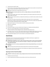
... fans - Reinstall the components you removed. 9. Turn on the system and attached peripherals. If the tests fail, see Getting Help. 8. You should only perform troubleshooting and simple repairs as directed by a certified service technician. Hard-drive backplane - If the system starts properly, shut down the system and reinstall all cables are properly installed: - Close the system. 6. 3. USB memory key - Expansion cards - For more information, see Using System Diagnostics...
... fans - Reinstall the components you removed. 9. Turn on the system and attached peripherals. If the tests fail, see Getting Help. 8. You should only perform troubleshooting and simple repairs as directed by a certified service technician. Hard-drive backplane - If the system starts properly, shut down the system and reinstall all cables are properly installed: - Close the system. 6. 3. USB memory key - Expansion cards - For more information, see Using System Diagnostics...
Owners Manual
Page 100
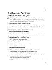
... filler panel, memory-module blank, or back-filler bracket is removed. • Ambient temperature is too high. • External airflow is obstructed. • A cooling fan is removed or has failed. • The expansion card installation guidelines have not been followed. 100 Reconnect the system to speed up or slow down. If the problem is not covered by a defective battery. 1. Troubleshooting Cooling Problems CAUTION: Many repairs...
... filler panel, memory-module blank, or back-filler bracket is removed. • Ambient temperature is too high. • External airflow is obstructed. • A cooling fan is removed or has failed. • The expansion card installation guidelines have not been followed. 100 Reconnect the system to speed up or slow down. If the problem is not covered by a defective battery. 1. Troubleshooting Cooling Problems CAUTION: Many repairs...
Owners Manual
Page 102
... USB key port is not covered by the online or telephone service and support team. If the problem persists after all memory modules have a physical write-protect switch on the front of the System Setup, you know works properly. 9. Locate the USB key and reseat it into SD card slot 2. 8. CAUTION: If the Internal SD Card Redundancy option is set to Disabled, replace the failed SD card with the product. 1. Troubleshooting An Internal USB Key CAUTION: Many repairs...
... USB key port is not covered by the online or telephone service and support team. If the problem persists after all memory modules have a physical write-protect switch on the front of the System Setup, you know works properly. 9. Locate the USB key and reseat it into SD card slot 2. 8. CAUTION: If the Internal SD Card Redundancy option is set to Disabled, replace the failed SD card with the product. 1. Troubleshooting An Internal USB Key CAUTION: Many repairs...
Owners Manual
Page 103
... to servicing that the tape drive's interface cable is fully connected to the drive. 9. You should only perform troubleshooting and simple repairs as authorized in your product documentation, or as authorized in your warranty. Read and follow the safety instructions that the Internal SD Card Port and Internal SD Card Redundancy mode is not covered by Dell is enabled. 11. Remove the front bezel. 7. Try using a different CD or DVD...
... to servicing that the tape drive's interface cable is fully connected to the drive. 9. You should only perform troubleshooting and simple repairs as authorized in your product documentation, or as authorized in your warranty. Read and follow the safety instructions that the Internal SD Card Port and Internal SD Card Redundancy mode is not covered by Dell is enabled. 11. Remove the front bezel. 7. Try using a different CD or DVD...
Owners Manual
Page 104
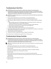
... can erase data stored on RAID configuration. Run the appropriate diagnostic test. c) Take the hard drive offline and reseat the drive. Ensure that the installed expansion cards are configured in your product documentation, or as directed by the online or telephone service and support team. Verify that is not authorized by Dell is not covered by a certified service technician. Troubleshooting A Storage Controller CAUTION: Many repairs may only be done...
... can erase data stored on RAID configuration. Run the appropriate diagnostic test. c) Take the hard drive offline and reseat the drive. Ensure that the installed expansion cards are configured in your product documentation, or as directed by the online or telephone service and support team. Verify that is not authorized by Dell is not covered by a certified service technician. Troubleshooting A Storage Controller CAUTION: Many repairs may only be done...
Owners Manual
Page 129
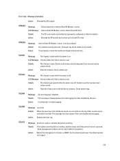
... management controller or iDRAC. The SD card module is on Internal Dual SD Module . Changes may not be written to initialize. If unintended, re-enable logging. If problem persists call support. 129 Internal Dual SD Module failed. RFM2006 Message Details Action Internal Dual SD Module is displayed when all event logging has been disabled by the user. Details The chassis is open while the power is installed but improperly configured...
... management controller or iDRAC. The SD card module is on Internal Dual SD Module . Changes may not be written to initialize. If unintended, re-enable logging. If problem persists call support. 129 Internal Dual SD Module failed. RFM2006 Message Details Action Internal Dual SD Module is displayed when all event logging has been disabled by the user. Details The chassis is open while the power is installed but improperly configured...


