

Comprehensive Specifications
Page 1
...Mobility Radeon, and AMD Athlon are trademarks or registered trademarks of Intel Corporation in any proprietary interest in this text: Dell and Inspiron are trademarks of your computer, click Start ® Help and Support and select the option to Top Drives and Devices Computer Model...width External bus frequency - 133 MHz Inspiron 400 AMD Athlon™ AMD Athlon X2 512 KB 1 MB 64 bits 200 MHz Back to view information about your computer. Processor Drives and Devices Memory Computer Information Expansion Bus Video Audio Memory Card Reader System Board Connectors External ...
...Mobility Radeon, and AMD Athlon are trademarks or registered trademarks of Intel Corporation in any proprietary interest in this text: Dell and Inspiron are trademarks of your computer, click Start ® Help and Support and select the option to Top Drives and Devices Computer Model...width External bus frequency - 133 MHz Inspiron 400 AMD Athlon™ AMD Athlon X2 512 KB 1 MB 64 bits 200 MHz Back to view information about your computer. Processor Drives and Devices Memory Computer Information Expansion Bus Video Audio Memory Card Reader System Board Connectors External ...

Comprehensive Specifications
Page 2
...insp300/en/cs/index.htm[7/25/2012 8:50:34 AM] non-ECC memory only 1 GB, 2 GB, and 4 GB 1 GB, 2 GB, 3 GB, 4 GB, 6 GB, and 8 GB Back to Top Computer Information Computer Model Inspiron 300 System chipset Intel 945GC Data bus width DRAM bus width Processor ...AMD® 780G 64 bits - - 8 MB 800 MHz Back to Top Memory Computer Model Inspiron 300 Connectors one Minimum 1 GB Maximum 1 GB Memory type 533 MHz DDR2 UDIMM; non-ECC memory only Memory capacities 1 GB Memory configurations possible 1 GB Inspiron 400 two 1 GB 8 GB 800 MHz DDR2 SODIMM; index.htm: (optional...
...insp300/en/cs/index.htm[7/25/2012 8:50:34 AM] non-ECC memory only 1 GB, 2 GB, and 4 GB 1 GB, 2 GB, 3 GB, 4 GB, 6 GB, and 8 GB Back to Top Computer Information Computer Model Inspiron 300 System chipset Intel 945GC Data bus width DRAM bus width Processor ...AMD® 780G 64 bits - - 8 MB 800 MHz Back to Top Memory Computer Model Inspiron 300 Connectors one Minimum 1 GB Maximum 1 GB Memory type 533 MHz DDR2 UDIMM; non-ECC memory only Memory capacities 1 GB Memory configurations possible 1 GB Inspiron 400 two 1 GB 8 GB 800 MHz DDR2 SODIMM; index.htm: (optional...
Comprehensive Specifications
Page 4
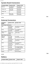
... Back to Top External Connectors Computer Model Inspiron 300 Inspiron 400 Front Panel Connectors USB two USB 2.0compliant connectors two USB 2.0-compliant connectors Audio one headphone one headphone connector connector Memory card reader one 4-in-1 memory card reader one 4-in-1 memory card reader Back Panel Connectors Network adapter ... one HDMI connector Power one AC adapter one 4-pin connector - index.htm: System Board Connectors Computer Model Memory Chassis fan Graphic fan Inspiron 300 one 240-pin connector one AC adapter connector connector eSATA -
... Back to Top External Connectors Computer Model Inspiron 300 Inspiron 400 Front Panel Connectors USB two USB 2.0compliant connectors two USB 2.0-compliant connectors Audio one headphone one headphone connector connector Memory card reader one 4-in-1 memory card reader one 4-in-1 memory card reader Back Panel Connectors Network adapter ... one HDMI connector Power one AC adapter one 4-pin connector - index.htm: System Board Connectors Computer Model Memory Chassis fan Graphic fan Inspiron 300 one 240-pin connector one AC adapter connector connector eSATA -

Service Manual
Page 1
...Dell™ Inspiron™ 300/400 Service Manual Technical Overview Before You Begin Top Cover Bottom Cover Top Bracket I/O Bezel Optical Drive Drive Bay Power-Button Bracket Coin-Cell Battery Hard Drive Wireless Mini-Card (Inspiron 400 Only) Memory Module(s) Processor Heat Sink (Inspiron 400 Only) Processor (Inspiron... the United States and/or other than its own. Other trademarks and trade names may be used in this text: Dell, the DELL logo, and Inspiron are either the entities claiming the marks and names or their products. WARNING: A WARNING indicates a potential for property ...
...Dell™ Inspiron™ 300/400 Service Manual Technical Overview Before You Begin Top Cover Bottom Cover Top Bracket I/O Bezel Optical Drive Drive Bay Power-Button Bracket Coin-Cell Battery Hard Drive Wireless Mini-Card (Inspiron 400 Only) Memory Module(s) Processor Heat Sink (Inspiron 400 Only) Processor (Inspiron... the United States and/or other than its own. Other trademarks and trade names may be used in this text: Dell, the DELL logo, and Inspiron are either the entities claiming the marks and names or their products. WARNING: A WARNING indicates a potential for property ...
Service Manual
Page 26
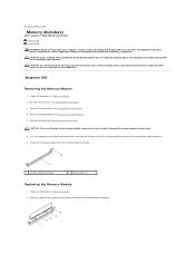
...your computer. Align the notch on the memory module with your computer. Remove the top cover (see Removing the Drive Bay). Back to Contents Page Memory Module(s) Dell™ Inspiron™ 300/400 Service Manual Inspiron 300 Inspiron 400 WARNING: Before working inside your computer,... read the safety information that is not authorized by Dell™ is not covered by periodically touching an ...
...your computer. Align the notch on the memory module with your computer. Remove the top cover (see Removing the Drive Bay). Back to Contents Page Memory Module(s) Dell™ Inspiron™ 300/400 Service Manual Inspiron 300 Inspiron 400 WARNING: Before working inside your computer,... read the safety information that is not authorized by Dell™ is not covered by periodically touching an ...
Service Manual
Page 27
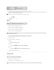
.... 8. Connect your computer. 10. If you insert the memory module correctly, the securing clips snap into position, remove the memory module and reinstall it. Replace the optical drive (see Removing the Bottom Cover). Inspiron 400 Removing the Memory Module(s) 1. Follow the procedures in damage to the memory module connector, do so may not boot. 1 cutouts...
.... 8. Connect your computer. 10. If you insert the memory module correctly, the securing clips snap into position, remove the memory module and reinstall it. Replace the optical drive (see Removing the Bottom Cover). Inspiron 400 Removing the Memory Module(s) 1. Follow the procedures in damage to the memory module connector, do so may not boot. 1 cutouts...
Service Manual
Page 28
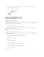
...Cover). If the message appears stating that the memory is not installed properly, the computer may result in damage to install memory modules in two connectors, install a memory module in the connector labeled "DIMM 1" before you install a memory module in the connector labeled "DIMM 2." ... each end of memory (RAM) listed. Failure to do not hear the click, remove the memory module and reinstall it clicks into place. Remove the memory module from the memory-module connector. 1 tab 3 memory module 2 memory-module connector 4 securing clips (2) Replacing the Memory Module(s) CAUTION: ...
...Cover). If the message appears stating that the memory is not installed properly, the computer may result in damage to install memory modules in two connectors, install a memory module in the connector labeled "DIMM 1" before you install a memory module in the connector labeled "DIMM 2." ... each end of memory (RAM) listed. Failure to do not hear the click, remove the memory module and reinstall it clicks into place. Remove the memory module from the memory-module connector. 1 tab 3 memory module 2 memory-module connector 4 securing clips (2) Replacing the Memory Module(s) CAUTION: ...

Service Manual
Page 38
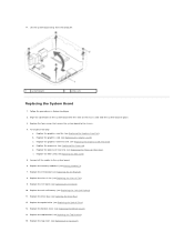
... Board 1. Remove the bottom cover (see Removing the Graphics Card). Remove the drive bay (see Memory Module(s)). 12. Remove the I/O bracket (see Removing the I /O Bezel). 9. b. Remove the memory module(s) (see Removing the Drive Bay). 7. f. Remove the four screws that is not authorized ... safety information that provides a utility for transferring the Service Tag to the chassis. 15. Back to Contents Page System Board Dell™ Inspiron™ 300/400 Service Manual Removing the System Board Replacing the System Board Entering the Service Tag in Before You Begin. ...
... Board 1. Remove the bottom cover (see Removing the Graphics Card). Remove the drive bay (see Memory Module(s)). 12. Remove the I/O bracket (see Removing the I /O Bezel). 9. b. Remove the memory module(s) (see Removing the Drive Bay). 7. f. Remove the four screws that is not authorized ... safety information that provides a utility for transferring the Service Tag to the chassis. 15. Back to Contents Page System Board Dell™ Inspiron™ 300/400 Service Manual Removing the System Board Replacing the System Board Entering the Service Tag in Before You Begin. ...
Service Manual
Page 39
...Cell Battery). 11. Replace the coin-cell battery (see Replacing the Optical Drive). 13. b. c. Replace the memory module(s) (see Replacing the Processor Heat Sink). 17. Replace the processor heat sink (see Memory Module(s)). 7. Replace the chassis fan (see Replacing the I /O bezel (see Replacing the Chassis Fan). 9. Replace...the top bracket (see Replacing the Graphics Card). Replace the top cover (see Replacing the Graphics-Card Fan). For Inspiron 400 Only: a. Replace the graphics-card fan (see Replacing the Top Cover). Connect all the cables to the chassis. 4.
...Cell Battery). 11. Replace the coin-cell battery (see Replacing the Optical Drive). 13. b. c. Replace the memory module(s) (see Replacing the Processor Heat Sink). 17. Replace the processor heat sink (see Memory Module(s)). 7. Replace the chassis fan (see Replacing the I /O bezel (see Replacing the Chassis Fan). 9. Replace...the top bracket (see Replacing the Graphics Card). Replace the top cover (see Replacing the Graphics-Card Fan). For Inspiron 400 Only: a. Replace the graphics-card fan (see Replacing the Top Cover). Connect all the cables to the chassis. 4.

Service Manual
Page 41
...field. NOTE: Before you change system setup, it , and then press . This prompt can make that define the configuration of memory installed in MB In this program. Press to make your computer work incorrectly. System Info System BIOS Version Service Tag Asset Tag ...current or changeable configuration information for the F2 prompt to appear and then press immediately. Back to Contents Page System Setup Utility Dell™ Inspiron™ 300/400 Service Manual Overview Clearing Forgotten Passwords and CMOS Settings Flashing the BIOS Overview Use system setup utility to:...
...field. NOTE: Before you change system setup, it , and then press . This prompt can make that define the configuration of memory installed in MB In this program. Press to make your computer work incorrectly. System Info System BIOS Version Service Tag Asset Tag ...current or changeable configuration information for the F2 prompt to appear and then press immediately. Back to Contents Page System Setup Utility Dell™ Inspiron™ 300/400 Service Manual Overview Clearing Forgotten Passwords and CMOS Settings Flashing the BIOS Overview Use system setup utility to:...
Service Manual
Page 42
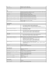
... in MHz Indicates the type of installed memory Main Service Tag Setting System Time System Date SATA-0 SATA-1 eSATA-0 (applicable for Inspiron 400 computer only) eSATA-1 (applicable for Inspiron 400 computer only) Keyboard Errors Displays the service tag of the computer if the service tag is present or provides a ... or Off (On by default) Enabled or Disabled (Enabled by default) Power Management ACPI Suspend Type AC Recovery Low Power Mode (applicable for Inspiron 400 computer only) Remote Wake Up Auto Power On Auto Power On Date (Displays only when "Auto Power On" is set to Enabled) Auto...
... in MHz Indicates the type of installed memory Main Service Tag Setting System Time System Date SATA-0 SATA-1 eSATA-0 (applicable for Inspiron 400 computer only) eSATA-1 (applicable for Inspiron 400 computer only) Keyboard Errors Displays the service tag of the computer if the service tag is present or provides a ... or Off (On by default) Enabled or Disabled (Enabled by default) Power Management ACPI Suspend Type AC Recovery Low Power Mode (applicable for Inspiron 400 computer only) Remote Wake Up Auto Power On Auto Power On Date (Displays only when "Auto Power On" is set to Enabled) Auto...
Service Manual
Page 43
... Specifies the boot device priority sequence from the available removable drives Specifies the boot device priority sequence from the CD/DVD drive to run the Dell Diagnostics on the Drivers and Utilities media. l USB Flash Device - When F12 Boot Options appears in the lower-right corner of the screen... Then shut down your device is in the drive, or if the CD/DVD has no operating system is restored. 1. CD/DVD; Insert the memory device into a USB port and restart the computer. USB; USB; CD/DVD; Disabled (USB by default) Specifies the boot sequence from the available...
... Specifies the boot device priority sequence from the available removable drives Specifies the boot device priority sequence from the CD/DVD drive to run the Dell Diagnostics on the Drivers and Utilities media. l USB Flash Device - When F12 Boot Options appears in the lower-right corner of the screen... Then shut down your device is in the drive, or if the CD/DVD has no operating system is restored. 1. CD/DVD; Insert the memory device into a USB port and restart the computer. USB; USB; CD/DVD; Disabled (USB by default) Specifies the boot sequence from the available...

Service Manual
Page 48
1 SATA power connector (SATAPWR1) 2 coin-cell battery socket (BAT1) 3 SATA drive connector (SATA2) 4 SATA drive connector (SATA1) 5 optical drive power connector (ODD_PWR1) 6 CMOS jumper (CMOS1) 7 memory-module connector (DIMM1) 8 processor 9 chassis fan connector (SYSFAN1) Inspiron 400 Inside View 1 chassis fan 3 drive bay 5 processor heat sink 2 coin-cell battery 4 optical drive System Board Components
1 SATA power connector (SATAPWR1) 2 coin-cell battery socket (BAT1) 3 SATA drive connector (SATA2) 4 SATA drive connector (SATA1) 5 optical drive power connector (ODD_PWR1) 6 CMOS jumper (CMOS1) 7 memory-module connector (DIMM1) 8 processor 9 chassis fan connector (SYSFAN1) Inspiron 400 Inside View 1 chassis fan 3 drive bay 5 processor heat sink 2 coin-cell battery 4 optical drive System Board Components

Setup Guide
Page 5
...Internet (Optional 14 Using Your Inspiron Desktop 18 Front View Features 18 Top View Features 20 Back View Features 22 Software Features 25 Dell Dock 30 Solving Problems 31 Beep Codes 31 Network Problems 32 Power Problems 33 Memory Problems 35 Lockups and Software Problems... 36 Using Support Tools 38 Dell Support Center 38 System Messages 39 Hardware Troubleshooter 41 Dell Diagnostics 41 Restoring Your Operating System 45 System Restore 46 Dell Factory Image Restore 48 Operating System...
...Internet (Optional 14 Using Your Inspiron Desktop 18 Front View Features 18 Top View Features 20 Back View Features 22 Software Features 25 Dell Dock 30 Solving Problems 31 Beep Codes 31 Network Problems 32 Power Problems 33 Memory Problems 35 Lockups and Software Problems... 36 Using Support Tools 38 Dell Support Center 38 System Messages 39 Hardware Troubleshooter 41 Dell Diagnostics 41 Restoring Your Operating System 45 System Restore 46 Dell Factory Image Restore 48 Operating System...
Setup Guide
Page 21
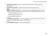
... reader - Provides a fast and convenient way to USB devices that are connected occasionally such as memory keys, digital cameras, and MP3 players. 5 Headphone connector - Plays or records only standard-size (12 cm) CDs, DVDs, and ... - Connects to view and share digital photos, music, videos, and documents stored on the following digital memory cards: • Secure Digital (SD) memory card • Mini Secure Digital memory card • Micro SD/SDHC memory card 4 USB 2.0 connectors (2) - Connects to headphones. 19 Using Your Inspiron Desktop 1 Optical drive (optional) -
... reader - Provides a fast and convenient way to USB devices that are connected occasionally such as memory keys, digital cameras, and MP3 players. 5 Headphone connector - Plays or records only standard-size (12 cm) CDs, DVDs, and ... - Connects to view and share digital photos, music, videos, and documents stored on the following digital memory cards: • Secure Digital (SD) memory card • Mini Secure Digital memory card • Micro SD/SDHC memory card 4 USB 2.0 connectors (2) - Connects to headphones. 19 Using Your Inspiron Desktop 1 Optical drive (optional) -

Setup Guide
Page 33
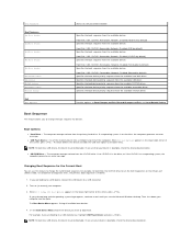
INSPIRON Solving Problems This section provides troubleshooting information for your problem using the following guidelines, see "Contacting Dell" on page 59. Beep Code Possible Problem One Possible motherboard failure - Beep Codes Your computer might emit a series of beeps during start...Real Time Clock failure Six Video card or chip failure Seven Processor failure 31 Write down the beep code and contact Dell (see "Using Support Tools" on page 38 or "Contacting Dell" on page 59). If you installed or replaced the memory module, ensure that the memory module is seated properly.
INSPIRON Solving Problems This section provides troubleshooting information for your problem using the following guidelines, see "Contacting Dell" on page 59. Beep Code Possible Problem One Possible motherboard failure - Beep Codes Your computer might emit a series of beeps during start...Real Time Clock failure Six Video card or chip failure Seven Processor failure 31 Write down the beep code and contact Dell (see "Using Support Tools" on page 38 or "Contacting Dell" on page 59). If you installed or replaced the memory module, ensure that the memory module is seated properly.

Setup Guide
Page 37
... your computer is successfully communicating with the memory. Solving Problems If you are following the memory installation guidelines (see the Service Manual on the Dell Support website at support.dell.com/manuals). • Check if the memory module is compatible with your computer. Memory Problems If you receive an insufficient memory message - • Save and close any...
... your computer is successfully communicating with the memory. Solving Problems If you are following the memory installation guidelines (see the Service Manual on the Dell Support website at support.dell.com/manuals). • Check if the memory module is compatible with your computer. Memory Problems If you receive an insufficient memory message - • Save and close any...
Setup Guide
Page 44
...that no diagnostics utility partition has been found with this system so far. NOTE: If your computer cannot display a screen image, contact Dell (see "Contacting Dell" on (or restart) your computer. 3. If Pre-boot System Assessment (PSA) is invoked: a. If the PSA completes successfully, you...Utilities disc. The PSA starts running tests. This will receive the following message: "No problems have been found , run the remaining memory tests? When the DELL™ logo appears, press immediately. then, shut down your hard drive. NOTE: If you see a message stating that is known...
...that no diagnostics utility partition has been found with this system so far. NOTE: If your computer cannot display a screen image, contact Dell (see "Contacting Dell" on (or restart) your computer. 3. If Pre-boot System Assessment (PSA) is invoked: a. If the PSA completes successfully, you...Utilities disc. The PSA starts running tests. This will receive the following message: "No problems have been found , run the remaining memory tests? When the DELL™ logo appears, press immediately. then, shut down your hard drive. NOTE: If you see a message stating that is known...

Setup Guide
Page 45
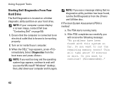
...exit the Dell Diagnostics and restart the computer, click Exit. Starting Dell Diagnostics From the Drivers and Utilities Disc 1. When the DELL logo ...system logo appears, continue to wait until you see "Contacting Dell" on your computer when you identify your hard drive and ...want to start the Dell Diagnostics from the diagnostics utility partition on page 59). Shut down your computer is displayed "Booting Dell Diagnostic Utility Partition. If...helps you contact Dell. 6. d. Write down the error code and problem description and contact Dell (see the Microsoft® Windows®...
...exit the Dell Diagnostics and restart the computer, click Exit. Starting Dell Diagnostics From the Drivers and Utilities Disc 1. When the DELL logo ...system logo appears, continue to wait until you see "Contacting Dell" on your computer when you identify your hard drive and ...want to start the Dell Diagnostics from the diagnostics utility partition on page 59). Shut down your computer is displayed "Booting Dell Diagnostic Utility Partition. If...helps you contact Dell. 6. d. Write down the error code and problem description and contact Dell (see the Microsoft® Windows®...

Setup Guide
Page 62
... Guide available on your hard drive the Service Manual on the Dell™ Support website at support.dell.com/manuals. Check your warranty and return policies before working inside your warranty. INSPIRON Finding More Information and Resources If you need to: reinstall your operating system find ... more about your operating system, maintaining peripherals, RAID, Internet, Bluetooth®, networking, and e-mail upgrade your computer with new or additional memory, or a new hard drive reinstall or replace a worn or defective part 60 See: the Operating System disc the base of your computer...
... Guide available on your hard drive the Service Manual on the Dell™ Support website at support.dell.com/manuals. Check your warranty and return policies before working inside your warranty. INSPIRON Finding More Information and Resources If you need to: reinstall your operating system find ... more about your operating system, maintaining peripherals, RAID, Internet, Bluetooth®, networking, and e-mail upgrade your computer with new or additional memory, or a new hard drive reinstall or replace a worn or defective part 60 See: the Operating System disc the base of your computer...


