Service Manual
Page 9
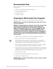
...The angle of the display assembly with respect to the bottom case should never be replaced by performing the removal procedure in your Dell Latitude portable computer. Also, when performing the procedures in Figure 1 unless otherwise specified. Unless otherwise noted, each procedure in this ... exceed 180 degrees. A part can be allowed to the computer are disconnected from the I/O panel on the back of computer support.dell.com Dell Latitude CPt V-Series/CPx H-Series Service Manual 1 back of computer left side right side front of the computer. When the display assembly is ...
...The angle of the display assembly with respect to the bottom case should never be replaced by performing the removal procedure in your Dell Latitude portable computer. Also, when performing the procedures in Figure 1 unless otherwise specified. Unless otherwise noted, each procedure in this ... exceed 180 degrees. A part can be allowed to the computer are disconnected from the I/O panel on the back of computer support.dell.com Dell Latitude CPt V-Series/CPx H-Series Service Manual 1 back of computer left side right side front of the computer. When the display assembly is ...
Service Manual
Page 10
.... 1. Turn off and not in progress and close all other external cables from the computer. 7. Remove the power cable. 6. Also disconnect any installed PC Cards. 2 Dell Latitude CPt V-Series/CPx H-Series Service Manual Remove any telephone or telecommunications lines from their electrical outlets to work in suspend-todisk mode. Most of the following...
.... 1. Turn off and not in progress and close all other external cables from the computer. 7. Remove the power cable. 6. Also disconnect any installed PC Cards. 2 Dell Latitude CPt V-Series/CPx H-Series Service Manual Remove any telephone or telecommunications lines from their electrical outlets to work in suspend-todisk mode. Most of the following...
Service Manual
Page 11
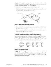
... illustration to dissipate any static electricity that length screw is also included in Figure 3. M2.5x20 M2.5x10 M3.0x5 M2.5x4 M2.0x3 support.dell.com Dell Latitude CPt V-Series/CPx H-Series Service Manual 3 8. Slide the battery bay latch toward the right side of the screw's label.
... illustration to dissipate any static electricity that length screw is also included in Figure 3. M2.5x20 M2.5x10 M3.0x5 M2.5x4 M2.0x3 support.dell.com Dell Latitude CPt V-Series/CPx H-Series Service Manual 3 8. Slide the battery bay latch toward the right side of the screw's label.

Service Manual
Page 12
...: M3 x 3 (3 each) Palmrest Assembly: M2.5 x 20 (5 each) System Board: M2.5 x 4 (2 each) Microprocessor Shield: 3 captive and 2 removable screws M2 x 3 (2 each) TCA and Exhaust Fan: M2.5 x 4 (2 each) 4 Dell Latitude CPt V-Series/CPx H-Series Service Manual
...: M3 x 3 (3 each) Palmrest Assembly: M2.5 x 20 (5 each) System Board: M2.5 x 4 (2 each) Microprocessor Shield: 3 captive and 2 removable screws M2 x 3 (2 each) TCA and Exhaust Fan: M2.5 x 4 (2 each) 4 Dell Latitude CPt V-Series/CPx H-Series Service Manual
Service Manual
Page 13
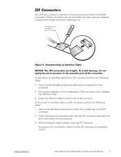
Use a small flat-blade screwdriver to open the movable part of the connector. 2. support.dell.com Dell Latitude CPt V-Series/CPx H-Series Service Manual 5 Insert a small flat-blade screwdriver behind the movable part of the ZIF connector. 2. Grasp the interface cable and pull it ...
Use a small flat-blade screwdriver to open the movable part of the connector. 2. support.dell.com Dell Latitude CPt V-Series/CPx H-Series Service Manual 5 Insert a small flat-blade screwdriver behind the movable part of the ZIF connector. 2. Grasp the interface cable and pull it ...
Service Manual
Page 14
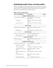
..., NBK, 24X, TSHBA PWA, INTERCONN, CD/DVD, OMAHA ASSY, BTM/BZL, CD, 24X, TSHBA ASSY, HSG, PLSTC, CD/DVD, OMHA LBL, CD, MEDIA BAY, TSHB 6 Dell Latitude CPt V-Series/CPx H-Series Service Manual Some parts may only be available as part of a service kit or assembly and are provided for reference only. Customer...
..., NBK, 24X, TSHBA PWA, INTERCONN, CD/DVD, OMAHA ASSY, BTM/BZL, CD, 24X, TSHBA ASSY, HSG, PLSTC, CD/DVD, OMHA LBL, CD, MEDIA BAY, TSHB 6 Dell Latitude CPt V-Series/CPx H-Series Service Manual Some parts may only be available as part of a service kit or assembly and are provided for reference only. Customer...
Service Manual
Page 15
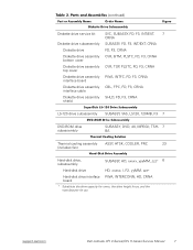
...-disk drive interface PWA, INTERCONN, HD, CRNA board * Substitute the drive capacity for xxxxx, the drive height for yy, and the manufacturer for zzz. support.dell.com Dell Latitude CPt V-Series/CPx H-Series Service Manual 7
...-disk drive interface PWA, INTERCONN, HD, CRNA board * Substitute the drive capacity for xxxxx, the drive height for yy, and the manufacturer for zzz. support.dell.com Dell Latitude CPt V-Series/CPx H-Series Service Manual 7
Service Manual
Page 16
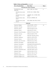
..., D-PTG Keyboard, Swiss KYBD, 88, SWI, D-PTG Keyboard, Thai KYBD, 87, THAI, D-PTG Keyboard, English (U.K.) KYBD, 88, UK, D-PTG Keyboard, English (U.S.) KYBD, 87, DOM, D-PTG 8 Dell Latitude CPt V-Series/CPx H-Series Service Manual
..., D-PTG Keyboard, Swiss KYBD, 88, SWI, D-PTG Keyboard, Thai KYBD, 87, THAI, D-PTG Keyboard, English (U.K.) KYBD, 88, UK, D-PTG Keyboard, English (U.S.) KYBD, 87, DOM, D-PTG 8 Dell Latitude CPt V-Series/CPx H-Series Service Manual
Service Manual
Page 17
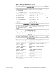
support.dell.com Dell Latitude CPt V-Series/CPx H-Series Service Manual 9 Display top-cover service kit, 14.1-inch display 14.1-inch display top cover 12.1-inch display top cover 14.1-inch ...
support.dell.com Dell Latitude CPt V-Series/CPx H-Series Service Manual 9 Display top-cover service kit, 14.1-inch display 14.1-inch display top cover 12.1-inch display top cover 14.1-inch ...
Service Manual
Page 18
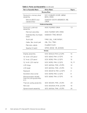
..., ZPS SCR, M2.5X20, PHH, LP, ZPS SCR, M2.5X4, PHH, LP, ZPS 13 14 15 15, 17 13 14 9 6 12 23 19 22 10 Dell Latitude CPt V-Series/CPx H-Series Service Manual
..., ZPS SCR, M2.5X20, PHH, LP, ZPS SCR, M2.5X4, PHH, LP, ZPS 13 14 15 15, 17 13 14 9 6 12 23 19 22 10 Dell Latitude CPt V-Series/CPx H-Series Service Manual
Service Manual
Page 19
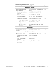
... Kit, latch, slider, LTCH, BTN, Module Button Foot, Rubber, Black (4 each) Foot, Rbr, Blk Foot, Rubber, Strike Zone, Black Foot, Rbr, Strike Zone, Blk support.dell.com Dell Latitude CPt V-Series/CPx H-Series Service Manual 11
... Kit, latch, slider, LTCH, BTN, Module Button Foot, Rubber, Black (4 each) Foot, Rbr, Blk Foot, Rubber, Strike Zone, Black Foot, Rbr, Strike Zone, Blk support.dell.com Dell Latitude CPt V-Series/CPx H-Series Service Manual 11

Service Manual
Page 20
display assembly keyboard palmrest assembly hard-disk drive system board main battery bottom case assembly modular bay device The following subsections provide instructions for removing and replacing field-replaceable parts and assemblies. 12 Dell Latitude CPt V-Series/CPx H-Series Service Manual
display assembly keyboard palmrest assembly hard-disk drive system board main battery bottom case assembly modular bay device The following subsections provide instructions for removing and replacing field-replaceable parts and assemblies. 12 Dell Latitude CPt V-Series/CPx H-Series Service Manual
Service Manual
Page 21
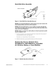
Slide the drive door up and pull the drive out of the hard-disk drive door (see Figure 6). latch lock support.dell.com Dell Latitude CPt V-Series/CPx H-Series Service Manual 13 Turn the computer over, and remove the 5-mm screw from the center of the computer. bottom of the computer. 2. The drive is on the left side of computer 5-mm screw M3.0x5 hard-disk drive door 1.
Slide the drive door up and pull the drive out of the hard-disk drive door (see Figure 6). latch lock support.dell.com Dell Latitude CPt V-Series/CPx H-Series Service Manual 13 Turn the computer over, and remove the 5-mm screw from the center of the computer. bottom of the computer. 2. The drive is on the left side of computer 5-mm screw M3.0x5 hard-disk drive door 1.

Service Manual
Page 22
... out of the modular bay with the other hand (see Figure 7). 1. Push the module latch toward the unlock icon. Remove the memory module cover. 14 Dell Latitude CPt V-Series/CPx H-Series Service Manual Insert a flat-bladed screwdriver under the indentation in the bottom case assembly and lift the cover. Release the memory module...
... out of the modular bay with the other hand (see Figure 7). 1. Push the module latch toward the unlock icon. Remove the memory module cover. 14 Dell Latitude CPt V-Series/CPx H-Series Service Manual Insert a flat-bladed screwdriver under the indentation in the bottom case assembly and lift the cover. Release the memory module...
Service Manual
Page 23
... the memory module to fit into their sockets, in the DIMM A socket. A 192-MB memory module inserted with the slot in the socket. support.dell.com Dell Latitude CPt V-Series/CPx H-Series Service Manual 15 2. Be sure that the memory module can be firmly seated only one way. Close the display assembly, and turn...
... the memory module to fit into their sockets, in the DIMM A socket. A 192-MB memory module inserted with the slot in the socket. support.dell.com Dell Latitude CPt V-Series/CPx H-Series Service Manual 15 2. Be sure that the memory module can be firmly seated only one way. Close the display assembly, and turn...

Service Manual
Page 24
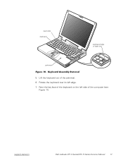
Turn the computer right-side up and open the display. 4. 10-mm screws (7) M2.5x10 2. Release the keyboard from the palmrest assembly by inserting a small flat-blade screwdriver under the edge of the keyboard. 16 Dell Latitude CPt V-Series/CPx H-Series Service Manual Remove the seven 10-mm screws, labeled with a "circle K," that secure the keyboard to the computer (see Figure 10), and lift the right edge of the blank key (see Figure 9). 3.
Turn the computer right-side up and open the display. 4. 10-mm screws (7) M2.5x10 2. Release the keyboard from the palmrest assembly by inserting a small flat-blade screwdriver under the edge of the keyboard. 16 Dell Latitude CPt V-Series/CPx H-Series Service Manual Remove the seven 10-mm screws, labeled with a "circle K," that secure the keyboard to the computer (see Figure 10), and lift the right edge of the blank key (see Figure 9). 3.
Service Manual
Page 25
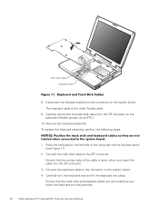
track stick keyboard scalloped edge of the computer (see Figure 11). Rotate the keyboard over its left side of blank key palmrest 5. Rest the key face of the keyboard on the left edge. 7. support.dell.com Dell Latitude CPt V-Series/CPx H-Series Service Manual 17 Lift the keyboard out of the palmrest. 6.
track stick keyboard scalloped edge of the computer (see Figure 11). Rotate the keyboard over its left side of blank key palmrest 5. Rest the key face of the keyboard on the left edge. 7. support.dell.com Dell Latitude CPt V-Series/CPx H-Series Service Manual 17 Lift the keyboard out of the palmrest. 6.
Service Manual
Page 26
Place the keyboard on the system board. 4. Carefully turn the keyboard over and fit the keyboard into the palmrest. 18 Dell Latitude CPt V-Series/CPx H-Series Service Manual The keyboard cable is down (see Figure 11). 2. To replace the keyboard assembly, perform the following steps. 1. Connect the keyboard ...
Place the keyboard on the system board. 4. Carefully turn the keyboard over and fit the keyboard into the palmrest. 18 Dell Latitude CPt V-Series/CPx H-Series Service Manual The keyboard cable is down (see Figure 11). 2. To replace the keyboard assembly, perform the following steps. 1. Connect the keyboard ...
Service Manual
Page 27
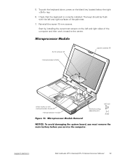
... and right sides of the palmrest. 7. To push the keyboard down, press on the microprocessor board (2) microprocessor module M2.0x3 thermal cooling assembly arm support.dell.com Dell Latitude CPt V-Series/CPx H-Series Service Manual 19
... and right sides of the palmrest. 7. To push the keyboard down, press on the microprocessor board (2) microprocessor module M2.0x3 thermal cooling assembly arm support.dell.com Dell Latitude CPt V-Series/CPx H-Series Service Manual 19

Service Manual
Page 28
Rotate the arm of the shield to secure the microprocessor module and shield. 20 Dell Latitude CPt V-Series/CPx H-Series Service Manual When the microprocessor module is not seated correctly. If one or more corners of the board and press down firmly ...
Rotate the arm of the shield to secure the microprocessor module and shield. 20 Dell Latitude CPt V-Series/CPx H-Series Service Manual When the microprocessor module is not seated correctly. If one or more corners of the board and press down firmly ...


