
Service Manual
Page 8
Throughout this manual, Dell provides the User's Guide for using the Dell Diagnostics to test the computer system. These blocks are notes, notices, and cautions, and they are used as follows: NOTE: A NOTE indicates important information that ... be accompanied by an icon and printed in bold type or in PC troubleshooting techniques. viii A prerequisite for troubleshooting procedures and instructions on using this manual to service Dell computer systems is a basic knowledge of PCs and prior training in italic type.
Throughout this manual, Dell provides the User's Guide for using the Dell Diagnostics to test the computer system. These blocks are notes, notices, and cautions, and they are used as follows: NOTE: A NOTE indicates important information that ... be accompanied by an icon and printed in bold type or in PC troubleshooting techniques. viii A prerequisite for troubleshooting procedures and instructions on using this manual to service Dell computer systems is a basic knowledge of PCs and prior training in italic type.
Service Manual
Page 9
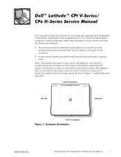
... support.dell.com Dell Latitude CPt V-Series/CPx H-Series Service Manual 1 Also, when performing the procedures in this manual assumes the following conditions: The computer and any attached peripherals are turned off, and the peripherals are as shown in this manual, the... to the computer are disconnected from the I/O panel on the back of the computer. This manual provides instructions for removing and replacing field-replaceable components, assemblies, and subassemblies in reverse order. ... replaced by performing the removal procedure in your Dell Latitude portable computer.
... support.dell.com Dell Latitude CPt V-Series/CPx H-Series Service Manual 1 Also, when performing the procedures in this manual assumes the following conditions: The computer and any attached peripherals are turned off, and the peripherals are as shown in this manual, the... to the computer are disconnected from the I/O panel on the back of the computer. This manual provides instructions for removing and replacing field-replaceable components, assemblies, and subassemblies in reverse order. ... replaced by performing the removal procedure in your Dell Latitude portable computer.
Service Manual
Page 10
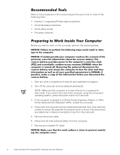
... in a C/Dock Family Expansion Station or C/Port Family Advanced Port Replicator (APR), undock the computer. 4. Remove any attached peripherals. Most of the procedures in this manual require the use of one or more of the following steps. 1. Turn off and not in progress and close all other external cables from the... computer's operating system, press the power button for personal injury or shock. If the computer is turned off the computer and any installed PC Cards. 2 Dell Latitude CPt V-Series/CPx H-Series Service Manual
... in a C/Dock Family Expansion Station or C/Port Family Advanced Port Replicator (APR), undock the computer. 4. Remove any attached peripherals. Most of the procedures in this manual require the use of one or more of the following steps. 1. Turn off and not in progress and close all other external cables from the... computer's operating system, press the power button for personal injury or shock. If the computer is turned off the computer and any installed PC Cards. 2 Dell Latitude CPt V-Series/CPx H-Series Service Manual
Service Manual
Page 11
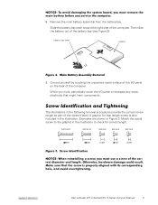
... battery bay latch toward the right side of the computer. battery bay latch battery 9. M2.5x20 M2.5x10 M3.0x5 M2.5x4 M2.0x3 support.dell.com Dell Latitude CPt V-Series/CPx H-Series Service Manual 3 A graphic for correct length.
... battery bay latch toward the right side of the computer. battery bay latch battery 9. M2.5x20 M2.5x10 M3.0x5 M2.5x4 M2.0x3 support.dell.com Dell Latitude CPt V-Series/CPx H-Series Service Manual 3 A graphic for correct length.

Service Manual
Page 12
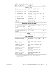
...) Display Assembly Bezel: Rubber Screw Covers (4 each) Plastic Screw Covers (2 each) Display Assembly Bezel: M2.5 x 4 (6 each) 14.1 Display Assembly LCD to Top Cover: M2 x 3 (6 each ) 4 Dell Latitude CPt V-Series/CPx H-Series Service Manual
...) Display Assembly Bezel: Rubber Screw Covers (4 each) Plastic Screw Covers (2 each) Display Assembly Bezel: M2.5 x 4 (6 each) 14.1 Display Assembly LCD to Top Cover: M2 x 3 (6 each ) 4 Dell Latitude CPt V-Series/CPx H-Series Service Manual
Service Manual
Page 13
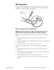
... be released to disconnect a cable from a ZIF connector, perform the following steps: 1. While holding the cable in place, close the ZIF connector. support.dell.com Dell Latitude CPt V-Series/CPx H-Series Service Manual 5 Use a small flat-blade screwdriver to a ZIF connector, perform the following steps: 1. Push gently sideways on the movable part of the cable...
... be released to disconnect a cable from a ZIF connector, perform the following steps: 1. While holding the cable in place, close the ZIF connector. support.dell.com Dell Latitude CPt V-Series/CPx H-Series Service Manual 5 Use a small flat-blade screwdriver to a ZIF connector, perform the following steps: 1. Push gently sideways on the movable part of the cable...
Service Manual
Page 14
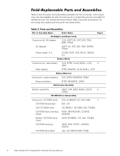
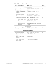
..., NBK, 24X, TSHBA PWA, INTERCONN, CD/DVD, OMAHA ASSY, BTM/BZL, CD, 24X, TSHBA ASSY, HSG, PLSTC, CD/DVD, OMHA LBL, CD, MEDIA BAY, TSHB 6 Dell Latitude CPt V-Series/CPx H-Series Service Manual
..., NBK, 24X, TSHBA PWA, INTERCONN, CD/DVD, OMAHA ASSY, BTM/BZL, CD, 24X, TSHBA ASSY, HSG, PLSTC, CD/DVD, OMHA LBL, CD, MEDIA BAY, TSHB 6 Dell Latitude CPt V-Series/CPx H-Series Service Manual
Service Manual
Page 15
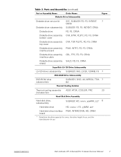
...-disk drive interface PWA, INTERCONN, HD, CRNA board * Substitute the drive capacity for xxxxx, the drive height for yy, and the manufacturer for zzz. support.dell.com Dell Latitude CPt V-Series/CPx H-Series Service Manual 7
...-disk drive interface PWA, INTERCONN, HD, CRNA board * Substitute the drive capacity for xxxxx, the drive height for yy, and the manufacturer for zzz. support.dell.com Dell Latitude CPt V-Series/CPx H-Series Service Manual 7
Service Manual
Page 16
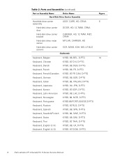
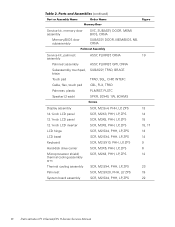
..., D-PTG Keyboard, Swiss KYBD, 88, SWI, D-PTG Keyboard, Thai KYBD, 87, THAI, D-PTG Keyboard, English (U.K.) KYBD, 88, UK, D-PTG Keyboard, English (U.S.) KYBD, 87, DOM, D-PTG 8 Dell Latitude CPt V-Series/CPx H-Series Service Manual
..., D-PTG Keyboard, Swiss KYBD, 88, SWI, D-PTG Keyboard, Thai KYBD, 87, THAI, D-PTG Keyboard, English (U.K.) KYBD, 88, UK, D-PTG Keyboard, English (U.S.) KYBD, 87, DOM, D-PTG 8 Dell Latitude CPt V-Series/CPx H-Series Service Manual
Service Manual
Page 17
support.dell.com Dell Latitude CPt V-Series/CPx H-Series Service Manual 9 Display top-cover service kit, 14.1-inch display 14.1-inch display top cover 12.1-inch display top cover 14.1-inch flex cable 12.1-inch flex ...
support.dell.com Dell Latitude CPt V-Series/CPx H-Series Service Manual 9 Display top-cover service kit, 14.1-inch display 14.1-inch display top cover 12.1-inch display top cover 14.1-inch flex cable 12.1-inch flex ...
Service Manual
Page 18
..., ZPS SCR, M2.5X20, PHH, LP, ZPS SCR, M2.5X4, PHH, LP, ZPS 13 14 15 15, 17 13 14 9 6 12 23 19 22 10 Dell Latitude CPt V-Series/CPx H-Series Service Manual
..., ZPS SCR, M2.5X20, PHH, LP, ZPS SCR, M2.5X4, PHH, LP, ZPS 13 14 15 15, 17 13 14 9 6 12 23 19 22 10 Dell Latitude CPt V-Series/CPx H-Series Service Manual
Service Manual
Page 19
... Kit, latch, slider, LTCH, BTN, Module Button Foot, Rubber, Black (4 each) Foot, Rbr, Blk Foot, Rubber, Strike Zone, Black Foot, Rbr, Strike Zone, Blk support.dell.com Dell Latitude CPt V-Series/CPx H-Series Service Manual 11
... Kit, latch, slider, LTCH, BTN, Module Button Foot, Rubber, Black (4 each) Foot, Rbr, Blk Foot, Rubber, Strike Zone, Black Foot, Rbr, Strike Zone, Blk support.dell.com Dell Latitude CPt V-Series/CPx H-Series Service Manual 11

Service Manual
Page 20
display assembly keyboard palmrest assembly hard-disk drive system board main battery bottom case assembly modular bay device The following subsections provide instructions for removing and replacing field-replaceable parts and assemblies. 12 Dell Latitude CPt V-Series/CPx H-Series Service Manual
display assembly keyboard palmrest assembly hard-disk drive system board main battery bottom case assembly modular bay device The following subsections provide instructions for removing and replacing field-replaceable parts and assemblies. 12 Dell Latitude CPt V-Series/CPx H-Series Service Manual
Service Manual
Page 21
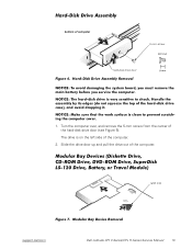
The drive is on the left side of the hard-disk drive door (see Figure 6). Turn the computer over, and remove the 5-mm screw from the center of the computer. 2. latch lock support.dell.com Dell Latitude CPt V-Series/CPx H-Series Service Manual 13 bottom of the computer. Slide the drive door up and pull the drive out of computer 5-mm screw M3.0x5 hard-disk drive door 1.
The drive is on the left side of the hard-disk drive door (see Figure 6). Turn the computer over, and remove the 5-mm screw from the center of the computer. 2. latch lock support.dell.com Dell Latitude CPt V-Series/CPx H-Series Service Manual 13 bottom of the computer. Slide the drive door up and pull the drive out of computer 5-mm screw M3.0x5 hard-disk drive door 1.

Service Manual
Page 22
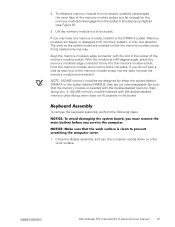
... holding the latch open while pulling the device out of the modular bay with the other hand (see Figure 7). 1. 1. Remove the memory module cover. 14 Dell Latitude CPt V-Series/CPx H-Series Service Manual
... holding the latch open while pulling the device out of the modular bay with the other hand (see Figure 7). 1. 1. Remove the memory module cover. 14 Dell Latitude CPt V-Series/CPx H-Series Service Manual
Service Manual
Page 23
... the double-stacked memory chips facing you only have one direction. A 192-MB memory module inserted with the slot in the socket. support.dell.com Dell Latitude CPt V-Series/CPx H-Series Service Manual 15 With the module at a 45-degree angle, press the memory module's edge connector firmly into their sockets, in the DIMM A socket...
... the double-stacked memory chips facing you only have one direction. A 192-MB memory module inserted with the slot in the socket. support.dell.com Dell Latitude CPt V-Series/CPx H-Series Service Manual 15 With the module at a 45-degree angle, press the memory module's edge connector firmly into their sockets, in the DIMM A socket...

Service Manual
Page 24
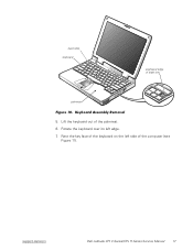
Turn the computer right-side up and open the display. 4. Release the keyboard from the palmrest assembly by inserting a small flat-blade screwdriver under the edge of the keyboard. 16 Dell Latitude CPt V-Series/CPx H-Series Service Manual 10-mm screws (7) M2.5x10 2. Remove the seven 10-mm screws, labeled with a "circle K," that secure the keyboard to the computer (see Figure 10), and lift the right edge of the blank key (see Figure 9). 3.
Turn the computer right-side up and open the display. 4. Release the keyboard from the palmrest assembly by inserting a small flat-blade screwdriver under the edge of the keyboard. 16 Dell Latitude CPt V-Series/CPx H-Series Service Manual 10-mm screws (7) M2.5x10 2. Remove the seven 10-mm screws, labeled with a "circle K," that secure the keyboard to the computer (see Figure 10), and lift the right edge of the blank key (see Figure 9). 3.
Service Manual
Page 25
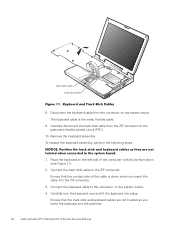
Rest the key face of the computer (see Figure 11). support.dell.com Dell Latitude CPt V-Series/CPx H-Series Service Manual 17 Rotate the keyboard over its left side of the keyboard on the left edge. 7. track stick keyboard scalloped edge of the palmrest. 6. Lift the keyboard out of blank key palmrest 5.
Rest the key face of the computer (see Figure 11). support.dell.com Dell Latitude CPt V-Series/CPx H-Series Service Manual 17 Rotate the keyboard over its left side of the keyboard on the left edge. 7. track stick keyboard scalloped edge of the palmrest. 6. Lift the keyboard out of blank key palmrest 5.
Service Manual
Page 26
... steps. 1. Ensure that the contact side of the computer with its key face down when you lower the keyboard into the palmrest. 18 Dell Latitude CPt V-Series/CPx H-Series Service Manual Connect the track stick cable to the connector on the left side of the cable is the wide, flexible cable. 9. Connect the keyboard...
... steps. 1. Ensure that the contact side of the computer with its key face down when you lower the keyboard into the palmrest. 18 Dell Latitude CPt V-Series/CPx H-Series Service Manual Connect the track stick cable to the connector on the left side of the cable is the wide, flexible cable. 9. Connect the keyboard...
Service Manual
Page 27
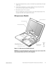
... center. 3-mm screws (2) microprocessor shield captive screws (3) white marks on the microprocessor board (2) microprocessor module M2.0x3 thermal cooling assembly arm support.dell.com Dell Latitude CPt V-Series/CPx H-Series Service Manual 19 Start by installing the outermost screws on the blank key located below the right key. 6. Reinstall the seven 10-mm screws. Check...
... center. 3-mm screws (2) microprocessor shield captive screws (3) white marks on the microprocessor board (2) microprocessor module M2.0x3 thermal cooling assembly arm support.dell.com Dell Latitude CPt V-Series/CPx H-Series Service Manual 19 Start by installing the outermost screws on the blank key located below the right key. 6. Reinstall the seven 10-mm screws. Check...


