Dell Owners Manual
Page 4
... Bezel...42 Removing the Display Panel...42 Installing the Display Panel...44 Removing the Display Hinges...44 Installing the Display Hinges...45 Removing the Camera...45 Installing the Camera...46 3 System Setup...47 Boot Sequence...47 Navigation Keys...47 System Setup Options...48 Updating the BIOS ...57 System and Setup Password...57...
... Bezel...42 Removing the Display Panel...42 Installing the Display Panel...44 Removing the Display Hinges...44 Installing the Display Hinges...45 Removing the Camera...45 Installing the Camera...46 3 System Setup...47 Boot Sequence...47 Navigation Keys...47 System Setup Options...48 Updating the BIOS ...57 System and Setup Password...57...
Dell Owners Manual
Page 26
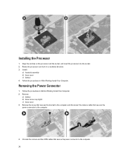
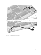
.... 2. Install: a) heatsink assembly b) base cover c) battery 4. Remove: a) battery b) base corner cap (right) c) base cover 3. Follow the procedures in After Working Inside Your Computer. Unroute the camera and the LVDS cables that secures the power connector to the computer. 26 Remove the screw that secures the bracket to the computer and disconnect...
.... 2. Install: a) heatsink assembly b) base cover c) battery 4. Remove: a) battery b) base corner cap (right) c) base cover 3. Follow the procedures in After Working Inside Your Computer. Unroute the camera and the LVDS cables that secures the power connector to the computer. 26 Remove the screw that secures the bracket to the computer and disconnect...
Dell Owners Manual
Page 27
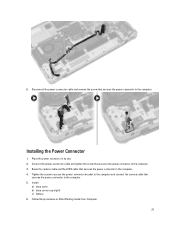
Route the camera cable and the LVDS cable that secures the power connector to the computer. 4. Install: a) base cover b) base corner cap (right) c) battery 6. Place the power connector ... the screw that secures the power connector to the computer. Tighten the screw to secure the power-connector bracket to the computer and connect the camera cable that secures the power connector to the computer. 5. Installing the Power Connector 1. 5.
Route the camera cable and the LVDS cable that secures the power connector to the computer. 4. Install: a) base cover b) base corner cap (right) c) battery 6. Place the power connector ... the screw that secures the power connector to the computer. Tighten the screw to secure the power-connector bracket to the computer and connect the camera cable that secures the power connector to the computer. 5. Installing the Power Connector 1. 5.
Dell Owners Manual
Page 39
Remove the display assembly from the routing channel. 5. Remove the screws that secure the display assembly to the computer. 4. Disconnect the LVDS cable and release the LVDS cable and camera cable from the computer. 39
Remove the display assembly from the routing channel. 5. Remove the screws that secure the display assembly to the computer. 4. Disconnect the LVDS cable and release the LVDS cable and camera cable from the computer. 39
Dell Owners Manual
Page 40
... the procedures in After Working Inside Your Computer. Connect wireless antennas along the edges to secure the display assembly. 3. Route the LVDS cable and the camera cable through the routing channel. Remove: a) battery b) display-hinge cap c) base cover d) base corner caps e) display assembly 3. Place the display assembly in its position on...
... the procedures in After Working Inside Your Computer. Connect wireless antennas along the edges to secure the display assembly. 3. Route the LVDS cable and the camera cable through the routing channel. Remove: a) battery b) display-hinge cap c) base cover d) base corner caps e) display assembly 3. Place the display assembly in its position on...
Dell Owners Manual
Page 45
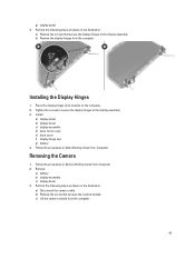
...2. Follow the procedures in the illustration: a) Remove the screws that secures the camera module. b) Remove the screw that secure the display hinges to the display assembly. 3. Removing the Camera 1. Perform the following steps as shown in Before Working Inside Your Computer. 2. ...: a) display panel b) display bezel c) display assembly d) base corner caps e) base cover f) display-hinge cap g) battery 4. c) Lift the camera module from the computer. b) Remove the display hinges from the computer. 45 g) display panel 3. Tighten the screws to secure the display hinges to...
...2. Follow the procedures in the illustration: a) Remove the screws that secures the camera module. b) Remove the screw that secure the display hinges to the display assembly. 3. Removing the Camera 1. Perform the following steps as shown in Before Working Inside Your Computer. 2. ...: a) display panel b) display bezel c) display assembly d) base corner caps e) base cover f) display-hinge cap g) battery 4. c) Lift the camera module from the computer. b) Remove the display hinges from the computer. 45 g) display panel 3. Tighten the screws to secure the display hinges to...
Dell Owners Manual
Page 46
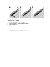
Install: a) display bezel b) display assembly c) battery 5. Tighten the screw to secure the camera to the display assembly. 3. Connect the camera cable. 4. Follow the procedures in the computer. 2. Installing the Camera 1. Place the camera module in its slot in After Working Inside Your Computer. 46
Install: a) display bezel b) display assembly c) battery 5. Tighten the screw to secure the camera to the display assembly. 3. Connect the camera cable. 4. Follow the procedures in the computer. 2. Installing the Camera 1. Place the camera module in its slot in After Working Inside Your Computer. 46
Dell Owners Manual
Page 51
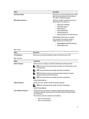
... the admin password automatically deletes the system password and the hard drive password. The options are: • Enable Internal Modem • Enable Microphone • Enable Camera • Enable Module Bay • Enable ExpressCard • Enable Hard Drive Free Fall Protection Default Setting: All devices are : • Enable Media Card (Default Setting...
... the admin password automatically deletes the system password and the hard drive password. The options are: • Enable Internal Modem • Enable Microphone • Enable Camera • Enable Module Bay • Enable ExpressCard • Enable Hard Drive Free Fall Protection Default Setting: All devices are : • Enable Media Card (Default Setting...
Dell Owners Manual
Page 64
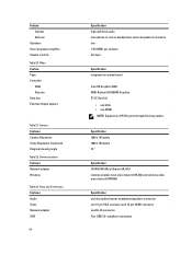
Camera Features Camera Resolution Video Resolution (maximum) Diagonal viewing angle Table 22. Ports and Connectors Features Audio Video Network adapter USB 64 Specification high-definition audio microphone-in, ...
Camera Features Camera Resolution Video Resolution (maximum) Diagonal viewing angle Table 22. Ports and Connectors Features Audio Video Network adapter USB 64 Specification high-definition audio microphone-in, ...
Dell Setup and Features Information
Page 1
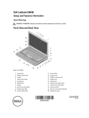
... switch 19. display latch 7. wireless status light 11. optical-drive eject button 18. power button 12. optical drive 16. Dell Latitude E6440 Setup and Features Information About Warnings WARNING: A WARNING indicates a potential for property damage, personal injury, or death. camera 4. headset port 15. Front View 1. hard-drive activity light 9. optical-drive release latch 17.
... switch 19. display latch 7. wireless status light 11. optical-drive eject button 18. power button 12. optical drive 16. Dell Latitude E6440 Setup and Features Information About Warnings WARNING: A WARNING indicates a potential for property damage, personal injury, or death. camera 4. headset port 15. Front View 1. hard-drive activity light 9. optical-drive release latch 17.


