
Dell Owners Manual
Page 3
... Hard Drive...15 Installing the Hard Drive...16 Removing the Optical Drive...16 Installing the Optical Drive...17 Removing the Keyboard Trim...17 Installing the Keyboard Trim...18 Removing the Keyboard...18 Installing the Keyboard...19 Removing the WLAN Card...20 Installing the WLAN Card...20 Removing the WWAN Card...20 Installing the WWAN...
... Hard Drive...15 Installing the Hard Drive...16 Removing the Optical Drive...16 Installing the Optical Drive...17 Removing the Keyboard Trim...17 Installing the Keyboard Trim...18 Removing the Keyboard...18 Installing the Keyboard...19 Removing the WLAN Card...20 Installing the WLAN Card...20 Removing the WWAN Card...20 Installing the WWAN...

Dell Owners Manual
Page 12
speakers 4. Press in on the SD card to release it clicks into its slot until it from the computer. Slide the SD card out of the computer. Figure 2. Top View - ExpressCard cage 3. I/O board Removing the Secure Digital (SD) Card 1. Installing the Secure Digital (SD) Card 1. WiFi-switch board 2. Follow the procedures in Before Working Inside Your Computer. 2. Follow the procedures in After Working Inside Your Computer. 12 hard-drive bay 5. system board 6. Keyboard and Palmrest Assembly removed 1. Slide the SD card into place. 2.
speakers 4. Press in on the SD card to release it clicks into its slot until it from the computer. Slide the SD card out of the computer. Figure 2. Top View - ExpressCard cage 3. I/O board Removing the Secure Digital (SD) Card 1. Installing the Secure Digital (SD) Card 1. WiFi-switch board 2. Follow the procedures in Before Working Inside Your Computer. 2. Follow the procedures in After Working Inside Your Computer. 12 hard-drive bay 5. system board 6. Keyboard and Palmrest Assembly removed 1. Slide the SD card into place. 2.
Dell Owners Manual
Page 17
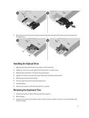
... optical-drive latch bracket. 4. Follow the procedures in After Working Inside Your Computer. Remove the latch bracket from the computer. Using a plastic scribe, pry the keyboard trim to release it up to secure the optical drive. 7. Align the optical-drive latch bracket to the optical drive. 3. Slide the optical drive into...
... optical-drive latch bracket. 4. Follow the procedures in After Working Inside Your Computer. Remove the latch bracket from the computer. Using a plastic scribe, pry the keyboard trim to release it up to secure the optical drive. 7. Align the optical-drive latch bracket to the optical drive. 3. Slide the optical drive into...

Dell Owners Manual
Page 18
Press along the sides of the computer and flip the computer. 18 Follow the procedures in After Working Inside Your Computer. Follow the procedures in Before Working Inside Your Computer. 2. Remove the screws on the back of the keyboard trim until it clicks in place. 3. Installing the Keyboard Trim 1. Install battery. 4. Remove the: a) battery b) keyboard trim 3. Removing the Keyboard 1. Align the keyboard trim to its slot. 2.
Press along the sides of the computer and flip the computer. 18 Follow the procedures in After Working Inside Your Computer. Follow the procedures in Before Working Inside Your Computer. 2. Remove the screws on the back of the keyboard trim until it clicks in place. 3. Installing the Keyboard Trim 1. Install battery. 4. Remove the: a) battery b) keyboard trim 3. Removing the Keyboard 1. Align the keyboard trim to its slot. 2.
Dell Owners Manual
Page 19
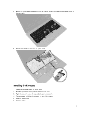
Tighten the screws to secure the keyboard to access the keyboard-cable. 5. Remove the screws that secure the keyboard to the palmrest assembly, lift and flip the keyboard to the palmrest assembly. 4. Slide the keyboard into its compartment until it clicks into place. 3. Install the battery. 19 4. Disconnect the keyboard cable from the system board. Installing the Keyboard 1. Connect the keyboard cable to the system board. 2. Flip the computer and tighten the screws on the back of the computer. 5. Install the keyboard trim. 6.
Tighten the screws to secure the keyboard to access the keyboard-cable. 5. Remove the screws that secure the keyboard to the palmrest assembly, lift and flip the keyboard to the palmrest assembly. 4. Slide the keyboard into its compartment until it clicks into place. 3. Install the battery. 19 4. Disconnect the keyboard cable from the system board. Installing the Keyboard 1. Connect the keyboard cable to the system board. 2. Flip the computer and tighten the screws on the back of the computer. 5. Install the keyboard trim. 6.

Dell Owners Manual
Page 28
... battery. 4. Remove the screws that secure the palmrest assembly to the base of the computer. 28 Remove the battery. 3. Remove: a) SD card b) ExpressCard c) battery d) keyboard trim e) keyboard f) hard drive g) optical drive h) display-hinge cover i) base cover j) base corner caps 3. Tighten the screws to secure the display-hinge cover to the computer and...
... battery. 4. Remove the screws that secure the palmrest assembly to the base of the computer. 28 Remove the battery. 3. Remove: a) SD card b) ExpressCard c) battery d) keyboard trim e) keyboard f) hard drive g) optical drive h) display-hinge cover i) base cover j) base corner caps 3. Tighten the screws to secure the display-hinge cover to the computer and...

Dell Owners Manual
Page 30
... the procedures in After Working Inside Your Computer. Remove: a) SD Card 30 Install: a) base corner caps b) base cover c) display-hinge cover d) optical drive e) hard drive f) keyboard g) keyboard trim h) battery i) ExpressCard j) SD card 6.
... the procedures in After Working Inside Your Computer. Remove: a) SD Card 30 Install: a) base corner caps b) base cover c) display-hinge cover d) optical drive e) hard drive f) keyboard g) keyboard trim h) battery i) ExpressCard j) SD card 6.
Dell Owners Manual
Page 31
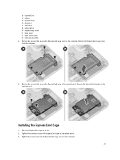
... the ExpressCard cage cover to the system board. 3. Installing the ExpressCard Cage 1. Tighten the screws to secure the ExpressCard cage to the computer. b) ExpressCard c) battery d) keyboard trim e) keyboard f) hard drive g) optical drive h) display-hinge cover i) base cover j) base corner caps k) palmrest assembly 3. Remove the ExpressCard cage from the computer. 4. Remove the screws...
... the ExpressCard cage cover to the system board. 3. Installing the ExpressCard Cage 1. Tighten the screws to secure the ExpressCard cage to the computer. b) ExpressCard c) battery d) keyboard trim e) keyboard f) hard drive g) optical drive h) display-hinge cover i) base cover j) base corner caps k) palmrest assembly 3. Remove the ExpressCard cage from the computer. 4. Remove the screws...

Dell Owners Manual
Page 32
... as shown in the illustration: a) Disconnect the WiFi-switch board cable from the computer. 32 Removing the WiFi-Switch Board 1. Remove: a) SD Card b) ExpressCard c) battery d) keyboard trim e) keyboard f) hard drive g) optical drive h) display-hinge cover i) base cover j) base corner caps k) palmrest assembly 3. Install: a) palmrest assembly b) base corner caps c) base cover d) display-hinge...
... as shown in the illustration: a) Disconnect the WiFi-switch board cable from the computer. 32 Removing the WiFi-Switch Board 1. Remove: a) SD Card b) ExpressCard c) battery d) keyboard trim e) keyboard f) hard drive g) optical drive h) display-hinge cover i) base cover j) base corner caps k) palmrest assembly 3. Install: a) palmrest assembly b) base corner caps c) base cover d) display-hinge...

Dell Owners Manual
Page 33
Install: a) palmrest assembly b) base cover c) base corner caps d) display-hinge cap e) optical drive f) hard drive g) keyboard h) keyboard trim i) battery j) ExpressCard k) SD Card 5. Follow the procedures in After Working Inside Your Computer. Remove: a) SD Card b) ExpressCard c) battery d) keyboard trim e) keyboard f) hard drive g) optical drive h) display-hinge cover i) base cover j) base corner caps k) power connector l) coin-cell...
Install: a) palmrest assembly b) base cover c) base corner caps d) display-hinge cap e) optical drive f) hard drive g) keyboard h) keyboard trim i) battery j) ExpressCard k) SD Card 5. Follow the procedures in After Working Inside Your Computer. Remove: a) SD Card b) ExpressCard c) battery d) keyboard trim e) keyboard f) hard drive g) optical drive h) display-hinge cover i) base cover j) base corner caps k) power connector l) coin-cell...
Dell Owners Manual
Page 35
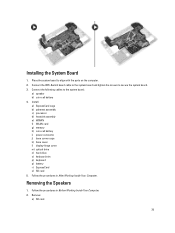
... c) processor d) heatsink assembly e) WWAN f) WLAN card g) memory h) coin-cell battery i) power connector j) base corner caps k) base cover l) display-hinge cover m) optical drive n) hard drive o) keyboard trim p) keyboard q) battery r) ExpressCard s) SD card 5. Follow the procedures in After Working Inside Your Computer. Connect the following cables to secure the system board. 3. Follow the procedures...
... c) processor d) heatsink assembly e) WWAN f) WLAN card g) memory h) coin-cell battery i) power connector j) base corner caps k) base cover l) display-hinge cover m) optical drive n) hard drive o) keyboard trim p) keyboard q) battery r) ExpressCard s) SD card 5. Follow the procedures in After Working Inside Your Computer. Connect the following cables to secure the system board. 3. Follow the procedures...
Dell Owners Manual
Page 36
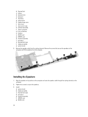
... the Speakers 1. Align the speakers in its position on the computer and route the speaker cable through the routing channels on the computer. 2. b) ExpressCard c) battery d) keyboard trim e) keyboard f) hard drive g) optical drive h) display-hinge cover i) base cover j) base corner caps k) palmrest assembly l) power connector m) coin-cell battery n) memory o) WLAN card p) WWAN card...
... the Speakers 1. Align the speakers in its position on the computer and route the speaker cable through the routing channels on the computer. 2. b) ExpressCard c) battery d) keyboard trim e) keyboard f) hard drive g) optical drive h) display-hinge cover i) base cover j) base corner caps k) palmrest assembly l) power connector m) coin-cell battery n) memory o) WLAN card p) WWAN card...
Dell Owners Manual
Page 37
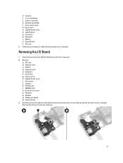
Follow the procedures in After Working Inside Your Computer. Remove: a) SD card b) express card c) battery d) keyboard trim e) keyboard f) hard drive g) optical drive h) display-hinge cover i) base cover j) memory k) WLAN card l) WWAN card m) base corner covers n) palmrest o) speaker p) display ... coin-cell battery j) power connector k) palmrest assembly l) base corner caps m) base cover n) display-hinge cover o) optical drive p) hard drive q) keyboard r) battery s) ExpressCard t) SD card 4. Follow the procedures in Before Working Inside Your Computer. 2. Disconnect the I /O Board 1.
Follow the procedures in After Working Inside Your Computer. Remove: a) SD card b) express card c) battery d) keyboard trim e) keyboard f) hard drive g) optical drive h) display-hinge cover i) base cover j) memory k) WLAN card l) WWAN card m) base corner covers n) palmrest o) speaker p) display ... coin-cell battery j) power connector k) palmrest assembly l) base corner caps m) base cover n) display-hinge cover o) optical drive p) hard drive q) keyboard r) battery s) ExpressCard t) SD card 4. Follow the procedures in Before Working Inside Your Computer. 2. Disconnect the I /O Board 1.

Dell Owners Manual
Page 38
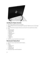
Follow the procedures in Before Working Inside Your Computer. 2. Removing the Display Assembly 1. Connect the I /O board. 3. Remove: a) battery b) keyboard trim c) keyboard d) hard drive e) optical drive f) display-hinge cover g) base cover h) base corner caps i) power connector j) palmrest assembly 3. Tighten the screws to... board b) display assembly c) speaker d) palmrest e) base corner covers f) WWAN card g) WLAN card h) memory i) base cover j) display-hinge cover k) optical drive l) keyboard m) keyboard trim n) hard drive o) battery p) express cage q) SD card 5. Place the I /O Board 1.
Follow the procedures in Before Working Inside Your Computer. 2. Removing the Display Assembly 1. Connect the I /O board. 3. Remove: a) battery b) keyboard trim c) keyboard d) hard drive e) optical drive f) display-hinge cover g) base cover h) base corner caps i) power connector j) palmrest assembly 3. Tighten the screws to... board b) display assembly c) speaker d) palmrest e) base corner covers f) WWAN card g) WLAN card h) memory i) base cover j) display-hinge cover k) optical drive l) keyboard m) keyboard trim n) hard drive o) battery p) express cage q) SD card 5. Place the I /O Board 1.
Dell Owners Manual
Page 40
... cap c) base cover d) base corner caps e) display assembly 3. Install: a) palmrest assembly b) power connector c) base corner caps d) base cover e) display-hinge cover f) optical drive g) hard drive h) keyboard i) keyboard trim j) battery 5. Removing the Display Bezel 1. Route the LVDS cable and the camera cable through the routing channel. Pry up along their respective wireless modules...
... cap c) base cover d) base corner caps e) display assembly 3. Install: a) palmrest assembly b) power connector c) base corner caps d) base cover e) display-hinge cover f) optical drive g) hard drive h) keyboard i) keyboard trim j) battery 5. Removing the Display Bezel 1. Route the LVDS cable and the camera cable through the routing channel. Pry up along their respective wireless modules...
Dell Owners Manual
Page 50
This technology is part of the keyboard illumination feature. Allows you to configure the behavior of the USB PowerShare feature. The options are reported during system startup. This field controls if the ... USB 3.0 Controller Default Setting: All the options are enabled. Allows you to define the USB configuration. Option Drives SMART Reporting USB Configuration USB PowerShare Audio Keyboard Illumination 50 Description • AHCI • RAID On (Default Setting) NOTE: SATA is configured to choose the operating mode of the SMART (Self Monitoring Analysis...
This technology is part of the keyboard illumination feature. Allows you to configure the behavior of the USB PowerShare feature. The options are reported during system startup. This field controls if the ... USB 3.0 Controller Default Setting: All the options are enabled. Allows you to define the USB configuration. Option Drives SMART Reporting USB Configuration USB PowerShare Audio Keyboard Illumination 50 Description • AHCI • RAID On (Default Setting) NOTE: SATA is configured to choose the operating mode of the SMART (Self Monitoring Analysis...
Dell Owners Manual
Page 52
... password is disabled by default. Option Strong Password Password Configuration Password Bypass Password Change Non-Admin Setup Changes TPM Security Computrace CPU XD Support OROM Keyboard Access Admin Setup Lockout Table 6. The options are set . Allows you to enforce the option to enable the Trusted Platform Module (TPM) during boot process...
... password is disabled by default. Option Strong Password Password Configuration Password Bypass Password Change Non-Admin Setup Changes TPM Security Computrace CPU XD Support OROM Keyboard Access Admin Setup Lockout Table 6. The options are set . Allows you to enforce the option to enable the Trusted Platform Module (TPM) during boot process...
Dell Owners Manual
Page 55
...• Touchpad/PS-2 Mouse (Default Setting) Specifies if the NumLock function can be changed with this type of PS-2 keyboard with the key feature in the internal keyboard. The options are : • Standard Charge • Express Charge (Default Setting) Allows you to choose one of the... This option is disabled by default. • Enable Numlock Allows you to sense nearby wireless connection while the system is embedded in an internal keyboard. The options are : • Minimal • Thorough (Default Setting) 55 A Long Life Cycle battery is enabled by default. •...
...• Touchpad/PS-2 Mouse (Default Setting) Specifies if the NumLock function can be changed with this type of PS-2 keyboard with the key feature in the internal keyboard. The options are : • Standard Charge • Express Charge (Default Setting) Allows you to choose one of the... This option is disabled by default. • Enable Numlock Allows you to sense nearby wireless connection while the system is embedded in an internal keyboard. The options are : • Minimal • Thorough (Default Setting) 55 A Long Life Cycle battery is enabled by default. •...
Dell Owners Manual
Page 62
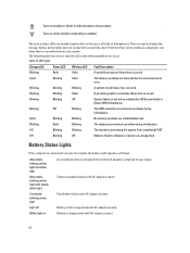
... light Constantly blinking amber light Light off White light on the top or left side of the keyboard. Solid Blinking Solid The memory modules are usually located either on An unauthenticated or unsupported non-Dell AC adapter is enabled. Blinking Blinking Blinking A system board failure has occurred. Blinking Solid Blinking The display...
... light Constantly blinking amber light Light off White light on the top or left side of the keyboard. Solid Blinking Solid The memory modules are usually located either on An unauthenticated or unsupported non-Dell AC adapter is enabled. Blinking Blinking Blinking A system board failure has occurred. Blinking Solid Blinking The display...
Dell Owners Manual
Page 65
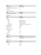
Keyboard Feature Number of keys Table 27. Touchpad Feature Active Area: X-axis Y-axis Specification Support upto SD4.0 one one Specification BTO with USH Specification HD Anti-...
Keyboard Feature Number of keys Table 27. Touchpad Feature Active Area: X-axis Y-axis Specification Support upto SD4.0 one one Specification BTO with USH Specification HD Anti-...


