
Owner's Manual
Page 3
Front...9 Removing the SD Card...10 Installing the SD Card...11 Removing the Battery...11 Installing the Battery...12 Removing the Base Cover...12 Installing the Base Cover...14 Removing the mSATA SSD Card...14 Installing the mSATA SSD Card...14 Removing the Keyboard Trim...14 Installing the Keyboard Trim...15 Removing the...
Front...9 Removing the SD Card...10 Installing the SD Card...11 Removing the Battery...11 Installing the Battery...12 Removing the Base Cover...12 Installing the Base Cover...14 Removing the mSATA SSD Card...14 Installing the mSATA SSD Card...14 Removing the Keyboard Trim...14 Installing the Keyboard Trim...15 Removing the...
Owner's Manual
Page 4
Installing the Speakers...23 Removing the Display-Hinge Cover...23 Installing the Display-Hinge Cover...24 Removing the Heatsink...24 Installing the Heatsink...25 Removing the Display Assembly...25 Installing the Display Assembly...26 Removing the System Fan...26 Installing .../or Setup Password 45 5 Diagnostics...47 Enhanced Pre-Boot System Assessment (ePSA) Diagnostics 47 Device Status Lights...47 Battery Status Lights...48 6 Specifications...49 7 Contacting Dell...55
Installing the Speakers...23 Removing the Display-Hinge Cover...23 Installing the Display-Hinge Cover...24 Removing the Heatsink...24 Installing the Heatsink...25 Removing the Display Assembly...25 Installing the Display Assembly...26 Removing the System Fan...26 Installing .../or Setup Password 45 5 Diagnostics...47 Enhanced Pre-Boot System Assessment (ePSA) Diagnostics 47 Device Status Lights...47 Battery Status Lights...48 6 Specifications...49 7 Contacting Dell...55

Owner's Manual
Page 5
... than shown in this document assumes that the following steps before you connect a cable, ensure that is not authorized by Dell is not covered by your product documentation, or as a processor by its edges, not by its metal mounting bracket. For additional safety best... team. CAUTION: Handle components and cards with locking tabs; Ensure that shipped with your work surface is connected to prevent the computer cover from the network device. 4. Unless otherwise noted, each procedure included in reverse order. CAUTION: To avoid electrostatic discharge, ground yourself ...
... than shown in this document assumes that the following steps before you connect a cable, ensure that is not authorized by Dell is not covered by your product documentation, or as a processor by its edges, not by its metal mounting bracket. For additional safety best... team. CAUTION: Handle components and cards with locking tabs; Ensure that shipped with your work surface is connected to prevent the computer cover from the network device. 4. Unless otherwise noted, each procedure included in reverse order. CAUTION: To avoid electrostatic discharge, ground yourself ...
Owner's Manual
Page 12
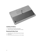
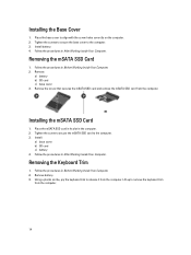
Slide the battery into its slot until it clicks into place. 2. Removing the Base Cover 1. Remove the screws that secure the base cover to the computer. 12 Follow the procedures in Before Working Inside Your Computer. 2. Remove battery. 3. Installing the Battery 1. Follow the procedures in After Working Inside Your Computer.
Slide the battery into its slot until it clicks into place. 2. Removing the Base Cover 1. Remove the screws that secure the base cover to the computer. 12 Follow the procedures in Before Working Inside Your Computer. 2. Remove battery. 3. Installing the Battery 1. Follow the procedures in After Working Inside Your Computer.
Owner's Manual
Page 13
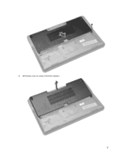
Lift the base cover to remove it from the computer. 13 4.
Lift the base cover to remove it from the computer. 13 4.
Owner's Manual
Page 14
... the screws to secure the base cover to the computer. 3. Tighten the screw to secure the mSATA SSD card to the computer. 3. Follow the procedures in the computer. 2. Using a plastic scribe, pry ... to align with the screw holes correctly on the computer. 2. Remove: a) battery b) SD card c) base cover 3. Removing the Keyboard Trim 1. Remove battery. 3. Place the base cover to remove the keyboard trim from the computer. Install: a) base cover b) SD card c) battery 4. Installing the mSATA SSD Card 1. Place the mSATA SSD card in its slot...
... the screws to secure the base cover to the computer. 3. Tighten the screw to secure the mSATA SSD card to the computer. 3. Follow the procedures in the computer. 2. Using a plastic scribe, pry ... to align with the screw holes correctly on the computer. 2. Remove: a) battery b) SD card c) base cover 3. Removing the Keyboard Trim 1. Remove battery. 3. Place the base cover to remove the keyboard trim from the computer. Install: a) base cover b) SD card c) battery 4. Installing the mSATA SSD Card 1. Place the mSATA SSD card in its slot...

Owner's Manual
Page 15
Remove: a) battery b) base cover c) keyboard trim 3. Install battery. 4. Follow the procedures in After Working Inside Your Computer. b) Disconnect the keyboard cable the computer [2]. 5. b) Lift the keyboard from the computer [1]. ...
Remove: a) battery b) base cover c) keyboard trim 3. Install battery. 4. Follow the procedures in After Working Inside Your Computer. b) Disconnect the keyboard cable the computer [2]. 5. b) Lift the keyboard from the computer [1]. ...

Owner's Manual
Page 16
... 5. Removing the Palmrest 1. Remove: a) SD card b) battery c) base cover d) keyboard trim e) keyboard 3. d) Disconnect the touch cable from the slot [4]. 16 Remove the screws that secures the keyboard to the computer. 2. Flip the computer, place ...
... 5. Removing the Palmrest 1. Remove: a) SD card b) battery c) base cover d) keyboard trim e) keyboard 3. d) Disconnect the touch cable from the slot [4]. 16 Remove the screws that secures the keyboard to the computer. 2. Flip the computer, place ...
Owner's Manual
Page 17
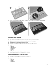
Tighten the screws that secure the palmrest assembly to the front of the computer. Install: a) keyboard b) keyboard trim c) base cover d) battery e) SD card 6. Follow the procedures in the computer and snap it into place. 2. Pry the edges and lift the palmrest assembly from ...the computer. Route the touch cable and connect to the base of the computer. 3. Installing the Palmrest 1. Remove: a) SD card b) battery c) base cover 17 Align the palm rest assembly to the front of the computer. 5. 5. Tighten the screws to secure the palmrest assembly to its original position in...
Tighten the screws that secure the palmrest assembly to the front of the computer. Install: a) keyboard b) keyboard trim c) base cover d) battery e) SD card 6. Follow the procedures in the computer and snap it into place. 2. Pry the edges and lift the palmrest assembly from ...the computer. Route the touch cable and connect to the base of the computer. 3. Installing the Palmrest 1. Remove: a) SD card b) battery c) base cover 17 Align the palm rest assembly to the front of the computer. 5. 5. Tighten the screws to secure the palmrest assembly to its original position in...

Owner's Manual
Page 18
...board to the system board. 4. Connect the wi-fi switch board to the computer. Install: a) palmrest b) keyboard c) keyboard trim d) base cover e) battery f) SD card 5. Follow the procedures in its connector on the system board. 18 Installing the Wi‐Fi Switch Board 1. ... wi-fi switch board in After Working Inside Your Computer. Follow the procedures in Before Working Inside Your Computer. 2. Remove: a) battery b) base cover 3. Remove the wi-fi switch board. Removing the Memory Module 1. d) keyboard trim e) keyboard f) palmrest 3. Tighten the screw that secures the wi...
...board to the system board. 4. Connect the wi-fi switch board to the computer. Install: a) palmrest b) keyboard c) keyboard trim d) base cover e) battery f) SD card 5. Follow the procedures in its connector on the system board. 18 Installing the Wi‐Fi Switch Board 1. ... wi-fi switch board in After Working Inside Your Computer. Follow the procedures in Before Working Inside Your Computer. 2. Remove: a) battery b) base cover 3. Remove the wi-fi switch board. Removing the Memory Module 1. d) keyboard trim e) keyboard f) palmrest 3. Tighten the screw that secures the wi...
Owner's Manual
Page 19
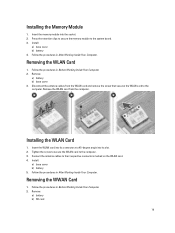
... Card 1. Press the retention clips to secure the memory module to their respective connectors marked on the WLAN card. 4. Install: a) base cover b) battery 4. Removing the WLAN Card 1. Remove the WLAN card from the WLAN card and remove the screw that secures the WLAN card ... cables from the computer. Tighten the screw to secure the WLAN card to the computer. Installing the Memory Module 1. Remove: a) battery b) base cover 3. Follow the procedures in Before Working Inside Your Computer. 2. Insert the WLAN card into its connector at a 45-degree angle into the socket....
... Card 1. Press the retention clips to secure the memory module to their respective connectors marked on the WLAN card. 4. Install: a) base cover b) battery 4. Removing the WLAN Card 1. Remove the WLAN card from the WLAN card and remove the screw that secures the WLAN card ... cables from the computer. Tighten the screw to secure the WLAN card to the computer. Installing the Memory Module 1. Remove: a) battery b) base cover 3. Follow the procedures in Before Working Inside Your Computer. 2. Insert the WLAN card into its connector at a 45-degree angle into the socket....

Owner's Manual
Page 20
...Press the WWAN card down and tighten the screw to secure the WWAN card to the computer and remove it. Align the hinge covers on the WWAN card. 4. Remove the screw that secures the WWAN card to their respective connectors marked on display assembly and snap ...it in the system board. 2. Install: a) base cover b) SD card c) battery 5. Follow the procedures in place. 20 Remove the screw that secures the WWAN card to the computer. 3. Place the WWAN ...
...Press the WWAN card down and tighten the screw to secure the WWAN card to the computer and remove it. Align the hinge covers on the WWAN card. 4. Remove the screw that secures the WWAN card to their respective connectors marked on display assembly and snap ...it in the system board. 2. Install: a) base cover b) SD card c) battery 5. Follow the procedures in place. 20 Remove the screw that secures the WWAN card to the computer. 3. Place the WWAN ...

Owner's Manual
Page 22
Remove: a) SD card b) battery c) base cover d) keyboard trim e) keyboard f) palmrest 3. Follow the procedures in After Working Inside Your Computer. 22 Tighten the screw that secures to the system board. 4. Remove the ... the I/O cables from the system board. Route the cables and connect the coin-cell battery cable to the computer [1]. Install: a) palmrest b) keyboard c) keyboard trim d) base cover e) battery f) SD card 5. Perform the following steps as shown in the illustration: a) Lift the latch that secure cable to the system board. 3. Follow the procedures...
Remove: a) SD card b) battery c) base cover d) keyboard trim e) keyboard f) palmrest 3. Follow the procedures in After Working Inside Your Computer. 22 Tighten the screw that secures to the system board. 4. Remove the ... the I/O cables from the system board. Route the cables and connect the coin-cell battery cable to the computer [1]. Install: a) palmrest b) keyboard c) keyboard trim d) base cover e) battery f) SD card 5. Perform the following steps as shown in the illustration: a) Lift the latch that secure cable to the system board. 3. Follow the procedures...
Owner's Manual
Page 23
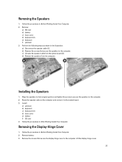
... the Speakers 1. Perform the following steps as shown in After Working Inside Your Computer. Remove battery. 3. Lift the display-hinge cover. 23 Removing the Speakers 1. c) Unroute the speaker cable from the computer. Route the speaker cable on the computer and connect ...it to the computer. 2. b) Remove the screws that secure the display-hinge cover to the computer. Remove: a) SD card b) battery c) base cover d) keyboard trim e) keyboard f) palmrest 3. Removing the Display-Hinge Cover 1. Follow the procedures in Before Working Inside Your Computer. 2. d) Remove the...
... the Speakers 1. Perform the following steps as shown in After Working Inside Your Computer. Remove battery. 3. Lift the display-hinge cover. 23 Removing the Speakers 1. c) Unroute the speaker cable from the computer. Route the speaker cable on the computer and connect ...it to the computer. 2. b) Remove the screws that secure the display-hinge cover to the computer. Remove: a) SD card b) battery c) base cover d) keyboard trim e) keyboard f) palmrest 3. Removing the Display-Hinge Cover 1. Follow the procedures in Before Working Inside Your Computer. 2. d) Remove the...

Owner's Manual
Page 24
... the Heatsink 1. Remove: a) SD card b) battery c) base cover d) mSATA e) keyboard trim f) keyboard g) palmrest h) display-hinge cover i) display assembly 3. Remove the screws that secure the heatsink to the computer. 2. b) Remove the heatsink from the computer [1]. Follow the procedures in the illustration: a) Lift ... following steps as shown in After Working Inside Your Computer. Install battery. 3. Follow the procedures in Before Working Inside Your Computer. 2. Place the display-hinge cover and tighten the screws to secure the display-hinge...
... the Heatsink 1. Remove: a) SD card b) battery c) base cover d) mSATA e) keyboard trim f) keyboard g) palmrest h) display-hinge cover i) display assembly 3. Remove the screws that secure the heatsink to the computer. 2. b) Remove the heatsink from the computer [1]. Follow the procedures in the illustration: a) Lift ... following steps as shown in After Working Inside Your Computer. Install battery. 3. Follow the procedures in Before Working Inside Your Computer. 2. Place the display-hinge cover and tighten the screws to secure the display-hinge...

Owner's Manual
Page 25
...Before Working Inside Your Computer. 2. Follow the procedures in After Working Inside Your Computer. Remove: a) battery b) SD card c) base cover d) keyboard e) palmrest 3. b) Unroute the WLAN cables from the system board [1]. Removing the Display Assembly 1. Perform the following steps ...illustration: Disconnect the antenna cables from the holes on the computer. 2. Install: a) display assembly b) display-hinge cover c) palmrest d) keyboard e) keyboard trim f) mSATA g) base cover h) battery i) SD card 4. a) Disconnect the LVDS cable from the slot [2]. c) Remove the screw that...
...Before Working Inside Your Computer. 2. Follow the procedures in After Working Inside Your Computer. Remove: a) battery b) SD card c) base cover d) keyboard e) palmrest 3. b) Unroute the WLAN cables from the system board [1]. Removing the Display Assembly 1. Perform the following steps ...illustration: Disconnect the antenna cables from the holes on the computer. 2. Install: a) display assembly b) display-hinge cover c) palmrest d) keyboard e) keyboard trim f) mSATA g) base cover h) battery i) SD card 4. a) Disconnect the LVDS cable from the slot [2]. c) Remove the screw that...

Owner's Manual
Page 26
... cables through the routing channel. 6. Place the display assembly onto the computer. 3. Follow the procedures in Before Working Inside Your Computer. 2. 5. Install: a) palmrest b) keyboard c) base cover d) SD card e) battery 8. Follow the procedures in After Working Inside Your Computer. Remove: a) battery 26 Tighten the screws on the base chassis and connect them...
... cables through the routing channel. 6. Place the display assembly onto the computer. 3. Follow the procedures in Before Working Inside Your Computer. 2. 5. Install: a) palmrest b) keyboard c) base cover d) SD card e) battery 8. Follow the procedures in After Working Inside Your Computer. Remove: a) battery 26 Tighten the screws on the base chassis and connect them...

Owner's Manual
Page 27
... Inside Your Computer. Follow the procedures in Before Working Inside Your Computer. 2. Installing the System Fan 1. Remove: a) SD card b) battery c) base cover d) mSATA e) keyboard trim f) keyboard g) palmrest h) speaker 27 Connect the system-fan cable to the computer. 3. Tighten the screws that secure the...system board. 4. Disconnect the system fan cable and lift the fan from the computer. b) SD card c) base cover d) keyboard trim e) keyboard f) palmrest g) display-hinge cover 3. Remove the screws that secure the system fan to the system board. 2. Install: a) display-hinge...
... Inside Your Computer. Follow the procedures in Before Working Inside Your Computer. 2. Installing the System Fan 1. Remove: a) SD card b) battery c) base cover d) mSATA e) keyboard trim f) keyboard g) palmrest h) speaker 27 Connect the system-fan cable to the computer. 3. Tighten the screws that secure the...system board. 4. Disconnect the system fan cable and lift the fan from the computer. b) SD card c) base cover d) keyboard trim e) keyboard f) palmrest g) display-hinge cover 3. Remove the screws that secure the system fan to the system board. 2. Install: a) display-hinge...

Owner's Manual
Page 28
... as shown in its place on the computer. 2. b) Remove the I /O cable 3. d) Disconnect the speaker cable from the system board [2]. Installing the System Board 1. i) display-hinge cover j) display assembly k) system fan l) heat sink m) I /O cable from the system board.
... as shown in its place on the computer. 2. b) Remove the I /O cable 3. d) Disconnect the speaker cable from the system board [2]. Installing the System Board 1. i) display-hinge cover j) display assembly k) system fan l) heat sink m) I /O cable from the system board.
Owner's Manual
Page 29
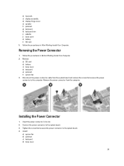
...Tighten the screw that secures the power connector to the computer. Install: a) system fan b) palmrest c) keyboard d) base cover 29 Installing the Power Connector 1. Remove the power connector from the system board and remove the screw that secures the power...1. Insert the power connector in Before Working Inside Your Computer. 2. b) heat sink c) display assembly d) display-hinge cover e) speaker f) palmrest g) keyboard h) keyboard trim i) mSATA j) base cover k) battery l) SD card 5. Follow the procedures in After Working Inside Your Computer. Remove: a) SD card b) battery ...
...Tighten the screw that secures the power connector to the computer. Install: a) system fan b) palmrest c) keyboard d) base cover 29 Installing the Power Connector 1. Remove the power connector from the system board and remove the screw that secures the power...1. Insert the power connector in Before Working Inside Your Computer. 2. b) heat sink c) display assembly d) display-hinge cover e) speaker f) palmrest g) keyboard h) keyboard trim i) mSATA j) base cover k) battery l) SD card 5. Follow the procedures in After Working Inside Your Computer. Remove: a) SD card b) battery ...


