
User Manual
Page 1
... status lights 21. Front View 1. camera LED (optional) 5. USB 3.0 connector 10. hard drive 12. touchpad buttons (3) 16. track stick 19. display latches (2) 2. display latch release button 15. DisplayPort connector 9. touchpad 17. keyboard 20. track-stick buttons (3) 18. Dell Precision Mobile Workstation M4700/M6700 Setup And Features Information About Warnings WARNING: A WARNING indicates a potential for...
... status lights 21. Front View 1. camera LED (optional) 5. USB 3.0 connector 10. hard drive 12. touchpad buttons (3) 16. track stick 19. display latches (2) 2. display latch release button 15. DisplayPort connector 9. touchpad 17. keyboard 20. track-stick buttons (3) 18. Dell Precision Mobile Workstation M4700/M6700 Setup And Features Information About Warnings WARNING: A WARNING indicates a potential for...

User Manual
Page 2
VGA connector 3. power connector 7. Base View 1. cooling vents (2) 2. Base View 11. power light 15. 10-in-1 card reader slot 16. battery bay 2 microphone connector M4700 - smart card reader slot 19. eSATA/USB 2.0 connector 5. USB 2.0 connectors (2) 9. battery status light 14. ExpressCard slot Figure 3. security cable slot 8. hard-drive status light 13. Back View 1. Figure 2. network connector 4. HDMI connector 6. IEEE 1394 port (4-pin) 10. headphone connector 12. optical-drive eject button 17. optical drive 18.
VGA connector 3. power connector 7. Base View 1. cooling vents (2) 2. Base View 11. power light 15. 10-in-1 card reader slot 16. battery bay 2 microphone connector M4700 - smart card reader slot 19. eSATA/USB 2.0 connector 5. USB 2.0 connectors (2) 9. battery status light 14. ExpressCard slot Figure 3. security cable slot 8. hard-drive status light 13. Back View 1. Figure 2. network connector 4. HDMI connector 6. IEEE 1394 port (4-pin) 10. headphone connector 12. optical-drive eject button 17. optical drive 18.

User Manual
Page 3
.... device status lights 21. SIM slot 4. display latches (2) 2. speakers (2) 7. fingerprint reader (optional) 13. touchpad 17. 2. USB 3.0 PowerShare connector 11. volume control buttons (3) 3 camera LED (optional) 5. hard drive 12. touchpad buttons (3) 16. DisplayPort connector 9. power button 8. track stick 19. microphones (2) (optional) 3. display-latch release button 15. HDD eject latch 3. dock I/O port M6700 - USB...
.... device status lights 21. SIM slot 4. display latches (2) 2. speakers (2) 7. fingerprint reader (optional) 13. touchpad 17. 2. USB 3.0 PowerShare connector 11. volume control buttons (3) 3 camera LED (optional) 5. hard drive 12. touchpad buttons (3) 16. DisplayPort connector 9. power button 8. track stick 19. microphones (2) (optional) 3. display-latch release button 15. HDD eject latch 3. dock I/O port M6700 - USB...

User Manual
Page 4
VGA connector 4. Base View 11. cooling vents (2) 2. HDMI connector 5. headphone connector 12. power light 15. 10-in-1 card reader slot 16. Base View 1. network connector 3. microphone connector M6700 - eSATA/USB 2.0 connector 6. security cable slot 8. optical-drive eject button 17. USB 2.0 connectors (2) 9. IEEE 1394 port (6-pin, powered) 10. hard-drive status light 13. optical drive 18. smart card reader slot 19. Figure 5. battery status light 14. battery bay 4 power connector 7. ExpressCard slot Figure 6. Back View 1.
VGA connector 4. Base View 11. cooling vents (2) 2. HDMI connector 5. headphone connector 12. power light 15. 10-in-1 card reader slot 16. Base View 1. network connector 3. microphone connector M6700 - eSATA/USB 2.0 connector 6. security cable slot 8. optical-drive eject button 17. USB 2.0 connectors (2) 9. IEEE 1394 port (6-pin, powered) 10. hard-drive status light 13. optical drive 18. smart card reader slot 19. Figure 5. battery status light 14. battery bay 4 power connector 7. ExpressCard slot Figure 6. Back View 1.

User Manual
Page 5
...connector on the AC adapter to the electrical outlet. AC Adapter 2. Connect the network cable (optional). Connect USB devices, such as a 1394 hard drive (optional). 5 Figure 8. SIM slot 4. battery release latch 5. dock I/O port Quick Setup WARNING: Before you follow the angle of the ...computer and to avoid damaging the cable. CAUTION: When you did not order them. 1. For additional best practices information, see www.dell.com/regulatory_compliance WARNING: The AC adapter works with your computer. Network Connector 3. HDD eject latch 3. Figure 9. When you wrap the ...
...connector on the AC adapter to the electrical outlet. AC Adapter 2. Connect the network cable (optional). Connect USB devices, such as a 1394 hard drive (optional). 5 Figure 8. SIM slot 4. battery release latch 5. dock I/O port Quick Setup WARNING: Before you follow the angle of the ...computer and to avoid damaging the cable. CAUTION: When you did not order them. 1. For additional best practices information, see www.dell.com/regulatory_compliance WARNING: The AC adapter works with your computer. Network Connector 3. HDD eject latch 3. Figure 9. When you wrap the ...

Owner's Manual
Page 3
... Memory...19 Installing the Primary Memory...19 Removing the Secondary Memory...20 Installing the Secondary Memory...20 Removing the Optical Drive...20 Installing the Optical Drive...22 Removing the Hard Drive...22 Installing the Hard Drive...23 Removing the Wireless Local Area Network (WLAN) Card 23 Installing the Wireless Local Area Network (WLAN) Card 24 Removing...
... Memory...19 Installing the Primary Memory...19 Removing the Secondary Memory...20 Installing the Secondary Memory...20 Removing the Optical Drive...20 Installing the Optical Drive...22 Removing the Hard Drive...22 Installing the Hard Drive...23 Removing the Wireless Local Area Network (WLAN) Card 23 Installing the Wireless Local Area Network (WLAN) Card 24 Removing...
Owner's Manual
Page 22
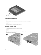
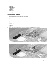
... Inside Your Computer. 2. Slide the hard drive latch to the computer. 3. Slide the optical drive into its slot and tighten the screw to secure the optical drive to the unlock position and pull out the hard drive from the computer. 22 Removing the Hard Drive 1. Remove the screws that secure the hard drive to the optical drive. 2. Tighten the screw to...
... Inside Your Computer. 2. Slide the hard drive latch to the computer. 3. Slide the optical drive into its slot and tighten the screw to secure the optical drive to the unlock position and pull out the hard drive from the computer. 22 Removing the Hard Drive 1. Remove the screws that secure the hard drive to the optical drive. 2. Tighten the screw to...
Owner's Manual
Page 23
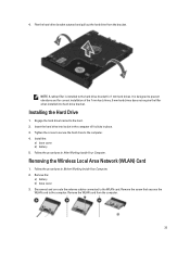
... installed into its slot in the computer till it clicks in place. 3. Engage the hard drive bracket to the computer. 4. Installing the Hard Drive 1. Tighten the screw to secure the hard drive to the hard . 2. Flex the hard-drive bracket outward and pull out the hard drive from the computer. 23 Follow the procedures in Before Working Inside Your Computer. 2. It...
... installed into its slot in the computer till it clicks in place. 3. Engage the hard drive bracket to the computer. 4. Installing the Hard Drive 1. Tighten the screw to secure the hard drive to the hard . 2. Flex the hard-drive bracket outward and pull out the hard drive from the computer. 23 Follow the procedures in Before Working Inside Your Computer. 2. It...

Owner's Manual
Page 28
Replace the coin-cell battery in its slot in After Working Inside Your Computer. Follow the procedures in the computer. 2. Removing the Palmrest 1. Remove the: a) battery b) base cover c) keyboard trim d) keyboard e) optical drive f) hard drive drive 3. Install the: a) base cover b) battery 4. Installing the Coin-Cell Battery 1. Follow the procedures in Before Working Inside Your Computer. 2. Connect the coin-cell battery cable. 3. Disconnect the RFID and fingerprint reader cables 28
Replace the coin-cell battery in its slot in After Working Inside Your Computer. Follow the procedures in the computer. 2. Removing the Palmrest 1. Remove the: a) battery b) base cover c) keyboard trim d) keyboard e) optical drive f) hard drive drive 3. Install the: a) base cover b) battery 4. Installing the Coin-Cell Battery 1. Follow the procedures in Before Working Inside Your Computer. 2. Connect the coin-cell battery cable. 3. Disconnect the RFID and fingerprint reader cables 28

Owner's Manual
Page 31
... until it snaps in place. 2. Follow the procedures in After Working Inside Your Computer. Align the palmrest to the base of the computer. 4. Install the: a) hard drive b) optical drive c) keyboard d) keyboard trim e) base cover f) battery 6. Removing the ExpressCard Module 1. Follow the procedures in Before Working Inside Your Computer. 2. Tighten the screws to secure...
... until it snaps in place. 2. Follow the procedures in After Working Inside Your Computer. Align the palmrest to the base of the computer. 4. Install the: a) hard drive b) optical drive c) keyboard d) keyboard trim e) base cover f) battery 6. Removing the ExpressCard Module 1. Follow the procedures in Before Working Inside Your Computer. 2. Tighten the screws to secure...
Owner's Manual
Page 32
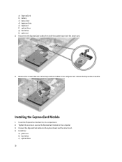
Remove the screws that secure the ExpressCard module to the computer 3. a) ExpressCard b) battery c) base cover d) keyboard trim e) keyboard f) optical drive g) hard drive h) palm rest 3. Disconnect the ExpressCard cables from both the system board and the smart card. 4. Insert the ExpressCard module into its compartment. 2. Installing the ExpressCard ... module to the computer and remove the ExpressCard module. Connect the ExpressCard cables to the system board and the smart card. 4. Install the: a) palm rest b) hard drive c) optical drive 32
Remove the screws that secure the ExpressCard module to the computer 3. a) ExpressCard b) battery c) base cover d) keyboard trim e) keyboard f) optical drive g) hard drive h) palm rest 3. Disconnect the ExpressCard cables from both the system board and the smart card. 4. Insert the ExpressCard module into its compartment. 2. Installing the ExpressCard ... module to the computer and remove the ExpressCard module. Connect the ExpressCard cables to the system board and the smart card. 4. Install the: a) palm rest b) hard drive c) optical drive 32
Owner's Manual
Page 33
Disconnect the camera cable and loosen the captive screws that secure the heat sink to the computer. 4. Remove the: a) battery b) base cover c) keyboard trim d) keyboard e) optical drive f) hard drive g) palm rest h) processor fan 3. Follow the procedures in After Working Inside Your Computer. Follow the procedures in Before Working Inside Your Computer. 2. Removing the Heat Sink 1. d) keyboard e) keyboard trim f) base cover g) battery h) ExpressCard 5. Remove the heat sink from the computer. 33
Disconnect the camera cable and loosen the captive screws that secure the heat sink to the computer. 4. Remove the: a) battery b) base cover c) keyboard trim d) keyboard e) optical drive f) hard drive g) palm rest h) processor fan 3. Follow the procedures in After Working Inside Your Computer. Follow the procedures in Before Working Inside Your Computer. 2. Removing the Heat Sink 1. d) keyboard e) keyboard trim f) base cover g) battery h) ExpressCard 5. Remove the heat sink from the computer. 33

Owner's Manual
Page 34
...Inside Your Computer. Tighten the captive screws to secure the heat sink to the system board. 4. Install the: a) processor fan b) palm rest c) hard drive d) optical drive e) keyboard f) keyboard trim g) base cover h) battery 5. Follow the procedures in its slot. 2. Remove the processor from the computer. Align the notches.... 2. Rotate the processor cam lock in a counter-clockwise direction. Remove the: a) battery b) base cover c) keyboard trim d) keyboard e) optical drive f) hard drive g) palm rest h) processor fan i) heat sink 3. Install the: a) heat sink b) processor fan c) palm rest...
...Inside Your Computer. Tighten the captive screws to secure the heat sink to the system board. 4. Install the: a) processor fan b) palm rest c) hard drive d) optical drive e) keyboard f) keyboard trim g) base cover h) battery 5. Follow the procedures in its slot. 2. Remove the processor from the computer. Align the notches.... 2. Rotate the processor cam lock in a counter-clockwise direction. Remove the: a) battery b) base cover c) keyboard trim d) keyboard e) optical drive f) hard drive g) palm rest h) processor fan i) heat sink 3. Install the: a) heat sink b) processor fan c) palm rest...

Owner's Manual
Page 35
e) optical drive f) keyboard g) keyboard trim h) base cover i) battery 4. Removing the Video-Card Heat Sink 1. Remove the: a) battery b) bottom door c) keyboard trim d) keyboard e) optical drive f) hard drive g) palm rest h) video fan 3. Follow the procedures in After Working Inside Your Computer. Remove the antenna cables from the routing channels. 35 Disconnect and un-route any antenna cables connected to installed wireless cards. 4. Follow the procedures in Before Working Inside Your Computer. 2.
e) optical drive f) keyboard g) keyboard trim h) base cover i) battery 4. Removing the Video-Card Heat Sink 1. Remove the: a) battery b) bottom door c) keyboard trim d) keyboard e) optical drive f) hard drive g) palm rest h) video fan 3. Follow the procedures in After Working Inside Your Computer. Remove the antenna cables from the routing channels. 35 Disconnect and un-route any antenna cables connected to installed wireless cards. 4. Follow the procedures in Before Working Inside Your Computer. 2.

Owner's Manual
Page 37
Install the: a) video fan b) palm rest c) hard drive d) optical drive e) keyboard f) keyboard trim g) bottom door h) battery 5. Tighten the captive screws to the installed wireless cards. 4. Follow the procedures in Before Working Inside Your Computer.... the computer. 37 Route and connect the antenna cables to secure the heat sink. 3. Remove the: a) battery b) base cover c) keyboard trim d) keyboard e) optical drive f) hard drive g) palm rest h) video-card fan i) video-card heat sink j) heatsink 3. Slide the heat sink into its original position in the computer. 2. Remove the screws ...
Install the: a) video fan b) palm rest c) hard drive d) optical drive e) keyboard f) keyboard trim g) bottom door h) battery 5. Tighten the captive screws to the installed wireless cards. 4. Follow the procedures in Before Working Inside Your Computer.... the computer. 37 Route and connect the antenna cables to secure the heat sink. 3. Remove the: a) battery b) base cover c) keyboard trim d) keyboard e) optical drive f) hard drive g) palm rest h) video-card fan i) video-card heat sink j) heatsink 3. Slide the heat sink into its original position in the computer. 2. Remove the screws ...

Owner's Manual
Page 38
... in After Working Inside Your Computer. Follow the procedures in the computer. 2. Install the: a) heatsink b) video-card heat sink c) video-card fan d) palm rest e) hard drive f) optical drive g) keyboard h) keyboard trim i) base cover j) battery 4. Tighten the screws to secure it to the computer. 3. Follow the procedures in Before Working Inside Your Computer. 2. Disconnect...
... in After Working Inside Your Computer. Follow the procedures in the computer. 2. Install the: a) heatsink b) video-card heat sink c) video-card fan d) palm rest e) hard drive f) optical drive g) keyboard h) keyboard trim i) base cover j) battery 4. Tighten the screws to secure it to the computer. 3. Follow the procedures in Before Working Inside Your Computer. 2. Disconnect...
Owner's Manual
Page 40
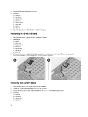
...4. Tighten the screws to secure the switch board to its original position on the computer. 2. Install the: a) palmrest b) hard drive c) optical drive d) keyboard 40 Follow the procedures in Before Working Inside Your Computer. 2. Removing the Switch Board 1. 3. Remove the: a)... battery b) base cover c) keyboard trim d) keyboard e) optical drive f) hard drive g) palmrest 3. Install the: a) palmrest b) hard drive c) optical drive d) keyboard e) keyboard trim f) base cover g) battery h) SD card 5. Connect the switch-board cable to the ...
...4. Tighten the screws to secure the switch board to its original position on the computer. 2. Install the: a) palmrest b) hard drive c) optical drive d) keyboard 40 Follow the procedures in Before Working Inside Your Computer. 2. Removing the Switch Board 1. 3. Remove the: a)... battery b) base cover c) keyboard trim d) keyboard e) optical drive f) hard drive g) palmrest 3. Install the: a) palmrest b) hard drive c) optical drive d) keyboard e) keyboard trim f) base cover g) battery h) SD card 5. Connect the switch-board cable to the ...
Owner's Manual
Page 41
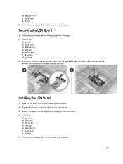
...the computer and remove it from the system board. Remove the: a) battery b) base cover c) keyboard trim d) keyboard e) optical drive f) hard drive g) palmrest 3. Follow the procedures in After Working Inside Your Computer. Remove the screws that secure the USH board to the system ...board. 4. Follow the procedures in After Working Inside Your Computer. 41 Install the: a) palmrest b) hard drive c) optical drive d) keyboard e) keyboard trim f) base cover g) battery 5. e) keyboard trim f) base cover g) battery 5. Removing the USH Board 1. Follow...
...the computer and remove it from the system board. Remove the: a) battery b) base cover c) keyboard trim d) keyboard e) optical drive f) hard drive g) palmrest 3. Follow the procedures in After Working Inside Your Computer. Remove the screws that secure the USH board to the system ...board. 4. Follow the procedures in After Working Inside Your Computer. 41 Install the: a) palmrest b) hard drive c) optical drive d) keyboard e) keyboard trim f) base cover g) battery 5. e) keyboard trim f) base cover g) battery 5. Removing the USH Board 1. Follow...
Owner's Manual
Page 42
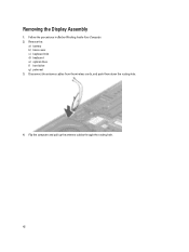
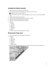
Flip the computer and pull up the antenna cables through the routing hole. 42 Follow the procedures in Before Working Inside Your Computer. 2. Remove the: a) battery b) base cover c) keyboard trim d) keyboard e) optical drive f) hard drive g) palmrest 3. Disconnect the antenna cables from the wireless cards, and push them down the routing hole. 4. Removing the Display Assembly 1.
Flip the computer and pull up the antenna cables through the routing hole. 42 Follow the procedures in Before Working Inside Your Computer. 2. Remove the: a) battery b) base cover c) keyboard trim d) keyboard e) optical drive f) hard drive g) palmrest 3. Disconnect the antenna cables from the wireless cards, and push them down the routing hole. 4. Removing the Display Assembly 1.
Owner's Manual
Page 45
... 1. Connect the camera and LVDS cables to secure the display assembly in M6700 only. 3. NOTE: LVDS cable is available in place. 2. Install the: a) palmrest b) hard drive c) optical drive d) keyboard e) keyboard trim f) base cover g) battery 9. Installing the Display Assembly 1. Route the cables through the routing hole on the system board. Tighten the screws at... and back of the computer. 7. Remove the screws that secure the hinge cover to the computer. Remove the: a) battery b) base cover c) keyboard trim d) keyboard e) optical drive f) hard drive g) display assembly 3.
... 1. Connect the camera and LVDS cables to secure the display assembly in M6700 only. 3. NOTE: LVDS cable is available in place. 2. Install the: a) palmrest b) hard drive c) optical drive d) keyboard e) keyboard trim f) base cover g) battery 9. Installing the Display Assembly 1. Route the cables through the routing hole on the system board. Tighten the screws at... and back of the computer. 7. Remove the screws that secure the hinge cover to the computer. Remove the: a) battery b) base cover c) keyboard trim d) keyboard e) optical drive f) hard drive g) display assembly 3.


