
User's Guide
Page 28
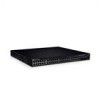
... 1000Base-X SFP Ports G3 G4 Stacking Ports 28 Hardware Description Designated as 1000Base-T ports • Console port - PowerConnect 3548 Port Description The PowerConnect 3548 device is prevented. The second button is the Reset Button which is used to select the unit number. There ...Figure 2-3. The Stack ID button is used to manually reset the device. RJ-45 ports designated as 10/100Base-T ports • 2 Fiber ports - The following figure illustrates the PowerConnect 3548 front panel. PowerConnect 3524 Back Panel Console Port RPS Connector Power Connector ...
... 1000Base-X SFP Ports G3 G4 Stacking Ports 28 Hardware Description Designated as 1000Base-T ports • Console port - PowerConnect 3548 Port Description The PowerConnect 3548 device is prevented. The second button is the Reset Button which is used to select the unit number. There ...Figure 2-3. The Stack ID button is used to manually reset the device. RJ-45 ports designated as 10/100Base-T ports • 2 Fiber ports - The following figure illustrates the PowerConnect 3548 front panel. PowerConnect 3524 Back Panel Console Port RPS Connector Power Connector ...

User's Guide
Page 29
... two buttons on the front panel. The baud rate can either be configured from 2400 bps up to select the unit number. PowerConnect 3548 Back Panel Console Port RPS Connector Power Connector The back panel contains an RPS connector, console port and power connector. They include ...TWSI (Two-Wire Serial Interface) and internal EPROM. G4 can be used to manually reset the device. The second button is used for a terminal connection is prevented. The default baud rate is marked with even numbers 2-...
... two buttons on the front panel. The baud rate can either be configured from 2400 bps up to select the unit number. PowerConnect 3548 Back Panel Console Port RPS Connector Power Connector The back panel contains an RPS connector, console port and power connector. They include ...TWSI (Two-Wire Serial Interface) and internal EPROM. G4 can be used to manually reset the device. The second button is used for a terminal connection is prevented. The default baud rate is marked with even numbers 2-...

User's Guide
Page 37
... unit is reset. Operation can be verified by power-up or low-voltage conditions. Ventilation System The PowerConnect 3524/P and PowerConnect 3548/P switches with the PoE feature have a reset button, located on the front panel, for manual reset of the switch is activated by observing the LED that indicates if one or more fans...
... unit is reset. Operation can be verified by power-up or low-voltage conditions. Ventilation System The PowerConnect 3524/P and PowerConnect 3548/P switches with the PoE feature have a reset button, located on the front panel, for manual reset of the switch is activated by observing the LED that indicates if one or more fans...

User's Guide
Page 46
... is a stand-alone unit, the Stack LED is stand-alone. The default setting is not illuminated. The unit ID is illuminated. 46 Installing the PowerConnect 3524/P and PowerConnect 3548/P Unit ID 1 and 2 are reserved for the Master and Backup Master unit, and unit ID 3 to 8 are for 15 seconds. When powering up, the... to flash. Figure 3-6. Stacking Configuration and Identification Panel Each stack device has a unique identifying unit ID that the stand-alone/Master device Console port is manually configured by the Stack ID LEDs.
... is a stand-alone unit, the Stack LED is stand-alone. The default setting is not illuminated. The unit ID is illuminated. 46 Installing the PowerConnect 3524/P and PowerConnect 3548/P Unit ID 1 and 2 are reserved for the Master and Backup Master unit, and unit ID 3 to 8 are for 15 seconds. When powering up, the... to flash. Figure 3-6. Stacking Configuration and Identification Panel Each stack device has a unique identifying unit ID that the stand-alone/Master device Console port is manually configured by the Stack ID LEDs.
User's Guide
Page 50
... up and running as quickly as possible. If this product. After the initial configuration, the device can skip the Setup Wizard, and manually configure the device through the device CLI mode. NOTE: Obtain the following information from the network administrator before configuring the device: •.../P and 3548/P You can be managed (by default, every port is to determine if the device is fully operational before and is in the same state as when you through the Console port. The Setup Wizard configures the following : • The Dell™ PowerConnect™ device was ...
... up and running as quickly as possible. If this product. After the initial configuration, the device can skip the Setup Wizard, and manually configure the device through the device CLI mode. NOTE: Obtain the following information from the network administrator before configuring the device: •.../P and 3548/P You can be managed (by default, every port is to determine if the device is fully operational before and is in the same state as when you through the Console port. The Setup Wizard configures the following : • The Dell™ PowerConnect™ device was ...
User's Guide
Page 51
...next question to run the setup wizard within 60 seconds, the Setup Wizard automatically exits and the CLI console prompt appears. Configuring PowerConnect 3524/P and 3548/P 51 The system will continue with a default answer; NOTE: If there is no response within 60 seconds, otherwise the ...address • Default Gateway IP address The following is displayed: The system is not setup for Dell Network Manager) you can skip the setup wizard, and enter CLI mode to manually configure the switch. If you enter [Y], the Setup Wizard provides interactive guidance through the initial ...
...next question to run the setup wizard within 60 seconds, the Setup Wizard automatically exits and the CLI console prompt appears. Configuring PowerConnect 3524/P and 3548/P 51 The system will continue with a default answer; NOTE: If there is no response within 60 seconds, otherwise the ...address • Default Gateway IP address The following is displayed: The system is not setup for Dell Network Manager) you can skip the setup wizard, and enter CLI mode to manually configure the switch. If you enter [Y], the Setup Wizard provides interactive guidance through the initial ...

User's Guide
Page 66
.... By default, this feature is disabled. The receiver may occupy a link so it becomes unavailable for additional traffic. 66 Configuring PowerConnect 3524/P and 3548/P MDI/MDIX The device supports auto-detection of speed, duplex mode and flow control on all switching 10/100/1000BaseT ports. Flow... is disabled. The ports then both the device switching port and the NIC must temporarily be enabled per port. It can be manually set to auto-negotiate with Crossover) is enabled, the automatic correction of the link attempts to auto-negotiation, both operate at the...
.... By default, this feature is disabled. The receiver may occupy a link so it becomes unavailable for additional traffic. 66 Configuring PowerConnect 3524/P and 3548/P MDI/MDIX The device supports auto-detection of speed, duplex mode and flow control on all switching 10/100/1000BaseT ports. Flow... is disabled. The ports then both the device switching port and the NIC must temporarily be enabled per port. It can be manually set to auto-negotiate with Crossover) is enabled, the automatic correction of the link attempts to auto-negotiation, both operate at the...


