
User's Guide
Page 4
... 29 Physical Dimensions 30 LED Definitions 30 Gigabit Port LEDs 32 System LEDs 33 Power Supplies 35 Stack ID Button 36 Reset Button 37 Ventilation System 37 3 Installing the PowerConnect 3524/P and PowerConnect 3548/P 39 Site Preparation 39 Unpacking 39 Package Contents 39 Unpacking the Device 40 Mounting the Device 40 Installing in a Rack...
... 29 Physical Dimensions 30 LED Definitions 30 Gigabit Port LEDs 32 System LEDs 33 Power Supplies 35 Stack ID Button 36 Reset Button 37 Ventilation System 37 3 Installing the PowerConnect 3524/P and PowerConnect 3548/P 39 Site Preparation 39 Unpacking 39 Package Contents 39 Unpacking the Device 40 Mounting the Device 40 Installing in a Rack...

User's Guide
Page 15
... not operating in stand-alone mode, the unit does not boot. For example, • If a PowerConnect 3524/P replaces PowerConnect 3524/P, all port configurations remain the same. • If a PowerConnect 3548/P replaces the PowerConnect 3548/P, all configured ports is saved, even if the stack is applied to configure the stack. Non-present ports...system. If the new inserted device has either more or fewer ports than the previous device, the relevant port configuration is reset and/or the ports are no longer present. Configuration files are configured through the CLI or SNMP interfaces.
... not operating in stand-alone mode, the unit does not boot. For example, • If a PowerConnect 3524/P replaces PowerConnect 3524/P, all port configurations remain the same. • If a PowerConnect 3548/P replaces the PowerConnect 3548/P, all configured ports is saved, even if the stack is applied to configure the stack. Non-present ports...system. If the new inserted device has either more or fewer ports than the previous device, the relevant port configuration is reset and/or the ports are no longer present. Configuration files are configured through the CLI or SNMP interfaces.

User's Guide
Page 28
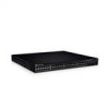
... - Designated as 10/100Base-T ports • 2 Fiber ports - The Stack ID button is configured with the following figure illustrates the PowerConnect 3548 front panel. PowerConnect 3548 Front Panel 10/100 Base-T Ports 1, 3, 5, 7, ...47 System LEDs Reset Button Stacking Button Stacking LEDs 10/100 Base-T Ports 2, 4, 6, 8, ...48 G1 G2 1000Base-X SFP Ports G3 G4 Stacking Ports...
... - Designated as 10/100Base-T ports • 2 Fiber ports - The Stack ID button is configured with the following figure illustrates the PowerConnect 3548 front panel. PowerConnect 3548 Front Panel 10/100 Base-T Ports 1, 3, 5, 7, ...47 System LEDs Reset Button Stacking Button Stacking LEDs 10/100 Base-T Ports 2, 4, 6, 8, ...48 G1 G2 1000Base-X SFP Ports G3 G4 Stacking Ports...

User's Guide
Page 29
...) and internal EPROM. Figure 2-5. The front panel contains 48 RJ-45 ports number 1-48. Ports G3- The following figure illustrates the PowerConnect 3548 back panel: Figure 2-4. Console Port Hardware Description 29 The baud rate can either be configured from 2400 bps up to forward network traffic ...in a stand-alone device. The Reset button does not extend beyond the unit's front panel surface, so reset by odd numbers 1-47, and the lower row of ports is marked by pressing it accidentally is 9,600 bps. PowerConnect 3548 Back Panel Console Port RPS Connector Power ...
...) and internal EPROM. Figure 2-5. The front panel contains 48 RJ-45 ports number 1-48. Ports G3- The following figure illustrates the PowerConnect 3548 back panel: Figure 2-4. Console Port Hardware Description 29 The baud rate can either be configured from 2400 bps up to forward network traffic ...in a stand-alone device. The Reset button does not extend beyond the unit's front panel surface, so reset by odd numbers 1-47, and the lower row of ports is marked by pressing it accidentally is 9,600 bps. PowerConnect 3548 Back Panel Console Port RPS Connector Power ...

User's Guide
Page 37
Ventilation System The PowerConnect 3524/P and PowerConnect 3548/P switches with the PoE feature have two built-in fans. Reset Button The PowerConnect 3524/P and PowerConnect 3548/P switches have a reset button, located on the front panel, for manual reset of the switch is activated by observing the LED that indicates if one or more fans is reset, the remain stacking members are...
Ventilation System The PowerConnect 3524/P and PowerConnect 3548/P switches with the PoE feature have two built-in fans. Reset Button The PowerConnect 3524/P and PowerConnect 3548/P switches have a reset button, located on the front panel, for manual reset of the switch is activated by observing the LED that indicates if one or more fans is reset, the remain stacking members are...
User's Guide
Page 54
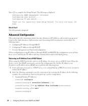
... displayed: Configuring SNMP management interface Configuring user account...... Retrieving an IP Address From a DHCP Server When using Dell Easy Setup Wizard. When the device is reset, the DHCP command is saved in order to retrieve the IP address. 2 Enter the following commands to ...: console# configure console(config)# interface ethernet 1/e1 console(config-if)# ip address dhcp hostname powerconnect console(config-if)# exit console(config)# 54 Configuring PowerConnect 3524/P and 3548/P To retrieve an IP address from these servers includes the IP address and may include subnet mask...
... displayed: Configuring SNMP management interface Configuring user account...... Retrieving an IP Address From a DHCP Server When using Dell Easy Setup Wizard. When the device is reset, the DHCP command is saved in order to retrieve the IP address. 2 Enter the following commands to ...: console# configure console(config)# interface ethernet 1/e1 console(config-if)# ip address dhcp hostname powerconnect console(config-if)# exit console(config)# 54 Configuring PowerConnect 3524/P and 3548/P To retrieve an IP address from these servers includes the IP address and may include subnet mask...

User's Guide
Page 56
This command will reset the whole system and disconnect your changes. Data encryption is lost, a password recovery procedure can be invoked from the Startup menu. The device receives the ... Authentication, Authorization, and Accounting (AAA) mechanism that manages user access rights, privileges, and management methods. The device reboots with no password entered. 56 Configuring PowerConnect 3524/P and 3548/P The procedure is applicable for the local terminal only and allows a one-time access to the device from the local terminal with no default...
This command will reset the whole system and disconnect your changes. Data encryption is lost, a password recovery procedure can be invoked from the Startup menu. The device receives the ... Authentication, Authorization, and Accounting (AAA) mechanism that manages user access rights, privileges, and management methods. The device reboots with no password entered. 56 Configuring PowerConnect 3524/P and 3548/P The procedure is applicable for the local terminal only and allows a one-time access to the device from the local terminal with no default...

User's Guide
Page 59
... technical support personnel only and are for the auto-boot message SYSTEM RESET Boot1 Checksum Test PASS Boot2 Checksum Test PASS Flash Image Validation Test PASS BOOT Software Version 1.0.0.05 Built 06-Jan-xxxx 14:46:49 Configuring PowerConnect 3524/P and 3548/P 59 To view and configure login banners: console# banner motd Welcome...
... technical support personnel only and are for the auto-boot message SYSTEM RESET Boot1 Checksum Test PASS Boot2 Checksum Test PASS Flash Image Validation Test PASS BOOT Software Version 1.0.0.05 Built 06-Jan-xxxx 14:46:49 Configuring PowerConnect 3524/P and 3548/P 59 To view and configure login banners: console# banner motd Welcome...

User's Guide
Page 64
...bootvar command to the device. Many periods in the boot system command is selected for the next boot. The device reboots. 64 Configuring PowerConnect 3524/P and 3548/P Each symbol (!) corresponds to continue (y/n) [n]? 8 Enter y. After this command, enter the show bootvar Images currently available on 176.215...symbols indicate that the copying process failed. 6 Select the image for the next boot is displayed: console# reload This command will reset the whole system and disconnect your current session. When the new image is downloaded, it is saved in the area allocated for ...
...bootvar command to the device. Many periods in the boot system command is selected for the next boot. The device reboots. 64 Configuring PowerConnect 3524/P and 3548/P Each symbol (!) corresponds to continue (y/n) [n]? 8 Enter y. After this command, enter the show bootvar Images currently available on 176.215...symbols indicate that the copying process failed. 6 Select the image for the next boot is displayed: console# reload This command will reset the whole system and disconnect your current session. When the new image is downloaded, it is saved in the area allocated for ...

User's Guide
Page 65
The following message is powered on. Configuring PowerConnect 3524/P and 3548/P 65 The boot image is loaded when the device is displayed: console# reload This command will reset the whole system and disconnect your current session. A user has no control over the boot image copies. Boot Image Download Loading a new boot image from ...
The following message is powered on. Configuring PowerConnect 3524/P and 3548/P 65 The boot image is loaded when the device is displayed: console# reload This command will reset the whole system and disconnect your current session. A user has no control over the boot image copies. Boot Image Download Loading a new boot image from ...


