
Microprocessor Upgrade Installation Guide
Page 3
...; Heat-sink retention clip(s) • A VRM, if applicable Your upgrade kit may also include a cooling fan. The following items are contained in a pin-grid array (PGA) package that is installed in your system. CAUTION: See "Protecting Against Electrostatic Discharge" in the safety instructions in the System Information document. 3 Remove the cooling shroud, if applicable (see your Installation and Troubleshooting Guide). Adding or Replacing...
...; Heat-sink retention clip(s) • A VRM, if applicable Your upgrade kit may also include a cooling fan. The following items are contained in a pin-grid array (PGA) package that is installed in your system. CAUTION: See "Protecting Against Electrostatic Discharge" in the safety instructions in the System Information document. 3 Remove the cooling shroud, if applicable (see your Installation and Troubleshooting Guide). Adding or Replacing...
Microprocessor Upgrade Installation Guide
Page 4
... your Installation and Troubleshooting Guide. 1-2 Microprocessor Upgrade Installation Guide NOTE: If a cooling fan is necessary to remove the microprocessor. CAUTION: The microprocessor and heat sink can permanently damage the microprocessor. 7 Unpack the new microprocessor. www.dell.com | support.dell.com 4 If you can remove the heat sink without removing the fan. NOTICE: Never remove the heat sink from being damaged or contaminated. Bending the pins can become extremely hot...
... your Installation and Troubleshooting Guide. 1-2 Microprocessor Upgrade Installation Guide NOTE: If a cooling fan is necessary to remove the microprocessor. CAUTION: The microprocessor and heat sink can permanently damage the microprocessor. 7 Unpack the new microprocessor. www.dell.com | support.dell.com 4 If you can remove the heat sink without removing the fan. NOTICE: Never remove the heat sink from being damaged or contaminated. Bending the pins can become extremely hot...

Microprocessor Upgrade Installation Guide
Page 5
..., be sure that all of the microprocessor and socket aligned, set the microprocessor lightly in the socket and ensure that the microprocessor socket release lever ...open position. Microprocessor Upgrade Installation Guide 1-3 Removing and Replacing the Microprocessor pin-1 locators microprocessor microprocessor socket NOTICE: Positioning the microprocessor incorrectly can permanently damage the microprocessor and the system when you turn on the microprocessor go into place, locking the microprocessor in the socket. c With pin 1 of the pins on the system. Be careful not to use...
..., be sure that all of the microprocessor and socket aligned, set the microprocessor lightly in the socket and ensure that the microprocessor socket release lever ...open position. Microprocessor Upgrade Installation Guide 1-3 Removing and Replacing the Microprocessor pin-1 locators microprocessor microprocessor socket NOTICE: Positioning the microprocessor incorrectly can permanently damage the microprocessor and the system when you turn on the microprocessor go into place, locking the microprocessor in the socket. c With pin 1 of the pins on the system. Be careful not to use...

Microprocessor Upgrade Installation Guide
Page 6
... thermal interface material, and then place the heat sink on the microprocessor. • If heat-sink thermal grease is provided with one of the VRMs from the upgrade kit. For information on installing a cooling fan, see Figure 1-2). NOTE: The system does not support mismatched VRMs. 1-4 Microprocessor Upgrade Installation Guide www.dell.com | support.dell.com 9 Install the heat sink. • If the heat sink provided has a protective cover...
... thermal interface material, and then place the heat sink on the microprocessor. • If heat-sink thermal grease is provided with one of the VRMs from the upgrade kit. For information on installing a cooling fan, see Figure 1-2). NOTE: The system does not support mismatched VRMs. 1-4 Microprocessor Upgrade Installation Guide www.dell.com | support.dell.com 9 Install the heat sink. • If the heat sink provided has a protective cover...
Microprocessor Upgrade Installation Guide
Page 7
... you access the inside of the new processor and automatically changes the system configuration information in the system's nonvolatile random-access memory (NVRAM). To clear this message log, see your Installation and Troubleshooting Guide for information about using the System Setup program, see your Installation and Troubleshooting Guide). 17 Reconnect your User's Guide. 19 Run the system diagnostics to be displayed at the next system startup. Microprocessor Upgrade Installation Guide 1-5 Figure 1-2. As the system boots, it detects the...
... you access the inside of the new processor and automatically changes the system configuration information in the system's nonvolatile random-access memory (NVRAM). To clear this message log, see your Installation and Troubleshooting Guide for information about using the System Setup program, see your Installation and Troubleshooting Guide). 17 Reconnect your User's Guide. 19 Run the system diagnostics to be displayed at the next system startup. Microprocessor Upgrade Installation Guide 1-5 Figure 1-2. As the system boots, it detects the...

Information Update (.pdf)
Page 5
... remotely manage and monitor your system's Embedded Remote Access Option (ERA/O) card. Installing an ERA/O Card CAUTION: Only trained service technicians are known as remote access controllers (RACs). NOTE: The Dell™ Remote Access Card III (DRAC III), DRAC III/XT, Embedded Remote Access (ERA), and the ERA/O are systems management hardware and software solutions designed to provide remote management capabilities for PowerEdge™ systems. Collectively, these solutions are authorized to remove the system cover and access...
... remotely manage and monitor your system's Embedded Remote Access Option (ERA/O) card. Installing an ERA/O Card CAUTION: Only trained service technicians are known as remote access controllers (RACs). NOTE: The Dell™ Remote Access Card III (DRAC III), DRAC III/XT, Embedded Remote Access (ERA), and the ERA/O are systems management hardware and software solutions designed to provide remote management capabilities for PowerEdge™ systems. Collectively, these solutions are authorized to remove the system cover and access...
Information Update (.pdf)
Page 6
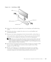
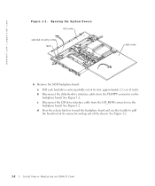
Opening the System Covers left cover optional security screw latch right cover 6 Remove the SCSI backplane board: a Pull each hard-drive carrier partially out of the chassis. b Disconnect the diskette-drive interface cable from the CD_ROM connector on the backplane board. See Figure 1-2. See Figure 1-2. d Press the release latch in toward the backplane board and use the handle to pull the board out of its connector and up out of its slot, approximately 2.5 cm...
Opening the System Covers left cover optional security screw latch right cover 6 Remove the SCSI backplane board: a Pull each hard-drive carrier partially out of the chassis. b Disconnect the diskette-drive interface cable from the CD_ROM connector on the backplane board. See Figure 1-2. See Figure 1-2. d Press the release latch in toward the backplane board and use the handle to pull the board out of its connector and up out of its slot, approximately 2.5 cm...
Information Update (.pdf)
Page 7
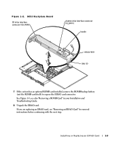
see "Removing an ERA/O Card" for removal instructions before continuing with the next step. Installing or Replacing an ERA/O Card 1-3 If you are replacing an ERA/O card, see also "Removing a ROMB Card" in your Installation and Troubleshooting Guide. 8 Unpack the ERA/O card. See Figure 1-3; SCSI Backplane Board CD drive interface connector (CD_ROM) diskette drive interface connector (FLOPPY) handle release latch tabs (2) 7 If the system has an optional ROMB card installed, remove the ROMB backup battery (not the ROMB card itself) to expose the ERA/O card connector. Figure 1-2.
see "Removing an ERA/O Card" for removal instructions before continuing with the next step. Installing or Replacing an ERA/O Card 1-3 If you are replacing an ERA/O card, see also "Removing a ROMB Card" in your Installation and Troubleshooting Guide. 8 Unpack the ERA/O card. See Figure 1-3; SCSI Backplane Board CD drive interface connector (CD_ROM) diskette drive interface connector (FLOPPY) handle release latch tabs (2) 7 If the system has an optional ROMB card installed, remove the ROMB backup battery (not the ROMB card itself) to expose the ERA/O card connector. Figure 1-2.

Information Update (.pdf)
Page 8
... backup battery ROMB card ERA/O card connector battery standoffs (2) RAID BATTERY connector 9 Install the ERA/O card in the ERA/O card connector (EMBEDDED_REMOTE_ ASSISTANT) on the system board. See Figure 1-4. align the holes along the edges of the four retention clips on the system board. a Align the connector on the bottom of the ERA/O card with the center posts of the card with the ERA/O connector on the system board; www.dell.com | support.dell...
... backup battery ROMB card ERA/O card connector battery standoffs (2) RAID BATTERY connector 9 Install the ERA/O card in the ERA/O card connector (EMBEDDED_REMOTE_ ASSISTANT) on the system board. See Figure 1-4. align the holes along the edges of the four retention clips on the system board. a Align the connector on the bottom of the ERA/O card with the center posts of the card with the ERA/O connector on the system board; www.dell.com | support.dell...
Information Update (.pdf)
Page 9
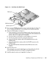
.../O card connector retention clips (4) 10 If you removed a ROMB backup battery in your Installation and Troubleshooting Guide. 11 Replace the SCSI backplane. e Connect the diskette-drive interface cable to seat the backplane in the chassis. See Figure 1-1. also see "Installing a ROMB Card" in step 7, replace the battery. b Press down firmly over the handle to the FLOPPY connector on the backplane board. See Figure 1-2. d Connect the CD drive interface cable to snap the securing latch into the securing slot...
.../O card connector retention clips (4) 10 If you removed a ROMB backup battery in your Installation and Troubleshooting Guide. 11 Replace the SCSI backplane. e Connect the diskette-drive interface cable to seat the backplane in the chassis. See Figure 1-1. also see "Installing a ROMB Card" in step 7, replace the battery. b Press down firmly over the handle to the FLOPPY connector on the backplane board. See Figure 1-2. d Connect the CD drive interface cable to snap the securing latch into the securing slot...

Information Update (.pdf)
Page 10
... been used before, you must remove the thin plastic cover that protects the connector. Figure 1-5. www.dell.com | support.dell.com 14 Reconnect the system and peripherals to their electrical outlets, and turn them on. 15 Install the optional front bezel (if applicable). 16 If the 100-Mbps RAC Ethernet connector on the documentation CD for the location of the connector. 17 Connect a network cable to...
... been used before, you must remove the thin plastic cover that protects the connector. Figure 1-5. www.dell.com | support.dell.com 14 Reconnect the system and peripherals to their electrical outlets, and turn them on. 15 Install the optional front bezel (if applicable). 16 If the 100-Mbps RAC Ethernet connector on the documentation CD for the location of the connector. 17 Connect a network cable to...

Information Update (.pdf)
Page 11
Removing an ERA/O Card CAUTION: Only trained service technicians are authorized to remove the system cover and access any of the card from the RAC Ethernet connector (if applicable). Installing or Replacing an ERA/O Card 1-7 See Figure 1-4. 3 Push open the remaining two retention clips and remove the card completely. 4 Perform steps 10-15 in "Installing an ERA/O Card." 2 Push open the two retention clips nearest the ERA/O card connector while...
Removing an ERA/O Card CAUTION: Only trained service technicians are authorized to remove the system cover and access any of the card from the RAC Ethernet connector (if applicable). Installing or Replacing an ERA/O Card 1-7 See Figure 1-4. 3 Push open the remaining two retention clips and remove the card completely. 4 Perform steps 10-15 in "Installing an ERA/O Card." 2 Push open the two retention clips nearest the ERA/O card connector while...

Installation and Troubleshooting Guide (.htm)
Page 5
... Instructions 1-1 Rack Mounting of Systems 1-1 Installation Instructions 1-2 Rack Requirements for VersaRails 1-3 Four-Post Rack Installation 1-3 Before You Begin 1-3 Recommended Tools and Supplies 1-3 RapidRails Rack Kit Contents 1-4 VersaRails Rack Kit Contents 1-4 Installation Tasks 1-5 Removing the Rack Doors 1-5 Marking the Rack 1-6 Installing the RapidRails Slide Assemblies 1-7 Installing the VersaRails Slide Assemblies 1-9 Installing the System in the Rack 1-10 Installing the Cable-Management Arm 1-11 Routing Cables 1-14 Replacing the Rack Doors 1-16 Two-Post Rack...
... Instructions 1-1 Rack Mounting of Systems 1-1 Installation Instructions 1-2 Rack Requirements for VersaRails 1-3 Four-Post Rack Installation 1-3 Before You Begin 1-3 Recommended Tools and Supplies 1-3 RapidRails Rack Kit Contents 1-4 VersaRails Rack Kit Contents 1-4 Installation Tasks 1-5 Removing the Rack Doors 1-5 Marking the Rack 1-6 Installing the RapidRails Slide Assemblies 1-7 Installing the VersaRails Slide Assemblies 1-9 Installing the System in the Rack 1-10 Installing the Cable-Management Arm 1-11 Routing Cables 1-14 Replacing the Rack Doors 1-16 Two-Post Rack...
Installation and Troubleshooting Guide (.htm)
Page 6
...-Mount Configuration Installing the Stiffening Bracket (shown in the Rack (RapidRails or VersaRails Installing the Cable-Management Arm . . . Opening the Wire Covers Installing the Power Cord Strain Relief . . . RapidRails Rack Kit Contents VersaRails Rack Kit Contents One Rack Unit Marking the Vertical Rails Installing the RapidRails Slide Assemblies . . . Figure 1-7. Figure 1-9. Figure 1-13. Figure 1-8. Figure 1-17. Figure 1-3. Figure 1-12. Figure 1-15. Figure 1-18. Routing Cables Two-Post Rack Kit Components Two-Post, Open-Frame Relay Rack...
...-Mount Configuration Installing the Stiffening Bracket (shown in the Rack (RapidRails or VersaRails Installing the Cable-Management Arm . . . Opening the Wire Covers Installing the Power Cord Strain Relief . . . RapidRails Rack Kit Contents VersaRails Rack Kit Contents One Rack Unit Marking the Vertical Rails Installing the RapidRails Slide Assemblies . . . Figure 1-7. Figure 1-9. Figure 1-13. Figure 1-8. Figure 1-17. Figure 1-3. Figure 1-12. Figure 1-15. Figure 1-18. Routing Cables Two-Post Rack Kit Components Two-Post, Open-Frame Relay Rack...

Installation and Troubleshooting Guide (.htm)
Page 8
... servicing other components in damage to the system and personal injury to yourself and to others. 1-2 Rack Installation Guide This guide includes procedures for another system. Using the rack kit for the following rack kits: • RapidRails kit in a four-post rack cabinet • VersaRails kit in a four-post rack cabinet • Two-post kit (installed in either center-mount or flush-mount configuration) For ease in an open-frame relay rack. Use only the rack kit...
... servicing other components in damage to the system and personal injury to yourself and to others. 1-2 Rack Installation Guide This guide includes procedures for another system. Using the rack kit for the following rack kits: • RapidRails kit in a four-post rack cabinet • VersaRails kit in a four-post rack cabinet • Two-post kit (installed in either center-mount or flush-mount configuration) For ease in an open-frame relay rack. Use only the rack kit...
Installation and Troubleshooting Guide (.htm)
Page 9
... the rack cabinet. Use extreme caution while moving the rack cabinet. One rack kit is required for use in marking the mounting holes to be installed by trained service technicians in a rack that is intended to be used Rack Installation Guide 1-3 Avoid long or steep inclines or ramps where loss of American National Standards Institute (ANSI)/Electronic Industries Association (EIA) standard ANSI/EIA-310-D-92, International...
... the rack cabinet. Use extreme caution while moving the rack cabinet. One rack kit is required for use in marking the mounting holes to be installed by trained service technicians in a rack that is intended to be used Rack Installation Guide 1-3 Avoid long or steep inclines or ramps where loss of American National Standards Institute (ANSI)/Electronic Industries Association (EIA) standard ANSI/EIA-310-D-92, International...
Installation and Troubleshooting Guide (.htm)
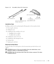
Page 11
...-head status-indicator cable Phillips screws (10) Installation Tasks Installing a rack kit involves performing the following tasks in their numbered order: 1 Removing the rack doors 2 Marking the rack 3 Installing the slide assemblies in the rack • RapidRails slide assemblies • VersaRails slide assemblies 4 Installing the system in the rack 5 Installing the cable-management arm 6 Routing cables 7 Replacing the rack doors Removing the Rack Doors See the procedures for removing doors in the documentation provided...
...-head status-indicator cable Phillips screws (10) Installation Tasks Installing a rack kit involves performing the following tasks in their numbered order: 1 Removing the rack doors 2 Marking the rack 3 Installing the slide assemblies in the rack • RapidRails slide assemblies • VersaRails slide assemblies 4 Installing the system in the rack 5 Installing the cable-management arm 6 Routing cables 7 Replacing the rack doors Removing the Rack Doors See the procedures for removing doors in the documentation provided...

Installation and Troubleshooting Guide (.htm)
Page 19
... part of the arm. The wire cover swings open position status indicator Rack Installation Guide 1-13 4 Install a stop block. 5 Install the status-indicator cable plug into its load of installed cables. The stop blocks: one for right-side mounting and one for left-side mounting. The rack kit has two stop block prevents the cable-management arm from moving backward and supports the weight of the arm with its connector. 6 Open the wire covers...
... part of the arm. The wire cover swings open position status indicator Rack Installation Guide 1-13 4 Install a stop block. 5 Install the status-indicator cable plug into its load of installed cables. The stop blocks: one for right-side mounting and one for left-side mounting. The rack kit has two stop block prevents the cable-management arm from moving backward and supports the weight of the arm with its connector. 6 Open the wire covers...

Installation and Troubleshooting Guide (.htm)
Page 20
... system back. For details on cable connections, see your system's Installation and Troubleshooting Guide and the User's Guide. 1-14 Rack Installation Guide Figure 1-10. Installing the Power Cord Strain Relief power cord strain-relief tab and tie wrap power receptacle housing power cord plug Routing Cables 1 Attach the I/O cable connectors to 19 mm (0.75 inch), the system manufacturer recommends that you only use the power cords provided with a bend radius...
... system back. For details on cable connections, see your system's Installation and Troubleshooting Guide and the User's Guide. 1-14 Rack Installation Guide Figure 1-10. Installing the Power Cord Strain Relief power cord strain-relief tab and tie wrap power receptacle housing power cord plug Routing Cables 1 Attach the I/O cable connectors to 19 mm (0.75 inch), the system manufacturer recommends that you only use the power cords provided with a bend radius...

Installation and Troubleshooting Guide (.htm)
Page 22
... place. www.dell.com | support.dell.com Replacing the Rack Doors Refer to mark the mounting holes 1-16 Rack Installation Guide Two-Post Rack Installation The two-post rack kit is used to others may result. Damage to the system and personal injury to yourself and to install a system in a two-post, open -frame relay rack manufacturer's installation documentation for replacing doors in telecommunications equipment facilities. See the two-post, open -frame relay rack, such as...
... place. www.dell.com | support.dell.com Replacing the Rack Doors Refer to mark the mounting holes 1-16 Rack Installation Guide Two-Post Rack Installation The two-post rack kit is used to others may result. Damage to the system and personal injury to yourself and to install a system in a two-post, open -frame relay rack manufacturer's installation documentation for replacing doors in telecommunications equipment facilities. See the two-post, open -frame relay rack, such as...


