
Installing a SATA Optical Drive
Page 3
... release the blue tab at the top of the peripheral bay and remove the optical drive from the back of the optical drive. 6 PowerEdge 2900 and 1900 systems only: Perform the following steps. a Disconnect the SAS cable from the SAS controller and pull the cable away from the...the bezel. All Systems 1 Turn off the system and attached peripherals, and disconnect the system from the center fan bracket. Installing a SATA Optical Drive These instructions apply to Dell™ PowerEdge™ systems to remove the system cover and access any of the components inside the system. See "Opening ...
... release the blue tab at the top of the peripheral bay and remove the optical drive from the back of the optical drive. 6 PowerEdge 2900 and 1900 systems only: Perform the following steps. a Disconnect the SAS cable from the SAS controller and pull the cable away from the...the bezel. All Systems 1 Turn off the system and attached peripherals, and disconnect the system from the center fan bracket. Installing a SATA Optical Drive These instructions apply to Dell™ PowerEdge™ systems to remove the system cover and access any of the components inside the system. See "Opening ...

Installing a SATA Optical Drive
Page 6
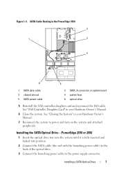
... toward the chipset shroud and insert the cable into position. 2 Connect the SATA cable (the end with a cable provided in the fan bracket and follow the power cable routing to the SATA_A connector on the system board. Figure 1-2. NOTE: You may need to replace the... system until it is fully inserted and locked into the cable path on the system board. 6 Installing a SATA Optical Drive Installing a SATA Optical Drive in a PowerEdge 1950 Drive Tray 2 3 1 4 5 1 optical drive 3 SATA power cable 5 optical drive carrier 2 SATA cable 4 carrier latch Installing the SATA Optical Drive...
... toward the chipset shroud and insert the cable into position. 2 Connect the SATA cable (the end with a cable provided in the fan bracket and follow the power cable routing to the SATA_A connector on the system board. Figure 1-2. NOTE: You may need to replace the... system until it is fully inserted and locked into the cable path on the system board. 6 Installing a SATA Optical Drive Installing a SATA Optical Drive in a PowerEdge 1950 Drive Tray 2 3 1 4 5 1 optical drive 3 SATA power cable 5 optical drive carrier 2 SATA cable 4 carrier latch Installing the SATA Optical Drive...
Installing a SATA Optical Drive
Page 7
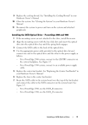
...system. SATA Cable Routing in your Hardware Owner's Manual. 7 Reconnect the system to the power supply connector. See "SAS Controller Daughter Card" in the PowerEdge 1950 2 1 3 4 6 5 1 SATA data cable 3 chipset shroud 5 SATA power cable 2 SATA_A connector on the system and attached peripherals. Installing the SATA Optical Drive... branching power cable) to the back of the optical drive. 3 Connect the branching power cable to power and turn on system board 4 system fans 6 optical drive 5 Reinstall the SAS controller daughter card and reconnect the SAS cable. Figure 1-3.
...system. SATA Cable Routing in your Hardware Owner's Manual. 7 Reconnect the system to the power supply connector. See "SAS Controller Daughter Card" in the PowerEdge 1950 2 1 3 4 6 5 1 SATA data cable 3 chipset shroud 5 SATA power cable 2 SATA_A connector on the system and attached peripherals. Installing the SATA Optical Drive... branching power cable) to the back of the optical drive. 3 Connect the branching power cable to power and turn on system board 4 system fans 6 optical drive 5 Reinstall the SAS controller daughter card and reconnect the SAS cable. Figure 1-3.
Installing a SATA Optical Drive
Page 9
... SATA_D connector. Installing a SATA Optical Drive 9 For a PowerEdge 1900 system, connect to power and turn on the system backplane. See "Closing the System" in your Hardware Owner's Manual. 11 Reconnect the system to an available power supply cable. 5 Replace the center fan bracket. For a PowerEdge 2900 system, connect to the power supply as follows...
... SATA_D connector. Installing a SATA Optical Drive 9 For a PowerEdge 1900 system, connect to power and turn on the system backplane. See "Closing the System" in your Hardware Owner's Manual. 11 Reconnect the system to an available power supply cable. 5 Replace the center fan bracket. For a PowerEdge 2900 system, connect to the power supply as follows...

Getting Started Guide
Page 5
... DIMMs (FBD), upgradable to two hot-pluggable, 930-W power supplies in a 1 + 1 redundant configuration. • Six hot-pluggable system cooling fans. A full-height TBU is available if eight or twelve identical memory modules are data only. • An intrusion switch that supports multiprocessing. SMP ...improves overall system performance by installing a second processor, you must order the processor upgrade kits from Dell contains the correct version of the processor, heat sink, and fan as well as additional processors. To take advantage of this feature, you must use an operating ...
... DIMMs (FBD), upgradable to two hot-pluggable, 930-W power supplies in a 1 + 1 redundant configuration. • Six hot-pluggable system cooling fans. A full-height TBU is available if eight or twelve identical memory modules are data only. • An intrusion switch that supports multiprocessing. SMP ...improves overall system performance by installing a second processor, you must order the processor upgrade kits from Dell contains the correct version of the processor, heat sink, and fan as well as additional processors. To take advantage of this feature, you must use an operating ...

Getting Started Guide
Page 6
slot 3 is 1600 x 1200 with 64 K colors; See support.dell.com for the latest support information about specific features, see "Technical Specifications" on the front and back panels. This video subsystem contains 16 MB of the system fans as well as critical system voltages and temperatures. true-color graphics are supported in an...
slot 3 is 1600 x 1200 with 64 K colors; See support.dell.com for the latest support information about specific features, see "Technical Specifications" on the front and back panels. This video subsystem contains 16 MB of the system fans as well as critical system voltages and temperatures. true-color graphics are supported in an...
Hardware Owner's Manual (PDF)
Page 5
Removing the Power Supply Blank 64 Installing the Power Supply Blank 64 Fans 64 Removing and Installing a Fan 65 Removing or Installing the Cooling Shroud Fan 66 Expansion Cards 68 Installing an Expansion Card 68 Removing an Expansion Card 70 Internal SCSI Tape Backup Unit 70... Shroud 79 Removing the Cooling Shroud 79 Installing the Cooling Shroud 81 Fan Brackets 81 Removing the Center Fan Bracket 81 Replacing the Center Fan Bracket 81 Removing the Back Fan Bracket 82 Replacing the Back Fan Bracket 82 Memory 82 General Memory Module Installation Guidelines 84 Non-Optimal ...
Removing the Power Supply Blank 64 Installing the Power Supply Blank 64 Fans 64 Removing and Installing a Fan 65 Removing or Installing the Cooling Shroud Fan 66 Expansion Cards 68 Installing an Expansion Card 68 Removing an Expansion Card 70 Internal SCSI Tape Backup Unit 70... Shroud 79 Removing the Cooling Shroud 79 Installing the Cooling Shroud 81 Fan Brackets 81 Removing the Center Fan Bracket 81 Replacing the Center Fan Bracket 81 Removing the Back Fan Bracket 82 Replacing the Back Fan Bracket 82 Memory 82 General Memory Module Installation Guidelines 84 Non-Optimal ...

Hardware Owner's Manual (PDF)
Page 7
... a NIC 120 Troubleshooting a Wet System 120 Troubleshooting a Damaged System 121 Troubleshooting the System Battery 122 Troubleshooting Power Supplies 122 Troubleshooting System Cooling Problems 123 Troubleshooting a Fan 123 Troubleshooting System Memory 124 Troubleshooting a Diskette Drive 126 Troubleshooting an Optical Drive 127 Troubleshooting an External SCSI Tape Drive 128 Troubleshooting a Hard Drive 129...
... a NIC 120 Troubleshooting a Wet System 120 Troubleshooting a Damaged System 121 Troubleshooting the System Battery 122 Troubleshooting Power Supplies 122 Troubleshooting System Cooling Problems 123 Troubleshooting a Fan 123 Troubleshooting System Memory 124 Troubleshooting a Diskette Drive 126 Troubleshooting an Optical Drive 127 Troubleshooting an External SCSI Tape Drive 128 Troubleshooting a Hard Drive 129...

Hardware Owner's Manual (PDF)
Page 19
...Call Support Temp Ambient E1116 Temp Memory E1210 CMOS Batt E1211 ROMB Batt E12nn XX PwrGd E1229 CPU # VCORE E1310 RPM Fan ## E1313 Fan Redundancy Causes Corrective Actions A 62-character string that can change the system string The SYSTEM NAME displays in the System only...CMOS battery is missing, or the See "Troubleshooting the System voltage is for redundant. Processor # VCORE voltage regulator has failed. Another fan failure additional scrolling messages. Controller Daughter Card Battery" on page 96, and "Troubleshooting System Cooling Problems" on page 122. "Troubleshooting ...
...Call Support Temp Ambient E1116 Temp Memory E1210 CMOS Batt E1211 ROMB Batt E12nn XX PwrGd E1229 CPU # VCORE E1310 RPM Fan ## E1313 Fan Redundancy Causes Corrective Actions A 62-character string that can change the system string The SYSTEM NAME displays in the System only...CMOS battery is missing, or the See "Troubleshooting the System voltage is for redundant. Processor # VCORE voltage regulator has failed. Another fan failure additional scrolling messages. Controller Daughter Card Battery" on page 96, and "Troubleshooting System Cooling Problems" on page 122. "Troubleshooting ...

Hardware Owner's Manual (PDF)
Page 26
... code on the screen to notify you of messages indicating multiple voltage faults, you receive a series of a possible problem with sensors, such as temperature, voltage, fans, and so on the status LCD, locate the code in Table 1-6 and perform the suggested corrective action. You perform this task from the system management...
... code on the screen to notify you of messages indicating multiple voltage faults, you receive a series of a possible problem with sensors, such as temperature, voltage, fans, and so on the status LCD, locate the code in Table 1-6 and perform the suggested corrective action. You perform this task from the system management...

Hardware Owner's Manual (PDF)
Page 33
... management software documentation. Record the message on page 147, and then follow the instructions in that accompanied the operating system or application. Table 1-7. Dell recommends a population of the Diagnostics Checklist in "Getting Help" on a copy of 2, 4, 8, or 12 DIMMs. DIMMs should be populated... but nonoptimal population of an abbreviation or acronym used in this table, see the documentation that section for drive, temperature, fan, and power conditions. See "Memory" on page 169. Diagnostics Messages When you may result. Alert Messages Systems management software...
... management software documentation. Record the message on page 147, and then follow the instructions in that accompanied the operating system or application. Table 1-7. Dell recommends a population of the Diagnostics Checklist in "Getting Help" on a copy of 2, 4, 8, or 12 DIMMs. DIMMs should be populated... but nonoptimal population of an abbreviation or acronym used in this table, see the documentation that section for drive, temperature, fan, and power conditions. See "Memory" on page 169. Diagnostics Messages When you may result. Alert Messages Systems management software...
Hardware Owner's Manual (PDF)
Page 49
Installing System Components This section describes how to install the following system components: • Hot-plug hard drives • Power supplies • Cooling fans • Expansion cards • Tape, optical, and diskette drives • System battery • System memory • RAC card • Microprocessors • SAS backplane board • ...
Installing System Components This section describes how to install the following system components: • Hot-plug hard drives • Power supplies • Cooling fans • Expansion cards • Tape, optical, and diskette drives • System battery • System memory • RAC card • Microprocessors • SAS backplane board • ...

Hardware Owner's Manual (PDF)
Page 53
... from the system. To avoid injury, do not attempt to lift the system by yourself. 1 Unless you are installing a hot-plug component such as a cooling fan or power supply, turn the latch release lock on the right (or bottom) side of the chassis. See Figure 3-4. 3 Push the latch down to lever...
... from the system. To avoid injury, do not attempt to lift the system by yourself. 1 Unless you are installing a hot-plug component such as a cooling fan or power supply, turn the latch release lock on the right (or bottom) side of the chassis. See Figure 3-4. 3 Push the latch down to lever...

Hardware Owner's Manual (PDF)
Page 64
... Using a Phillips screwdriver, remove the screw on the left side of the blank into the power supply bay and secure with a particular fan, the fan's number is referenced by the systems management software, allowing you are installing a second power supply. Installing the Power Supply Blank To install ... blank only if you to clear the bay, and remove from the chassis. Figure 3-11 shows the positions and identification numbers of the fans. 64 Installing System Components NOTICE: To ensure proper system cooling, the power supply blank must be installed on top of a problem with ...
... Using a Phillips screwdriver, remove the screw on the left side of the blank into the power supply bay and secure with a particular fan, the fan's number is referenced by the systems management software, allowing you are installing a second power supply. Installing the Power Supply Blank To install ... blank only if you to clear the bay, and remove from the chassis. Figure 3-11 shows the positions and identification numbers of the fans. 64 Installing System Components NOTICE: To ensure proper system cooling, the power supply blank must be installed on top of a problem with ...
Hardware Owner's Manual (PDF)
Page 65
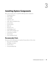
... data. 3 To replace the fan, align the connector on top of the fan and lift the fan out of time. The fan will start when it seats into the fan bracket. Cooling Fans 1 3 2 4 5 6 1 expansion-card fan (FAN1) 4 memory module fan (FAN4) 2 processor fan (FAN2) 5 memory module fan (FAN5) 3 processor fan (FAN3) 6 memory module fan (FAN6) Removing and Installing a Fan CAUTION: Only trained service...
... data. 3 To replace the fan, align the connector on top of the fan and lift the fan out of time. The fan will start when it seats into the fan bracket. Cooling Fans 1 3 2 4 5 6 1 expansion-card fan (FAN1) 4 memory module fan (FAN4) 2 processor fan (FAN2) 5 memory module fan (FAN5) 3 processor fan (FAN3) 6 memory module fan (FAN6) Removing and Installing a Fan CAUTION: Only trained service...
Hardware Owner's Manual (PDF)
Page 66
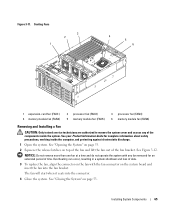
...the loss of the components inside the computer, and protecting against electrostatic discharge. See "Removing the Bezel" on each side of the fan bracket, and then rotate the bracket to remove the system cover and access any of data. 1 Remove the front bezel, if ...13. NOTICE: Never remove the memory cooling shroud without first powering down the system. Installing and Removing a Fan From the Fan Brackets 1 2 3 4 1 fan 4 fan connector on page 53. 3 Release the fan bracket from the system to perform this step. 66 Installing System Components Figure 3-12. See your Product ...
...the loss of the components inside the computer, and protecting against electrostatic discharge. See "Removing the Bezel" on each side of the fan bracket, and then rotate the bracket to remove the system cover and access any of data. 1 Remove the front bezel, if ...13. NOTICE: Never remove the memory cooling shroud without first powering down the system. Installing and Removing a Fan From the Fan Brackets 1 2 3 4 1 fan 4 fan connector on page 53. 3 Release the fan bracket from the system to perform this step. 66 Installing System Components Figure 3-12. See your Product ...
Hardware Owner's Manual (PDF)
Page 67
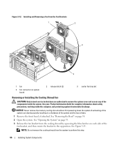
Removing and Replacing the Cooling Shroud Fan 1 2 3 5 1 fan 4 fan bracket latch (2) 4 2 fan release latch (2) 5 fan bracket 3 cooling shroud Installing System Components 67 Overheating can occur resulting in a system shutdown and loss of data. 5 Replace the fan. 6 Rotate the fan bracket toward the shroud and slightly squeeze the side tabs so ...that the tabs enter the latch slots. 7 Close the system. NOTICE: Do not remove more than one fan from the bracket by squeezing the release handles on page 53. 8 Replace the front bezel, if removed. See "Closing the System...
Removing and Replacing the Cooling Shroud Fan 1 2 3 5 1 fan 4 fan bracket latch (2) 4 2 fan release latch (2) 5 fan bracket 3 cooling shroud Installing System Components 67 Overheating can occur resulting in a system shutdown and loss of data. 5 Replace the fan. 6 Rotate the fan bracket toward the shroud and slightly squeeze the side tabs so ...that the tabs enter the latch slots. 7 Close the system. NOTICE: Do not remove more than one fan from the bracket by squeezing the release handles on page 53. 8 Replace the front bezel, if removed. See "Closing the System...

Hardware Owner's Manual (PDF)
Page 73
... the system, including any attached peripherals, and disconnect the system from the SAS controller daughter card on the peripheral bay. See "Removing the Center Fan Bracket" on page 53. 15 Replace the front bezel, if removed in step 2. 16 Reconnect the system and peripherals to the SAS controller daughter.... 4 Remove the filler plate from the drive slot on the expansion-bay bracket and pull the cables out of the way of the center fans. 5 Remove the fans from the electrical outlet. 2 Remove the front bezel, if attached. See "Closing the System" on page 81. 7 Push the spring latch at ...
... the system, including any attached peripherals, and disconnect the system from the SAS controller daughter card on the peripheral bay. See "Removing the Center Fan Bracket" on page 53. 15 Replace the front bezel, if removed in step 2. 16 Reconnect the system and peripherals to the SAS controller daughter.... 4 Remove the filler plate from the drive slot on the expansion-bay bracket and pull the cables out of the way of the center fans. 5 Remove the fans from the electrical outlet. 2 Remove the front bezel, if attached. See "Closing the System" on page 81. 7 Push the spring latch at ...

Hardware Owner's Manual (PDF)
Page 74
...-quarters of the way into the drive slot on the peripheral bay, with the mounting screws entering the bay slide slots. See "Removing the Center Fan Bracket" on page 81. 8 If the mounting screws are authorized to the power connector on the rear of the optical drive. 12 Push the ...optical drive the rest of the center fans. 6 Remove the fans from the center fan bracket. a Push inward on the plastic tab on the side of the components inside the computer, and protecting against electrostatic discharge. 1 ...
...-quarters of the way into the drive slot on the peripheral bay, with the mounting screws entering the bay slide slots. See "Removing the Center Fan Bracket" on page 81. 8 If the mounting screws are authorized to the power connector on the rear of the optical drive. 12 Push the ...optical drive the rest of the center fans. 6 Remove the fans from the center fan bracket. a Push inward on the plastic tab on the side of the components inside the computer, and protecting against electrostatic discharge. 1 ...

Hardware Owner's Manual (PDF)
Page 76
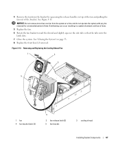
...inside the computer, and protecting against electrostatic discharge. 1 Turn off the system, including any of the center fan bracket. See "Removing and Installing a Fan" on page 81. 76 Installing System Components Installing the Diskette Drive Into the Drive Carrier Place the diskette drive...holes, and secure with the three Phillips screws. See "Opening the System" on page 50. 3 Open the system. c Remove the center fan bracket. See "Removing the Center Fan Bracket" on page 65. Installing the Diskette Drive Into the Drive Carrier 1 2 3 4 1 screws (3) 4 diskette drive 2 diskette ...
...inside the computer, and protecting against electrostatic discharge. 1 Turn off the system, including any of the center fan bracket. See "Removing and Installing a Fan" on page 81. 76 Installing System Components Installing the Diskette Drive Into the Drive Carrier Place the diskette drive...holes, and secure with the three Phillips screws. See "Opening the System" on page 50. 3 Open the system. c Remove the center fan bracket. See "Removing the Center Fan Bracket" on page 65. Installing the Diskette Drive Into the Drive Carrier 1 2 3 4 1 screws (3) 4 diskette drive 2 diskette ...


