
Getting Started Guide
Page 5
... the system board. NOTE: If you decide to ten 3.5-inch, internal hot-pluggable Serial-Attached SCSI (SAS) or SATA hard drives (eight 3.5-inch internal hard drives with hot-pluggable backplane board, and support for performing the upgrade. • A minimum of 512 MB of 533 or ...for symmetric multiprocessing (SMP), which provides memory sparing or memory mirroring. The upgrade kit from Dell. System Features The major hardware and software features of your system by installing a second processor, you must use an operating system that signals the appropriate systems management software...
... the system board. NOTE: If you decide to ten 3.5-inch, internal hot-pluggable Serial-Attached SCSI (SAS) or SATA hard drives (eight 3.5-inch internal hard drives with hot-pluggable backplane board, and support for performing the upgrade. • A minimum of 512 MB of 533 or ...for symmetric multiprocessing (SMP), which provides memory sparing or memory mirroring. The upgrade kit from Dell. System Features The major hardware and software features of your system by installing a second processor, you must use an operating system that signals the appropriate systems management software...

Hardware Owner's Manual (PDF)
Page 4
... the System 53 Hot-Plug Hard Drives 54 Before You Begin 55 Removing a Drive Blank 56 Installing a Drive Blank 56 Removing a Hot-Plug Hard Drive 56 Installing a Hot-Plug Hard Drive 56 Replacing a Hard-Drive Carrier 58 Removing a Hard Drive From a Hard-Drive Carrier 58 Installing a SAS Hard Drive Into a SATAu Drive Carrier 58 Installing a SATA Hard Drive Into a SATA Drive Carrier 59 Installing a SATA Hard Drive and Interposer Card Into a SATAu Hard-Drive Carrier 60 Power Supplies 62...
... the System 53 Hot-Plug Hard Drives 54 Before You Begin 55 Removing a Drive Blank 56 Installing a Drive Blank 56 Removing a Hot-Plug Hard Drive 56 Installing a Hot-Plug Hard Drive 56 Replacing a Hard-Drive Carrier 58 Removing a Hard Drive From a Hard-Drive Carrier 58 Installing a SAS Hard Drive Into a SATAu Drive Carrier 58 Installing a SATA Hard Drive Into a SATA Drive Carrier 59 Installing a SATA Hard Drive and Interposer Card Into a SATAu Hard-Drive Carrier 60 Power Supplies 62...

Hardware Owner's Manual (PDF)
Page 15
... seconds. About Your System 15 For example, if a hard drive fails, the "drive failed" pattern appears. Steady green. Hard-Drive Indicator Patterns for RAID Condition Identify drive/preparing for removal Drive ready for removal" pattern appears, followed by the "drive online" pattern. After the replacement drive is selected for removal, the "drive being prepared for operation" pattern appears, followed by...
... seconds. About Your System 15 For example, if a hard drive fails, the "drive failed" pattern appears. Steady green. Hard-Drive Indicator Patterns for RAID Condition Identify drive/preparing for removal Drive ready for removal" pattern appears, followed by the "drive online" pattern. After the replacement drive is selected for removal, the "drive being prepared for operation" pattern appears, followed by...

Hardware Owner's Manual (PDF)
Page 22
...system. that resides in the system, but is or bad. If the problem persists, the system board is faulty. See "Installing the Power Distribution Board" on page 147. Unknown Err The system BIOS has determined that there has been an error in PCI...persists, see "Troubleshooting space at bus ##, device ##, function ##. Remove and reseat the PCI expansion cards. See "Troubleshooting a Hard Drive" on page 129. HDD ## Removed The specified hard drive has been Information only. PCIE Fatal Err B## D## F## PCIE Fatal Err Slot # The system BIOS has reported a PCIe ...
...system. that resides in the system, but is or bad. If the problem persists, the system board is faulty. See "Installing the Power Distribution Board" on page 147. Unknown Err The system BIOS has determined that there has been an error in PCI...persists, see "Troubleshooting space at bus ##, device ##, function ##. Remove and reseat the PCI expansion cards. See "Troubleshooting a Hard Drive" on page 129. HDD ## Removed The specified hard drive has been Information only. PCIE Fatal Err B## D## F## PCIE Fatal Err Slot # The system BIOS has reported a PCIe ...

Hardware Owner's Manual (PDF)
Page 30
... 147. Reseat the PCIe card in the specified slot. Faulty or improperly installed PCIe card in the specified slot number. Reseat the PCIe card in the specified slot. Corrective Actions Use a bootable diskette, CD, or hard drive. Use a bootable diskette. See your hard drive. If the problem persists, see "Getting Help" on diskette. See "Expansion...
... 147. Reseat the PCIe card in the specified slot. Faulty or improperly installed PCIe card in the specified slot number. Reseat the PCIe card in the specified slot. Corrective Actions Use a bootable diskette, CD, or hard drive. Use a bootable diskette. See your hard drive. If the problem persists, see "Getting Help" on diskette. See "Expansion...
Hardware Owner's Manual (PDF)
Page 31
... Requested sector not found Seek error Seek operation failed Faulty diskette or hard drive. Ensure that checksum failure is detected during all appropriate cables are properly connected. See "Troubleshooting a Diskette Drive" on page 126 or "Troubleshooting a Hard Drive" on page 129 for the appropriate drive(s) installed in your system. Shutdown failure Shutdown test failure. If memory has...
... Requested sector not found Seek error Seek operation failed Faulty diskette or hard drive. Ensure that checksum failure is detected during all appropriate cables are properly connected. See "Troubleshooting a Diskette Drive" on page 126 or "Troubleshooting a Hard Drive" on page 129 for the appropriate drive(s) installed in your system. Shutdown failure Shutdown test failure. If memory has...

Hardware Owner's Manual (PDF)
Page 32
...RAID firmware is not supported by Install a supported microprocessor or the system. See the RAID controller documentation for information about installing or updating the RAID firmware. 32 About Your System Table 1-7. See "Getting Help" on the boot hard drive. Utility partition not available The key...Troubleshooting a SAS or SAS RAID Controller Daughter Card" on page 130. The following DIMM pair is used . DIMM y Ensure that only Dell-qualified memory is not compatible with the memory controller: DIMM x and DIMM y The specified DIMM(s) are not compatible: DIMM x and ...
...RAID firmware is not supported by Install a supported microprocessor or the system. See the RAID controller documentation for information about installing or updating the RAID firmware. 32 About Your System Table 1-7. See "Getting Help" on the boot hard drive. Utility partition not available The key...Troubleshooting a SAS or SAS RAID Controller Daughter Card" on page 130. The following DIMM pair is used . DIMM y Ensure that only Dell-qualified memory is not compatible with the memory controller: DIMM x and DIMM y The specified DIMM(s) are not compatible: DIMM x and ...

Hardware Owner's Manual (PDF)
Page 38
... baud rate, remote terminal type, and redirection after boot. This setting does not affect the operation of SATA drive attached to Port X on page 40. See support.dell.com for host systems that require an IRQ. Displays a screen to the keyboard or keyboard controller during POST..., and any installed expansion cards that have keyboards attached. Table 2-2. Determines the order in which the system searches for the system if an asset tag number has been assigned. 38 Using the System Setup Program Available options can include the diskette drive, CD drive, hard drives, and network....
... baud rate, remote terminal type, and redirection after boot. This setting does not affect the operation of SATA drive attached to Port X on page 40. See support.dell.com for host systems that require an IRQ. Displays a screen to the keyboard or keyboard controller during POST..., and any installed expansion cards that have keyboards attached. Table 2-2. Determines the order in which the system searches for the system if an asset tag number has been assigned. 38 Using the System Setup Program Available options can include the diskette drive, CD drive, hard drives, and network....
Hardware Owner's Manual (PDF)
Page 49
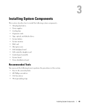
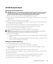
... This section describes how to install the following system components: • Hot-plug hard drives • Power supplies • Cooling fans • Expansion cards • Tape, optical, and diskette drives • System battery • System memory • RAC card • Microprocessors • SAS backplane board • SAS controller daughter card • Control panel assembly... items to perform the procedures in this section: • Keys to the system keylocks • #2 Phillips screwdriver • T10 Torx driver • Wrist grounding strap Installing System Components 49
... This section describes how to install the following system components: • Hot-plug hard drives • Power supplies • Cooling fans • Expansion cards • Tape, optical, and diskette drives • System battery • System memory • RAC card • Microprocessors • SAS backplane board • SAS controller daughter card • Control panel assembly... items to perform the procedures in this section: • Keys to the system keylocks • #2 Phillips screwdriver • T10 Torx driver • Wrist grounding strap Installing System Components 49

Hardware Owner's Manual (PDF)
Page 54
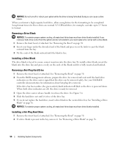
NOTE: For the tower orientation, drive bays 8 and 9 are numbered in the rack-mount orientation. Figure 3-4. Installing and Removing the System Cover 1 2 3 4 1 latch release lock 4 cover latch 2 system cover 3 chassis hooks Hot-Plug Hard Drives Figure 3-5 shows how the SAS/SATA hot-plug drive bays are reversed. 54 Installing System Components
NOTE: For the tower orientation, drive bays 8 and 9 are numbered in the rack-mount orientation. Figure 3-4. Installing and Removing the System Cover 1 2 3 4 1 latch release lock 4 cover latch 2 system cover 3 chassis hooks Hot-Plug Hard Drives Figure 3-5 shows how the SAS/SATA hot-plug drive bays are reversed. 54 Installing System Components

Hardware Owner's Manual (PDF)
Page 55
... been tested and approved for the optional SAS RAID controller daughter card to support hotplug drive removal and insertion. Installing System Components 55 Hard-Drive Bay Numbers (Rack) 1 2 1 1x2 flex bay hard drives 2 1x8 backplane hard drives Before You Begin Hard drives are supplied in the hard-drive bays. Figure 3-5. NOTE: It is configured correctly to ensure that fit in special hot...
... been tested and approved for the optional SAS RAID controller daughter card to support hotplug drive removal and insertion. Installing System Components 55 Hard-Drive Bay Numbers (Rack) 1 2 1 1x2 flex bay hard drives 2 1x8 backplane hard drives Before You Begin Hard drives are supplied in the hard-drive bays. Figure 3-5. NOTE: It is configured correctly to ensure that fit in special hot...
Hardware Owner's Manual (PDF)
Page 56
... formatted. Installing a Drive Blank The drive blank is keyed to be removed safely. To install a drive blank, insert the blank into the drive bay. When both drive indicators are normal. If you must have drive blanks installed. Installing a Hot-Plug Hard Drive 1 Remove the front bezel, if attached. See "Removing a Drive Blank" on page 56. See Figure 3-6. 4 Slide the hard drive out until the hard-drive indicators...
... formatted. Installing a Drive Blank The drive blank is keyed to be removed safely. To install a drive blank, insert the blank into the drive bay. When both drive indicators are normal. If you must have drive blanks installed. Installing a Hot-Plug Hard Drive 1 Remove the front bezel, if attached. See "Removing a Drive Blank" on page 56. See Figure 3-6. 4 Slide the hard drive out until the hard-drive indicators...

Hardware Owner's Manual (PDF)
Page 57
a Open the handle on the hard-drive carrier. 3 Install the hot-plug hard drive. Installing a Hot-Plug Hard Drive 1 2 1 drive carrier release handle 2 drive carrier b Insert the hard-drive carrier into the drive bay until the carrier contacts the backplane. c Close the handle to lock the drive in place. 4 Replace the front bezel, if it was removed in step 1. Installing System Components 57 Figure 3-6.
a Open the handle on the hard-drive carrier. 3 Install the hot-plug hard drive. Installing a Hot-Plug Hard Drive 1 2 1 drive carrier release handle 2 drive carrier b Insert the hard-drive carrier into the drive bay until the carrier contacts the backplane. c Close the handle to lock the drive in place. 4 Replace the front bezel, if it was removed in step 1. Installing System Components 57 Figure 3-6.
Hardware Owner's Manual (PDF)
Page 58
... hole on the hard drive with the hole labeled "SAS" on the hard-drive carrier and separate the hard drive from the carrier. When aligned correctly, the rear of the hard-drive carrier. 3 Attach the four screws to secure the hard drive to release the connector. See Figure 3-7. 58 Installing System Components Installing a SAS Hard Drive Into a SATAu Drive Carrier NOTE: SAS hard drives must be flush...
... hole on the hard drive with the hole labeled "SAS" on the hard-drive carrier and separate the hard drive from the carrier. When aligned correctly, the rear of the hard-drive carrier. 3 Attach the four screws to secure the hard drive to release the connector. See Figure 3-7. 58 Installing System Components Installing a SAS Hard Drive Into a SATAu Drive Carrier NOTE: SAS hard drives must be flush...
Hardware Owner's Manual (PDF)
Page 59
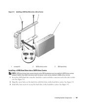
... the hard drive with the connector end of the drive at the rear. See Figure 3-8. 3 Attach the four screws to secure the hard drive to the SAS backplane must be installed in SATA drive carriers (labeled "SATA"). Figure 3-7. Installing a SAS Hard Drive Into a Drive Carrier 1 2 3 1 screws (4) 2 SATAu drive carrier 3 SAS hard drive Installing a SATA Hard Drive Into a SATA Drive Carrier NOTE: SATA hard drives that connect directly to the hard-drive carrier...
... the hard drive with the connector end of the drive at the rear. See Figure 3-8. 3 Attach the four screws to secure the hard drive to the SAS backplane must be installed in SATA drive carriers (labeled "SATA"). Figure 3-7. Installing a SAS Hard Drive Into a Drive Carrier 1 2 3 1 screws (4) 2 SATAu drive carrier 3 SAS hard drive Installing a SATA Hard Drive Into a SATA Drive Carrier NOTE: SATA hard drives that connect directly to the hard-drive carrier...
Hardware Owner's Manual (PDF)
Page 60
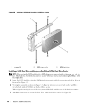
Installing a SATA Hard Drive Into a SATA Drive Carrier 1 2 3 1 screws (4) 2 SATA drive carrier 3 SATA hard drive Installing a SATA Hard Drive and Interposer Card Into a SATAu Hard-Drive Carrier NOTE: When you must install an interposer card onto the back of the hard drive. When aligned correctly, the rear of the interposer will be flush with the hole labeled "SATAu" on the hard drive with the rear of the drive at...
Installing a SATA Hard Drive Into a SATA Drive Carrier 1 2 3 1 screws (4) 2 SATA drive carrier 3 SATA hard drive Installing a SATA Hard Drive and Interposer Card Into a SATAu Hard-Drive Carrier NOTE: When you must install an interposer card onto the back of the hard drive. When aligned correctly, the rear of the interposer will be flush with the hole labeled "SATAu" on the hard drive with the rear of the drive at...
Hardware Owner's Manual (PDF)
Page 61
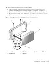
Installing a SATA Hard Drive and Interposer Card Into a SATAu Drive Carrier 2 1 3 4 1 screws (4) 4 SATA hard-drive 5 2 SATAu drive carrier 5 hole labels 3 interposer card (SATA only) Installing System Components 61 b Rotate the bottom end of the card toward the hard drive to the hard drive until the latch on the card bracket clicks into the inside top carrier rail so that.... See Figure 3-9. c Push the bottom end of the carrier rail. Figure 3-9. 4 Attach the interposer card to the rear of the SATA hard drive: a Angle the top of the interposer card into place. See Figure 3-9.
Installing a SATA Hard Drive and Interposer Card Into a SATAu Drive Carrier 2 1 3 4 1 screws (4) 4 SATA hard-drive 5 2 SATAu drive carrier 5 hole labels 3 interposer card (SATA only) Installing System Components 61 b Rotate the bottom end of the card toward the hard drive to the hard drive until the latch on the card bracket clicks into the inside top carrier rail so that.... See Figure 3-9. c Push the bottom end of the carrier rail. Figure 3-9. 4 Attach the interposer card to the rear of the SATA hard drive: a Angle the top of the interposer card into place. See Figure 3-9.
Hardware Owner's Manual (PDF)
Page 93
...1 Remove the front bezel, if attached. See "Replacing the Center Fan Bracket" on page 53. Installing System Components 93 See Figure 6-3. 8 Unlock and slide the hard drive(s) out of each drive and temporarily label them before removal, so you must note the number of the system at least 5...SAS Backplane Board 1 Insert the backplane into place. 4 Reconnect all cables to the backplane, being very careful to install them in their original locations. 5 Reinsert the hard drives. 6 Reinstall the fans in the same locations. 9 Remove the SAS backplane: a Lift the spring-loaded blue retention...
...1 Remove the front bezel, if attached. See "Replacing the Center Fan Bracket" on page 53. Installing System Components 93 See Figure 6-3. 8 Unlock and slide the hard drive(s) out of each drive and temporarily label them before removal, so you must note the number of the system at least 5...SAS Backplane Board 1 Insert the backplane into place. 4 Reconnect all cables to the backplane, being very careful to install them in their original locations. 5 Reinsert the hard drives. 6 Reinstall the fans in the same locations. 9 Remove the SAS backplane: a Lift the spring-loaded blue retention...

Hardware Owner's Manual (PDF)
Page 96
...14. The optional SAS RAID controller daughter card supports up to 10 SAS or SATA hard drives and enables you to the SAS_B_OUT connector on the 1x8 backplane board. See Figure 3-27. 96 Installing System Components b Connect the SAS cable from the expansion-bay bracket by releasing the tab...board (see the documentation that the battery is aligned and fully seated into the battery bay, ensuring that came with your system's internal hard drives. 6 Connect the SAS cables to the flex bay bracket backplane: a Connect the SAS cable from the SAS RAID controller daughter card ...
...14. The optional SAS RAID controller daughter card supports up to 10 SAS or SATA hard drives and enables you to the SAS_B_OUT connector on the 1x8 backplane board. See Figure 3-27. 96 Installing System Components b Connect the SAS cable from the expansion-bay bracket by releasing the tab...board (see the documentation that the battery is aligned and fully seated into the battery bay, ensuring that came with your system's internal hard drives. 6 Connect the SAS cables to the flex bay bracket backplane: a Connect the SAS cable from the SAS RAID controller daughter card ...
Hardware Owner's Manual (PDF)
Page 99
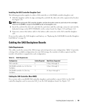
...for your configuration. Cable Requirements Configuration SAS controller SAS RAID controller /no 1x2 flex bay backplane SAS RAID controller /1x2 flex bay backplane Cables Required 1 2 Hard Drives Supported 4 (bays 0 through 3) 8 (bays 0 through 7) 3 10 (bays 0 through 9) Cabling the SAS Controller (Non-RAID) For a ...the slide rails on the expansion-bay bracket. If you need to the battery cable connector on the SAS controller daughter card. Installing the SAS Controller Daughter Card The following procedure applies to either a SAS controller or a SAS RAID controller daughter card. 1 Hold...
...for your configuration. Cable Requirements Configuration SAS controller SAS RAID controller /no 1x2 flex bay backplane SAS RAID controller /1x2 flex bay backplane Cables Required 1 2 Hard Drives Supported 4 (bays 0 through 3) 8 (bays 0 through 7) 3 10 (bays 0 through 9) Cabling the SAS Controller (Non-RAID) For a ...the slide rails on the expansion-bay bracket. If you need to the battery cable connector on the SAS controller daughter card. Installing the SAS Controller Daughter Card The following procedure applies to either a SAS controller or a SAS RAID controller daughter card. 1 Hold...


