Getting Started Guide
Page 10
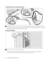
Bend the system power cable into a loop as shown in the illustration and attach to the bracket's cable clasp. Turning on the System Turn on the system and the monitor. The power indicators should light. Adjust the monitor's controls until the displayed image is satisfactory. 8 Getting Started With Your System Repeat the procedure for the second power supply. Press the power button on the system and monitor (optional). Installing the Power Cord Retention Bracket Attach the power cord retention bracket on the right bend of the power supply handle.
Bend the system power cable into a loop as shown in the illustration and attach to the bracket's cable clasp. Turning on the System Turn on the system and the monitor. The power indicators should light. Adjust the monitor's controls until the displayed image is satisfactory. 8 Getting Started With Your System Repeat the procedure for the second power supply. Press the power button on the system and monitor (optional). Installing the Power Cord Retention Bracket Attach the power cord retention bracket on the right bend of the power supply handle.
Hardware Owner's Manual (PDF)
Page 12
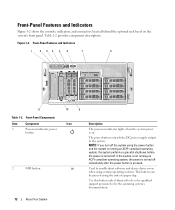
...and Indicators 1 2 34 5 6 7 8 11 Table 1-2. Front-Panel Components Item Component 1 Power-on indicator, power button 2 NMI button 10 9 Icon Description The power-on indicator lights when the system power is on the system's front panel. Front-Panel Features and Indicators Figure 1-2 shows the controls, ...driver errors when using certain operating systems. This button can be pressed using the power button and the system is running an ACPI-compliant operating system, the power is turned off immediately after the power button is turned off the system using the end...
...and Indicators 1 2 34 5 6 7 8 11 Table 1-2. Front-Panel Components Item Component 1 Power-on indicator, power button 2 NMI button 10 9 Icon Description The power-on indicator lights when the system power is on the system's front panel. Front-Panel Features and Indicators Figure 1-2 shows the controls, ...driver errors when using certain operating systems. This button can be pressed using the power button and the system is running an ACPI-compliant operating system, the power is turned off immediately after the power button is turned off the system using the end...
Hardware Owner's Manual (PDF)
Page 13
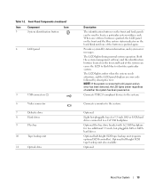
...whether the system has been powered on the back blink until one of the system can be used to identify a particular system. Connects USB 2.0-compliant devices to the system. About Your System 13 Both the system management software and the identification buttons located on the front ... 6 Video connector 7 Diskette drive 8 Hard drives 9 Flex bay 10 Tape backup unit 11 Optical drive Description The identification buttons on the front and back of the buttons is pushed, the LCD panel on the front and the blue system status indicator on . Provides system ID, status information, ...
...whether the system has been powered on the back blink until one of the system can be used to identify a particular system. Connects USB 2.0-compliant devices to the system. About Your System 13 Both the system management software and the identification buttons located on the front ... 6 Video connector 7 Diskette drive 8 Hard drives 9 Flex bay 10 Tape backup unit 11 Optical drive Description The identification buttons on the front and back of the buttons is pushed, the LCD panel on the front and the blue system status indicator on . Provides system ID, status information, ...
Hardware Owner's Manual (PDF)
Page 16
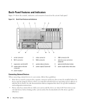
... 11 10 9 8 1 serial connector 4 NIC1 connector 7 expansion-card slots (6) 10 system status indicator connector 13 power supply 1 2 video connector 5 NIC2 connector 8 system status indicator 11 power supply 2 (optional) 3 USB connectors (4) 6 remote access connector (optional) 9 system identification button 12 power supply status indicators Connecting External Devices When connecting external devices to your system, follow these...
... 11 10 9 8 1 serial connector 4 NIC1 connector 7 expansion-card slots (6) 10 system status indicator connector 13 power supply 1 2 video connector 5 NIC2 connector 8 system status indicator 11 power supply 2 (optional) 3 USB connectors (4) 6 remote access connector (optional) 9 system identification button 12 power supply status indicators Connecting External Devices When connecting external devices to your system, follow these...
Hardware Owner's Manual (PDF)
Page 17
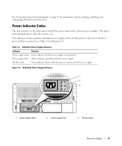
... power button on page 35 for information about enabling, disabling, and configuring I/O ports and connectors. Redundant Power Supply Indicators Indicator Function Power supply status Green indicates that a valid AC source is operational. See "Using the System Setup Program" on the front panel controls the power input to the power supply. Table 1-4. Redundant Power Supply Indicators 1 2 3 1 power supply status 2 power...
... power button on page 35 for information about enabling, disabling, and configuring I/O ports and connectors. Redundant Power Supply Indicators Indicator Function Power supply status Green indicates that a valid AC source is operational. See "Using the System Setup Program" on the front panel controls the power input to the power supply. Table 1-4. Redundant Power Supply Indicators 1 2 3 1 power supply status 2 power...
Hardware Owner's Manual (PDF)
Page 42
...; Return to Enabled prevents the system password from being changed or disabled at system start -up by using the power button, even if the Power Button option is enabled in the System Setup program. When set to Unlocked. Exit Screen After you cannot change the password...system, the system can only turn on the system after power is restored to Off, the system remains off immediately after power is restored. System Security Screen Options (continued) Option Password Status Power Button NMI Button AC Power Recovery (Last default) Description Setting the Setup Password option...
...; Return to Enabled prevents the system password from being changed or disabled at system start -up by using the power button, even if the Power Button option is enabled in the System Setup program. When set to Unlocked. Exit Screen After you cannot change the password...system, the system can only turn on the system after power is restored to Off, the system remains off immediately after power is restored. System Security Screen Options (continued) Option Password Status Power Button NMI Button AC Power Recovery (Last default) Description Setting the Setup Password option...

Hardware Owner's Manual (PDF)
Page 169
...Interchange. Glossary 169 ACPI - application - ASCII - asset tag - BIOS - Basic input/output system. C - Celsius. AC - Advanced Configuration and Power Interface. A program that keeps a copy of your system, back up important start-up your system if the system will not boot from the hard... an address bus and a data bus for enabling the operating system to help you must restart the system by pressing the reset button or by pressing . Applications run from your system. Your system's BIOS contains programs stored on . blade - Compact disc. ANSI...
...Interchange. Glossary 169 ACPI - application - ASCII - asset tag - BIOS - Basic input/output system. C - Celsius. AC - Advanced Configuration and Power Interface. A program that keeps a copy of your system, back up important start-up your system if the system will not boot from the hard... an address bus and a data bus for enabling the operating system to help you must restart the system by pressing the reset button or by pressing . Applications run from your system. Your system's BIOS contains programs stored on . blade - Compact disc. ANSI...

Hardware Owner's Manual (PDF)
Page 170
...DC - A technology in a hierarchical, "inverted tree" structure. Others must be loaded from the config.sys file or as the power button and power indicator. Deutsche Industrie Norm. Dynamic random-access memory. EEPROM - ERA allows you start the program for the serial ports on your system...to a client system. Electromagnetic interference. Each component is usually made up entirely of translating Internet domain names, such as www.dell.com, into an expansion-card connector on a disk in memory modules that relieves the system's processor of data between the...
...DC - A technology in a hierarchical, "inverted tree" structure. Others must be loaded from the config.sys file or as the power button and power indicator. Deutsche Industrie Norm. Dynamic random-access memory. EEPROM - ERA allows you start the program for the serial ports on your system...to a client system. Electromagnetic interference. Each component is usually made up entirely of translating Internet domain names, such as www.dell.com, into an expansion-card connector on a disk in memory modules that relieves the system's processor of data between the...
Hardware Owner's Manual (PDF)
Page 179
...26 warning, 33 microprocessor replacing, 89 troubleshooting, 133 mirroring memory, 85 mouse troubleshooting, 118 N NICs indicators, 18 troubleshooting, 120 NMI button, 12 O opening the system, 53 optical drive installing, 73 removing, 73 options CPU setup, 39 integrated devices, 40 system security... peripheral bay panel installing, 52 removing, 52 POST accessing system features, 11 power indicator, 17 power distribution board installing, 112 removing, 110 power supply installing, 63 removing, 62 troubleshooting, 122 power supply blank, 64 processor replacing, 89 R RAC card installing, 87 RAID ...
...26 warning, 33 microprocessor replacing, 89 troubleshooting, 133 mirroring memory, 85 mouse troubleshooting, 118 N NICs indicators, 18 troubleshooting, 120 NMI button, 12 O opening the system, 53 optical drive installing, 73 removing, 73 options CPU setup, 39 integrated devices, 40 system security... peripheral bay panel installing, 52 removing, 52 POST accessing system features, 11 power indicator, 17 power distribution board installing, 112 removing, 110 power supply installing, 63 removing, 62 troubleshooting, 122 power supply blank, 64 processor replacing, 89 R RAC card installing, 87 RAID ...
Hardware Owner's Manual (PDF)
Page 180
...features, 11 status messages LCD, 18 systems management, 26 support contacting Dell, 152 system board connectors, 141 installing, 109 jumpers, 139 removing, 107 system cooling troubleshooting, 123 system features accessing, 11 system identification button, 13 system messages, 26 system password assigning, 43 changing, 45...drive from a drive carrier, 58 hard drives, 56 memory, 87 optical drive, 73 peripheral bay panel (tower), 52 power distribution board, 110 power supply, 62 power supply blank, 64 processor, 89 rack bezel, 50 SAS backplane board (1x8), 93 SAS controller daughter card, 97 system...
...features, 11 status messages LCD, 18 systems management, 26 support contacting Dell, 152 system board connectors, 141 installing, 109 jumpers, 139 removing, 107 system cooling troubleshooting, 123 system features accessing, 11 system identification button, 13 system messages, 26 system password assigning, 43 changing, 45...drive from a drive carrier, 58 hard drives, 56 memory, 87 optical drive, 73 peripheral bay panel (tower), 52 power distribution board, 110 power supply, 62 power supply blank, 64 processor, 89 rack bezel, 50 SAS backplane board (1x8), 93 SAS controller daughter card, 97 system...


