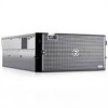

Installing a SATA Optical Drive
Page 3
... your Hardware Owner's Manual. 4 PowerEdge 1950 systems only: Disconnect and remove the SAS controller daughter card. c Release the spring latch at the top of the peripheral bay and remove the optical drive from the back of the optical drive. 6 PowerEdge 2900 and 1900 systems only: Perform the... from the electrical outlet. 2 Remove the bezel. Installing a SATA Optical Drive 3 Installing a SATA Optical Drive These instructions apply to Dell™ PowerEdge™ systems to remove the system cover and access any of the system. Removing an Existing Optical Drive - b Remove the center ...
... your Hardware Owner's Manual. 4 PowerEdge 1950 systems only: Disconnect and remove the SAS controller daughter card. c Release the spring latch at the top of the peripheral bay and remove the optical drive from the back of the optical drive. 6 PowerEdge 2900 and 1900 systems only: Perform the... from the electrical outlet. 2 Remove the bezel. Installing a SATA Optical Drive 3 Installing a SATA Optical Drive These instructions apply to Dell™ PowerEdge™ systems to remove the system cover and access any of the system. Removing an Existing Optical Drive - b Remove the center ...
Installing a SATA Optical Drive
Page 4
... system is used for the SATA optical drive. The PowerEdge 2900 and 1900 systems do not reuse the interposer board attached to the old drive. 1 Pull outward on the interposer board release tab at the back of the drive tray to release the interposer board connected to the optical drive. The..., and 1950 For PowerEdge 2970 and 2950 systems, the optical drive tray that shipped with the SATA drive installation kit. See Figure 1-1. 5 Lower the left side of the optical drive to separate the drive from the tray. 3 Pull outward again on the interposer board release tab and simultaneously pull...
... system is used for the SATA optical drive. The PowerEdge 2900 and 1900 systems do not reuse the interposer board attached to the old drive. 1 Pull outward on the interposer board release tab at the back of the drive tray to release the interposer board connected to the optical drive. The..., and 1950 For PowerEdge 2970 and 2950 systems, the optical drive tray that shipped with the SATA drive installation kit. See Figure 1-1. 5 Lower the left side of the optical drive to separate the drive from the tray. 3 Pull outward again on the interposer board release tab and simultaneously pull...

Installing a SATA Optical Drive
Page 5
...2970 System 2 1 3 4 5 6 7 1 optical drive 3 interposer 5 SATA power cable 7 optical drive carrier 2 interposer release latch 4 SATA cable 6 carrier latch Replacing a PowerEdge 1950 Optical Drive NOTE: The replacement drive tray provided in the side of the SATA optical drive into the tray until the pins ...on the carrier align with the holes in the installation kit must be used with PowerEdge 1950 systems. If you are replacing an existing optical drive, do not reuse the interposer board attached to the tray. Installing a SATA Optical...
...2970 System 2 1 3 4 5 6 7 1 optical drive 3 interposer 5 SATA power cable 7 optical drive carrier 2 interposer release latch 4 SATA cable 6 carrier latch Replacing a PowerEdge 1950 Optical Drive NOTE: The replacement drive tray provided in the side of the SATA optical drive into the tray until the pins ...on the carrier align with the holes in the installation kit must be used with PowerEdge 1950 systems. If you are replacing an existing optical drive, do not reuse the interposer board attached to the tray. Installing a SATA Optical...

Installing a SATA Optical Drive
Page 8
...Cooling Shroud" in your Hardware Owner's Manual. 5 Remove the cable retention bracket from the right interior wall of the chassis by pushing the blue release latch and sliding the bracket toward the front of the system until the bracket detaches from the chassis slots. 6 Route the SATA cable in ...the cable channel in the PowerEdge 2950 and 2970 1 2 3 4 5 1 SATA_B connector on the system board. See Figure 1-4. 7 Route the SATA cable along the top of the chassis and replace...
...Cooling Shroud" in your Hardware Owner's Manual. 5 Remove the cable retention bracket from the right interior wall of the chassis by pushing the blue release latch and sliding the bracket toward the front of the system until the bracket detaches from the chassis slots. 6 Route the SATA cable in ...the cable channel in the PowerEdge 2950 and 2970 1 2 3 4 5 1 SATA_B connector on the system board. See Figure 1-4. 7 Route the SATA cable along the top of the chassis and replace...

Getting Started Guide
Page 7
... to provide last-minute updates to the system or documentation or advanced technical reference material intended for configuring and managing your system. • Release notes or readme files may not be included within this guide or if the system does not perform as a separate document. •... is available; This section describes the steps to a stand-alone tower system. The illustrations that came with your system or on support.dell.com. • CDs included with your system on installing the stabilizer feet on the CDs that follow the safety instructions and important regulatory...
... to provide last-minute updates to the system or documentation or advanced technical reference material intended for configuring and managing your system. • Release notes or readme files may not be included within this guide or if the system does not perform as a separate document. •... is available; This section describes the steps to a stand-alone tower system. The illustrations that came with your system or on support.dell.com. • CDs included with your system on installing the stabilizer feet on the CDs that follow the safety instructions and important regulatory...

Hardware Owner's Manual (PDF)
Page 11
...PXE support enabled through the System Setup Program (see "Integrated Devices Screen" on support.dell.com and read the updates first because they often supersede information in other documents. • Release notes or readme files may be included to provide last-minute updates to the system... information on setup and use of DRAC. Enters the Baseboard Management Controller (BMC) Management Utility, which allows you have the optional Dell Remote Access Controller (DRAC), this keystroke allows access to configure an optional RAID card. Option is displayed only if you to selected...
...PXE support enabled through the System Setup Program (see "Integrated Devices Screen" on support.dell.com and read the updates first because they often supersede information in other documents. • Release notes or readme files may be included to provide last-minute updates to the system... information on setup and use of DRAC. Enters the Baseboard Management Controller (BMC) Management Utility, which allows you have the optional Dell Remote Access Controller (DRAC), this keystroke allows access to configure an optional RAID card. Option is displayed only if you to selected...
Hardware Owner's Manual (PDF)
Page 50
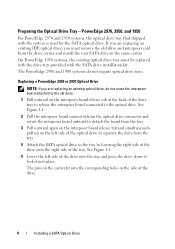
... the Optional Bezel (Rack) 1 1 key lock 2 3 2 bezel (rack) 3 bezel slot (2) 50 Installing System Components See Figure 3-1. Figure 3-1. See Figure 3-1. 2 While grasping the bezel, press the release latch on the left edge of the bezel. Opening and Closing the System The system is enclosed by an optional bezel and cover. To upgrade...
... the Optional Bezel (Rack) 1 1 key lock 2 3 2 bezel (rack) 3 bezel slot (2) 50 Installing System Components See Figure 3-1. Figure 3-1. See Figure 3-1. 2 While grasping the bezel, press the release latch on the left edge of the bezel. Opening and Closing the System The system is enclosed by an optional bezel and cover. To upgrade...
Hardware Owner's Manual (PDF)
Page 51
See Figure 3-2. See Figure 3-2. 2 While grasping the bezel, push the release latch on top of bezel to the left. 3 Rotate the top of the bezel away from the system. Removing the Tower Bezel 1 Unlock the keylock at the right side of the bezel and pull the bezel away from the front panel. 4 Unhook the bottom of the bezel. Figure 3-2. Installing and Removing the Optional Bezel (Tower) 1 2 1 bezel 4 bezel latch 4 2 keylock 3 3 bezel slot (2) Installing System Components 51
See Figure 3-2. See Figure 3-2. 2 While grasping the bezel, push the release latch on top of bezel to the left. 3 Rotate the top of the bezel away from the system. Removing the Tower Bezel 1 Unlock the keylock at the right side of the bezel and pull the bezel away from the front panel. 4 Unhook the bottom of the bezel. Figure 3-2. Installing and Removing the Optional Bezel (Tower) 1 2 1 bezel 4 bezel latch 4 2 keylock 3 3 bezel slot (2) Installing System Components 51
Hardware Owner's Manual (PDF)
Page 52
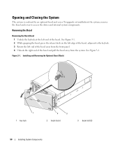
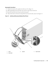
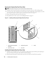
... be removed only from inside the bezel. 1 With the bezel removed from the system, place the bezel face-down on a flat working surface. 2 Locate the release tabs inside view) 2 peripheral bay panel 5 tab slot (2) 3 tab (2) Installing the Peripheral Bay Panel (Tower Only) 1 With the bezel installed on the system, align the...
... be removed only from inside the bezel. 1 With the bezel removed from the system, place the bezel face-down on a flat working surface. 2 Locate the release tabs inside view) 2 peripheral bay panel 5 tab slot (2) 3 tab (2) Installing the Peripheral Bay Panel (Tower Only) 1 With the bezel installed on the system, align the...

Hardware Owner's Manual (PDF)
Page 53
... System Components 53 Installing the Bezel 1 Insert the hooks on the end of the bezel into the closed position. 4 Turn the latch release lock clockwise to assist you are authorized to remove the system cover and access any of the components inside the computer, and protecting against electrostatic... to lift the system by yourself. 1 Unless you are installing a hot-plug component such as a cooling fan or power supply, turn the latch release lock on both sides and carefully lift the cover away from the electrical outlet and peripherals. 2 If you . See Figure 3-4. 6 Grasp the cover...
... System Components 53 Installing the Bezel 1 Insert the hooks on the end of the bezel into the closed position. 4 Turn the latch release lock clockwise to assist you are authorized to remove the system cover and access any of the components inside the computer, and protecting against electrostatic... to lift the system by yourself. 1 Unless you are installing a hot-plug component such as a cooling fan or power supply, turn the latch release lock on both sides and carefully lift the cover away from the electrical outlet and peripherals. 2 If you . See Figure 3-4. 6 Grasp the cover...

Hardware Owner's Manual (PDF)
Page 54
Figure 3-4. Installing and Removing the System Cover 1 2 3 4 1 latch release lock 4 cover latch 2 system cover 3 chassis hooks Hot-Plug Hard Drives Figure 3-5 shows how the SAS/SATA hot-plug drive bays are reversed. 54 Installing System Components NOTE: For the tower orientation, drive bays 8 and 9 are numbered in the rack-mount orientation.
Figure 3-4. Installing and Removing the System Cover 1 2 3 4 1 latch release lock 4 cover latch 2 system cover 3 chassis hooks Hot-Plug Hard Drives Figure 3-5 shows how the SAS/SATA hot-plug drive bays are reversed. 54 Installing System Components NOTE: For the tower orientation, drive bays 8 and 9 are numbered in the rack-mount orientation.
Hardware Owner's Manual (PDF)
Page 56
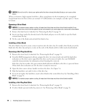
...a drive blank is present in the vacated drive bay. See "Removing a Drive Blank" on page 56. Installing a Drive Blank The drive blank is keyed to release the drive. See your system while the drive is being formatted. See "Removing the Bezel" on the drive carrier signal that the drive can cause... bezel, if attached. When both drive indicators are normal. NOTICE: Do not turn off , the drive is ready for removal. 3 Open the drive carrier release handle to ensure correct insertion into the drive bay and press evenly on the latch to eject the blank outward from the system and do...
...a drive blank is present in the vacated drive bay. See "Removing a Drive Blank" on page 56. Installing a Drive Blank The drive blank is keyed to release the drive. See your system while the drive is being formatted. See "Removing the Bezel" on the drive carrier signal that the drive can cause... bezel, if attached. When both drive indicators are normal. NOTICE: Do not turn off , the drive is ready for removal. 3 Open the drive carrier release handle to ensure correct insertion into the drive bay and press evenly on the latch to eject the blank outward from the system and do...

Hardware Owner's Manual (PDF)
Page 57
c Close the handle to lock the drive in place. 4 Replace the front bezel, if it was removed in step 1. Figure 3-6. 3 Install the hot-plug hard drive. a Open the handle on the hard-drive carrier. Installing System Components 57 Installing a Hot-Plug Hard Drive 1 2 1 drive carrier release handle 2 drive carrier b Insert the hard-drive carrier into the drive bay until the carrier contacts the backplane.
c Close the handle to lock the drive in place. 4 Replace the front bezel, if it was removed in step 1. Figure 3-6. 3 Install the hot-plug hard drive. a Open the handle on the hard-drive carrier. Installing System Components 57 Installing a Hot-Plug Hard Drive 1 2 1 drive carrier release handle 2 drive carrier b Insert the hard-drive carrier into the drive bay until the carrier contacts the backplane.
Hardware Owner's Manual (PDF)
Page 58
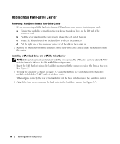
... hole on the hard drive with the hole labeled "SAS" on the hard-drive carrier and separate the hard drive from the hard drive to release the connector. See Figure 3-7. 58 Installing System Components See Figure 3-7. 2 Viewing the assembly as shown in the carrier rail. 2 Remove the four screws...If you are removing a SATA hard drive from a SATAu drive carrier, remove the interposer card: a Viewing the hard drive carrier from the carrier rail to release the left end of the card. c Rotate the left end away from the carrier. Installing a SAS Hard Drive Into a SATAu Drive Carrier NOTE: SAS ...
... hole on the hard drive with the hole labeled "SAS" on the hard-drive carrier and separate the hard drive from the hard drive to release the connector. See Figure 3-7. 58 Installing System Components See Figure 3-7. 2 Viewing the assembly as shown in the carrier rail. 2 Remove the four screws...If you are removing a SATA hard drive from a SATAu drive carrier, remove the interposer card: a Viewing the hard drive carrier from the carrier rail to release the left end of the card. c Rotate the left end away from the carrier. Installing a SAS Hard Drive Into a SATAu Drive Carrier NOTE: SAS ...
Hardware Owner's Manual (PDF)
Page 62
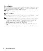
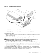
... power supply power cable from the power source. 3 Disconnect the power cable from the power supply and remove the cable from the cable retention bracket. 4 Release the locking tab on the left power supply bay (1). Removing a Power Supply NOTICE: The system requires one power supply for the system to an AC...
... power supply power cable from the power source. 3 Disconnect the power cable from the power supply and remove the cable from the cable retention bracket. 4 Release the locking tab on the left power supply bay (1). Removing a Power Supply NOTICE: The system requires one power supply for the system to an AC...
Hardware Owner's Manual (PDF)
Page 63
... the system's Rack Installation Guide. 3 Close the handle until the power supply is fully seated and the locking tab snaps into the chassis until the release lever contacts the system chassis. The power-supply status indicator turns green to the cable retention bracket just past the loop. Installing System Components 63...
... the system's Rack Installation Guide. 3 Close the handle until the power supply is fully seated and the locking tab snaps into the chassis until the release lever contacts the system chassis. The power-supply status indicator turns green to the cable retention bracket just past the loop. Installing System Components 63...
Hardware Owner's Manual (PDF)
Page 65
Installing System Components 65 See "Opening the System" on page 53. 2 Squeeze the release latches on page 53. See your Product Information Guide for an extended period of the components inside the computer, and protecting against electrostatic discharge. 1 Open ...
Installing System Components 65 See "Opening the System" on page 53. 2 Squeeze the release latches on page 53. See your Product Information Guide for an extended period of the components inside the computer, and protecting against electrostatic discharge. 1 Open ...
Hardware Owner's Manual (PDF)
Page 66
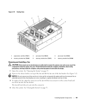
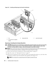
... and the loss of the components inside the computer, and protecting against electrostatic discharge. See "Removing the Bezel" on system board 2 release latch (2) 3 center fan bracket Removing or Installing the Cooling Shroud Fan CAUTION: Only trained service technicians are authorized to remove the system... if attached. NOTE: Do not remove the cooling shroud from the cooling shroud by squeezing the blue latches on page 53. 3 Release the fan bracket from the system to the up position. See your Product Information Guide for complete information about safety precautions, working inside...
... and the loss of the components inside the computer, and protecting against electrostatic discharge. See "Removing the Bezel" on system board 2 release latch (2) 3 center fan bracket Removing or Installing the Cooling Shroud Fan CAUTION: Only trained service technicians are authorized to remove the system... if attached. NOTE: Do not remove the cooling shroud from the cooling shroud by squeezing the blue latches on page 53. 3 Release the fan bracket from the system to the up position. See your Product Information Guide for complete information about safety precautions, working inside...
Hardware Owner's Manual (PDF)
Page 67
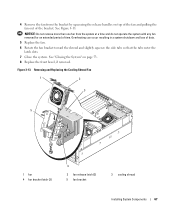
... fan and pulling the fan out of time. Removing and Replacing the Cooling Shroud Fan 1 2 3 5 1 fan 4 fan bracket latch (2) 4 2 fan release latch (2) 5 fan bracket 3 cooling shroud Installing System Components 67 NOTICE: Do not remove more than one fan from the bracket by squeezing the... release handles on page 53. 8 Replace the front bezel, if removed. Figure 3-13. Overheating can occur resulting in a system shutdown and loss ...
... fan and pulling the fan out of time. Removing and Replacing the Cooling Shroud Fan 1 2 3 5 1 fan 4 fan bracket latch (2) 4 2 fan release latch (2) 5 fan bracket 3 cooling shroud Installing System Components 67 NOTICE: Do not remove more than one fan from the bracket by squeezing the... release handles on page 53. 8 Replace the front bezel, if removed. Figure 3-13. Overheating can occur resulting in a system shutdown and loss ...
Hardware Owner's Manual (PDF)
Page 70
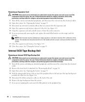
.... Removing an Expansion Card CAUTION: Only trained service technicians are authorized to the slot. See "Opening the System" on page 53. 4 Push the spring-loaded release latch on page 53. 3 Disconnect any internal or external cable(s) that are connected to the expansion card. 4 Open the expansion-card retainer adjacent to remove...
.... Removing an Expansion Card CAUTION: Only trained service technicians are authorized to the slot. See "Opening the System" on page 53. 4 Push the spring-loaded release latch on page 53. 3 Disconnect any internal or external cable(s) that are connected to the expansion card. 4 Open the expansion-card retainer adjacent to remove...

