Installing a SATA Optical Drive
Page 9
... your Hardware Owner's Manual. 11 Reconnect the system to the CD/TBU connector on the system and attached peripherals. For a PowerEdge 2900 system, connect to power and turn on the system backplane. See "Replacing the Center Fan Bracket" in the optical drive kit and connect one end to the optical drive and...
... your Hardware Owner's Manual. 11 Reconnect the system to the CD/TBU connector on the system and attached peripherals. For a PowerEdge 2900 system, connect to power and turn on the system backplane. See "Replacing the Center Fan Bracket" in the optical drive kit and connect one end to the optical drive and...

Installing a SATA Optical Drive
Page 10
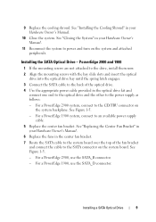
Figure 1-5. See "Closing the System" in a PowerEdge 2900 or 1900 3 2 4 5 1 1 optical drive 3 SATA data cable 5 SATA power connector on SAS backplane (PowerEdge 2900 only) 2 SATA power cable 4 SATA connector on the system and attached peripherals. 10 Installing a SATA Optical Drive SATA Cable Routing in your Hardware Owner's Manual. 10 Reconnect the system to power and turn on system board 8 Reconnect the cables to the SAS controller daughter card. 9 Close the system.
Figure 1-5. See "Closing the System" in a PowerEdge 2900 or 1900 3 2 4 5 1 1 optical drive 3 SATA data cable 5 SATA power connector on SAS backplane (PowerEdge 2900 only) 2 SATA power cable 4 SATA connector on the system and attached peripherals. 10 Installing a SATA Optical Drive SATA Cable Routing in your Hardware Owner's Manual. 10 Reconnect the system to power and turn on system board 8 Reconnect the cables to the SAS controller daughter card. 9 Close the system.

Information Update
Page 4
3.5-Inch Chassis Update 13 Front Features and Indicators 13 Mixed SAS/SATA Hard Drive Configuration (3.5-Inch Drives Only 15 Removing a 3.5-Inch Drive Blank 15 Installing a 3.5-Inch Drive Blank 15 Removing the SAS/SATA Backplane Board . . . . 16 Installing the SAS Backplane Board 18 SAS/SATA Backplane Board Connectors . . . . . 19 4 Contents
3.5-Inch Chassis Update 13 Front Features and Indicators 13 Mixed SAS/SATA Hard Drive Configuration (3.5-Inch Drives Only 15 Removing a 3.5-Inch Drive Blank 15 Installing a 3.5-Inch Drive Blank 15 Removing the SAS/SATA Backplane Board . . . . 16 Installing the SAS Backplane Board 18 SAS/SATA Backplane Board Connectors . . . . . 19 4 Contents

Information Update
Page 16
See Figure 1-3. NOTE: If you remove from which bay. Removing the SAS/SATA Backplane Board WARNING: Only trained service technicians are authorized to record which hard drive you choose to remove the hard drives, be sure to remove the ...
See Figure 1-3. NOTE: If you remove from which bay. Removing the SAS/SATA Backplane Board WARNING: Only trained service technicians are authorized to record which hard drive you choose to remove the hard drives, be sure to remove the ...

Information Update
Page 17
... Removal 1 2 3 1 drive carrier 3 SAS-backplane board release pin 2 SAS backplane board 4 If present, disconnect the optical drive power cable from the backplane connectors. See Figure 1-4 for the location of the SAS cable connectors. 6 If an optical drive is installed, disconnect the ...data cable from the back of the optical drive power connector. 5 Disconnect the SAS cable(s) from the SAS/SATA backplane board. See "Removing a SAS Controller Daughter Card" in your Hardware Owner's Manual. See Figure 1-4 for the location of the optical drive. 7...
... Removal 1 2 3 1 drive carrier 3 SAS-backplane board release pin 2 SAS backplane board 4 If present, disconnect the optical drive power cable from the backplane connectors. See Figure 1-4 for the location of the SAS cable connectors. 6 If an optical drive is installed, disconnect the ...data cable from the back of the optical drive power connector. 5 Disconnect the SAS cable(s) from the SAS/SATA backplane board. See "Removing a SAS Controller Daughter Card" in your Hardware Owner's Manual. See Figure 1-4 for the location of the optical drive. 7...

Information Update
Page 18
...your Product Information Guide for complete information about safety precautions, working inside the system. 8 Remove the SAS backplane board: a Pull the SAS-backplane board release pin. Installing the SAS Backplane Board WARNING: Only trained service technicians are fully inserted into place. 4 Reinstall the SAS controller daughter card...and access any of the system until it stops, then release the release pin and ensure that the securing tabs on the backplane board. See "Installing the Optical Drive" in your Hardware Owner's Manual. 8 Close the system. See Figure 1-3. b While pulling the...
...your Product Information Guide for complete information about safety precautions, working inside the system. 8 Remove the SAS backplane board: a Pull the SAS-backplane board release pin. Installing the SAS Backplane Board WARNING: Only trained service technicians are fully inserted into place. 4 Reinstall the SAS controller daughter card...and access any of the system until it stops, then release the release pin and ensure that the securing tabs on the backplane board. See "Installing the Optical Drive" in your Hardware Owner's Manual. 8 Close the system. See Figure 1-3. b While pulling the...

Information Update
Page 19
SAS/SATA Backplane Board Connectors Figure 1-4 shows the location of the connectors on the SAS/SATA backplane board. Figure 1-4. SAS Backplane Board Components: 3.5-inch x4 Option 1 2 3 10 9 8 front 7 6 4 5 back 1 primary SAS (SAS_A) 3 secondary SAS (SAS_B) 5 backplane power (BP_PWR) 7 drive 3 (SASDRV3) 9 drive 1 (SASDRV1) 2 optical drive power (CD_PWR) 4 drive 5 (SASDRV5) 6 drive 4 (SASDRV4) 8 drive 2 (SASDRV2) 10 drive 0 (SASDRV0) Information Update 19
SAS/SATA Backplane Board Connectors Figure 1-4 shows the location of the connectors on the SAS/SATA backplane board. Figure 1-4. SAS Backplane Board Components: 3.5-inch x4 Option 1 2 3 10 9 8 front 7 6 4 5 back 1 primary SAS (SAS_A) 3 secondary SAS (SAS_B) 5 backplane power (BP_PWR) 7 drive 3 (SASDRV3) 9 drive 1 (SASDRV1) 2 optical drive power (CD_PWR) 4 drive 5 (SASDRV5) 6 drive 4 (SASDRV4) 8 drive 2 (SASDRV2) 10 drive 0 (SASDRV0) Information Update 19

Hardware Owner's Manual
Page 6
... Center Riser Board 104 Sideplane Board 105 Removing the Sideplane Board 105 Installing the Sideplane Board 107 SAS/SATA Backplane Board 107 Removing the SAS/SATA Backplane Board 107 Installing the SAS/SATA Backplane Board 108 Control Panel Assembly (Service-only Procedure 109 Removing the Control Panel Assembly 109 Installing the Control Panel...
... Center Riser Board 104 Sideplane Board 105 Removing the Sideplane Board 105 Installing the Sideplane Board 107 SAS/SATA Backplane Board 107 Removing the SAS/SATA Backplane Board 107 Installing the SAS/SATA Backplane Board 108 Control Panel Assembly (Service-only Procedure 109 Removing the Control Panel Assembly 109 Installing the Control Panel...

Hardware Owner's Manual
Page 8
... Testing 136 Selecting Diagnostics Options 137 Viewing Information and Results 137 6 Jumpers and Connectors 139 System Board Jumpers 139 System Board Connectors 141 SAS/SATA Backplane Board Connectors 143 Sideplane Board Connectors 144 Expansion-Card Riser-Board Components and PCIe Buses 144 Disabling a Forgotten Password 145 7 Getting Help 147 Technical Assistance...
... Testing 136 Selecting Diagnostics Options 137 Viewing Information and Results 137 6 Jumpers and Connectors 139 System Board Jumpers 139 System Board Connectors 141 SAS/SATA Backplane Board Connectors 143 Sideplane Board Connectors 144 Expansion-Card Riser-Board Components and PCIe Buses 144 Disabling a Forgotten Password 145 7 Getting Help 147 Technical Assistance...

Hardware Owner's Manual
Page 51
... • Optical, diskette, and tape drives • System memory • Processors • System battery • Expansion-card riser boards • Sideplane board • SAS/SATA Backplane board • Control panel assembly • System board Recommended Tools You may need the following items to perform the procedures in this section: • Key...
... • Optical, diskette, and tape drives • System memory • Processors • System battery • Expansion-card riser boards • Sideplane board • SAS/SATA Backplane board • Control panel assembly • System board Recommended Tools You may need the following items to perform the procedures in this section: • Key...

Hardware Owner's Manual
Page 52
... for optional diskette 15 drive and/or tape drive sideplane expansion-card cage and left riser (PCIe slots 2 and 3) memory modules (up to 8) SAS/SATA backplane SAS or SATA hard drives (up to 8) 52 Installing System Components Inside the System 6 2 1 5 4 3 7 8 16 9 10 11 15 12 14 13 1 RAID battery (optional) 2 4 power...
... for optional diskette 15 drive and/or tape drive sideplane expansion-card cage and left riser (PCIe slots 2 and 3) memory modules (up to 8) SAS/SATA backplane SAS or SATA hard drives (up to 8) 52 Installing System Components Inside the System 6 2 1 5 4 3 7 8 16 9 10 11 15 12 14 13 1 RAID battery (optional) 2 4 power...

Hardware Owner's Manual
Page 53
... 2.5-inch SAS or eight 2.5-inch SATA hard drives. For more information, see "System Board Jumpers" on the front panel and accessible through the SAS/SATA backplane board. A control panel LCD located on page 139. For more information, see "Hard Drives" on page 56 and "SAS Controller Daughter Card" on the system...
... 2.5-inch SAS or eight 2.5-inch SATA hard drives. For more information, see "System Board Jumpers" on the front panel and accessible through the SAS/SATA backplane board. A control panel LCD located on page 139. For more information, see "Hard Drives" on page 56 and "SAS Controller Daughter Card" on the system...

Hardware Owner's Manual
Page 56
... the cover. Removing the Cover 1 2 3 1 latch 2 latch release lock 3 alignment J hooks Hard Drives This subsection describes how to the system board through the SAS/SATA backplane board. Closing the System 1 Lift up to eight 2.5-inch hard drives.
... the cover. Removing the Cover 1 2 3 1 latch 2 latch release lock 3 alignment J hooks Hard Drives This subsection describes how to the system board through the SAS/SATA backplane board. Closing the System 1 Lift up to eight 2.5-inch hard drives.

Hardware Owner's Manual
Page 57
... drive is free of hours to lock the blank in step 1. Remove the drive blank as you must replace the carrier with the SAS/SATA backplane board. Mixed drive configurations are off or reboot your SAS RAID controller documentation for removal. 3 Open the drive carrier release handle to partition and format...
... drive is free of hours to lock the blank in step 1. Remove the drive blank as you must replace the carrier with the SAS/SATA backplane board. Mixed drive configurations are off or reboot your SAS RAID controller documentation for removal. 3 Open the drive carrier release handle to partition and format...

Hardware Owner's Manual
Page 59
Installing a Hard Drive Into a Drive Carrier 1 Insert the hard drive into the drive bay until the carrier contacts the backplane. b Insert the hard-drive carrier into the hard-drive carrier with the rear set of holes on the hard drive carrier. See Figure 3-6. See Figure 3-6. 2 ...
Installing a Hard Drive Into a Drive Carrier 1 Insert the hard drive into the drive bay until the carrier contacts the backplane. b Insert the hard-drive carrier into the hard-drive carrier with the rear set of holes on the hard drive carrier. See Figure 3-6. See Figure 3-6. 2 ...

Hardware Owner's Manual
Page 66
... only) SAS controller daughter card socket SAS connector(s) (1 or 2) 5 Attach the interface cable(s) to the SAS controller daughter card and to the backplane. • For a non-RAID SAS controller (with dual connectors), attach the first interface cable to connector 0 on the SAS RAID controller and to... the SAS_A connector on the backplane. See Figure 3-10. • For a SAS RAID controller (with a single connector), attach one end of the interface cable to connector 0...
... only) SAS controller daughter card socket SAS connector(s) (1 or 2) 5 Attach the interface cable(s) to the SAS controller daughter card and to the backplane. • For a non-RAID SAS controller (with dual connectors), attach the first interface cable to connector 0 on the SAS RAID controller and to... the SAS_A connector on the backplane. See Figure 3-10. • For a SAS RAID controller (with a single connector), attach one end of the interface cable to connector 0...

Hardware Owner's Manual
Page 67
SAS Controller Daughter Card Cabling 2 1 3 4 1 SAS controller daughter card 2 SAS controller 0 4 SAS/SATA backplane 3 backplane connector A (SAS_A) Installing System Components 67 Figure 3-10. See "Installing a RAID Battery" on page 69. 6 If you are installing a SAS RAID controller, install the RAID battery.
SAS Controller Daughter Card Cabling 2 1 3 4 1 SAS controller daughter card 2 SAS controller 0 4 SAS/SATA backplane 3 backplane connector A (SAS_A) Installing System Components 67 Figure 3-10. See "Installing a RAID Battery" on page 69. 6 If you are installing a SAS RAID controller, install the RAID battery.

Hardware Owner's Manual
Page 68
See Figure 3-9. 68 Installing System Components Figure 3-11. SAS RAID Controller Daughter Card Cabling 3 2 1 4 5 6 1 SAS RAID controller daughter 2 card 4 backplane connector A 5 (SAS_A) SAS controller 0 backplane connector B (SAS_B) 3 SAS controller 1 6 SAS/SATA backplane Removing a SAS Controller Daughter Card 1 Disconnect any battery connectors if applicable. 2 Disconnect any SAS cables from the card. 3 Gently press down on...
See Figure 3-9. 68 Installing System Components Figure 3-11. SAS RAID Controller Daughter Card Cabling 3 2 1 4 5 6 1 SAS RAID controller daughter 2 card 4 backplane connector A 5 (SAS_A) SAS controller 0 backplane connector B (SAS_B) 3 SAS controller 1 6 SAS/SATA backplane Removing a SAS Controller Daughter Card 1 Disconnect any battery connectors if applicable. 2 Disconnect any SAS cables from the card. 3 Gently press down on...

Hardware Owner's Manual
Page 89
... See Figure 6-3 for the connector locations on the system board. 10 Connect the tape drive power cable to either the SATA_A or SATA_B on the backplane.
... See Figure 6-3 for the connector locations on the system board. 10 Connect the tape drive power cable to either the SATA_A or SATA_B on the backplane.

Hardware Owner's Manual
Page 107
...disconnect the system from the electrical outlet. 2 Insert the sideplane board into the system board connector. SAS/SATA Backplane Board Removing the SAS/SATA Backplane Board CAUTION: Only trained service technicians are authorized to the sideplane board. 4 If applicable, replace the storage ...any of the system. See "Closing the System" on page 55. 3 Disconnect the optical drive power cable from the SAS/SATA backplane board. See your Product Information Guide for complete information about safety precautions, working inside the system. NOTE: To properly reinstall the hard...
...disconnect the system from the electrical outlet. 2 Insert the sideplane board into the system board connector. SAS/SATA Backplane Board Removing the SAS/SATA Backplane Board CAUTION: Only trained service technicians are authorized to the sideplane board. 4 If applicable, replace the storage ...any of the system. See "Closing the System" on page 55. 3 Disconnect the optical drive power cable from the SAS/SATA backplane board. See your Product Information Guide for complete information about safety precautions, working inside the system. NOTE: To properly reinstall the hard...


