
Service Manual
Page 3
Contents Chapter 1 System Overview 1-1 System Features 1-1 System Memory 1-7 Advanced Expansion Subsystem 1-7 Integrated Server Management 1-8 Video Controller 1-8 Integrated SCSI Controllers 1-8 SCSI Hard-Disk Drives 1-8 SCSI Configuration Guidelines 1-9 SCSI ID Numbers 1-9 Device Termination 1-9 SCSI Cable 1-10 System Unit 1-10 System ...
Contents Chapter 1 System Overview 1-1 System Features 1-1 System Memory 1-7 Advanced Expansion Subsystem 1-7 Integrated Server Management 1-8 Video Controller 1-8 Integrated SCSI Controllers 1-8 SCSI Hard-Disk Drives 1-8 SCSI Configuration Guidelines 1-9 SCSI ID Numbers 1-9 Device Termination 1-9 SCSI Cable 1-10 System Unit 1-10 System ...

Service Manual
Page 9
Chapter 1 System Overview The Dell® PowerEdge® 6100 system covered in this manual is a high-speed, scalable, upgradable server system that connect to the system board. SIMMs and microprocessors are located on the system board • ...in to integrate your servers. These buses are freestanding or can have been designed for information about Dell-supported microprocessor upgrades. PowerEdge 6100 systems incorporate the high-performance PCI local bus as well as the EISA expansion bus. The microprocessor's internal speed for the Dell PowerEdge 6100/200 system is installed...
Chapter 1 System Overview The Dell® PowerEdge® 6100 system covered in this manual is a high-speed, scalable, upgradable server system that connect to the system board. SIMMs and microprocessors are located on the system board • ...in to integrate your servers. These buses are freestanding or can have been designed for information about Dell-supported microprocessor upgrades. PowerEdge 6100 systems incorporate the high-performance PCI local bus as well as the EISA expansion bus. The microprocessor's internal speed for the Dell PowerEdge 6100/200 system is installed...

Service Manual
Page 10
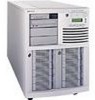
... assume that monitors critical system volt- back of computer left side right side front of system features, see the "Dell PowerEdge 4100 and 6100 Systems Rack Kit Installation Guide" (P/N 40722). ages and temperatures, as well as the operation of these features are ...server management circuitry that the location or direction relative to prevent accidental system interruptions All of the system cooling fans • CD-ROM drive standard in an externally accessible drive bay • Recessed power and reset buttons to the system is as shown in Figure 1-1. 1-2 Dell PowerEdge 6100...
... assume that monitors critical system volt- back of computer left side right side front of system features, see the "Dell PowerEdge 4100 and 6100 Systems Rack Kit Installation Guide" (P/N 40722). ages and temperatures, as well as the operation of these features are ...server management circuitry that the location or direction relative to prevent accidental system interruptions All of the system cooling fans • CD-ROM drive standard in an externally accessible drive bay • Recessed power and reset buttons to the system is as shown in Figure 1-1. 1-2 Dell PowerEdge 6100...

Service Manual
Page 16
...are located on the system board (see Figure 1-14). For detailed information about installing externally accessible drives, see Figure 1-3). For 1-8 Dell PowerEdge 6100/200 System Service Manual Video Controller The video subsystem (Cirrus Logic CL5424) is connected to external SCSI devices. The expansion-card connectors... and six PCI expansion-card connectors. These bays can contain up to 1.6-inch-high SCSI hard-disk drives. The integrated server management circuitry works in the SCSI hard-disk drive bays. The ten expansion-card slots consist of DRAM memory (the video...
...are located on the system board (see Figure 1-14). For detailed information about installing externally accessible drives, see Figure 1-3). For 1-8 Dell PowerEdge 6100/200 System Service Manual Video Controller The video subsystem (Cirrus Logic CL5424) is connected to external SCSI devices. The expansion-card connectors... and six PCI expansion-card connectors. These bays can contain up to 1.6-inch-high SCSI hard-disk drives. The integrated server management circuitry works in the SCSI hard-disk drive bays. The ten expansion-card slots consist of DRAM memory (the video...

Service Manual
Page 29
... probe (ITP). jumpered unjumpered SCSI Backplane Board Ultra/Wide SCSI cable connector (SCSI) power input connector (POWER) 6 SCA-2 compatible SCSI connectors (SLOTnID=n, on other side) server-management bus connector (SERVER MANAGEMENT) control (front) panel connector (CONTROL PANEL) Figure 1-17.
... probe (ITP). jumpered unjumpered SCSI Backplane Board Ultra/Wide SCSI cable connector (SCSI) power input connector (POWER) 6 SCA-2 compatible SCSI connectors (SLOTnID=n, on other side) server-management bus connector (SERVER MANAGEMENT) control (front) panel connector (CONTROL PANEL) Figure 1-17.

Service Manual
Page 30
SCSI Backplane Board Connectors Connector Description CONTROL PANEL Control panel connector POWER Power input connector SCSI Ultra/Wide SCSI cable connector SERVER MANAGEMENT Server-management bus connector SLOTnID=n SCA-2 compatible SCSI connectors Interrupt Assignments Table 1-5. Table 1-4. Interrupt Assignments IRQ Line Used/Available IRQ0 Used by the system timer IRQ1... IRQ13 Used by the math coprocessor to indicate coprocessor error IRQ14 Available for use by expansion card IRQ15 Available for use by expansion card 1-22 Dell PowerEdge 6100/200 System Service Manual
SCSI Backplane Board Connectors Connector Description CONTROL PANEL Control panel connector POWER Power input connector SCSI Ultra/Wide SCSI cable connector SERVER MANAGEMENT Server-management bus connector SLOTnID=n SCA-2 compatible SCSI connectors Interrupt Assignments Table 1-5. Table 1-4. Interrupt Assignments IRQ Line Used/Available IRQ0 Used by the system timer IRQ1... IRQ13 Used by the math coprocessor to indicate coprocessor error IRQ14 Available for use by expansion card IRQ15 Available for use by expansion card 1-22 Dell PowerEdge 6100/200 System Service Manual

Service Manual
Page 34
one 270-pin connector for the memory module PROCESSOR MODULE #n two 270-pin connectors for the server manage- one 68-pin connector SERVER MANAGEMENT one 14-pin connector SCSI (ultra-wide SCSI cable) . . . . . ment module MEMORY MODULE . . . Technical Specifications (continued) System Board Connectors (continued) PARALLEL (bidirectional one 25-... connectors SCSI Backplane Connectors CONTROL PANEL one 30-pin connector POWER one 16-pin connector SLOTnID=n (SCSI hard-disk drive six 80-pin connectors 1-26 Dell PowerEdge 6100/200 System Service Manual Table 1-7.
one 270-pin connector for the memory module PROCESSOR MODULE #n two 270-pin connectors for the server manage- one 68-pin connector SERVER MANAGEMENT one 14-pin connector SCSI (ultra-wide SCSI cable) . . . . . ment module MEMORY MODULE . . . Technical Specifications (continued) System Board Connectors (continued) PARALLEL (bidirectional one 25-... connectors SCSI Backplane Connectors CONTROL PANEL one 30-pin connector POWER one 16-pin connector SLOTnID=n (SCSI hard-disk drive six 80-pin connectors 1-26 Dell PowerEdge 6100/200 System Service Manual Table 1-7.

Service Manual
Page 39
... and is off within approximately 10 seconds after the boot routine starts? If a system error message is set to or from the drives. Insert the Dell Server Assistant CD into the CD-ROM drive. Check the power supply fans. No. Do these indicators fails to light up during the boot routine, troubleshoot...
... and is off within approximately 10 seconds after the boot routine starts? If a system error message is set to or from the drives. Insert the Dell Server Assistant CD into the CD-ROM drive. Check the power supply fans. No. Do these indicators fails to light up during the boot routine, troubleshoot...

Service Manual
Page 40
5. Yes. See "Running the System Diagnostics" found later in Chapter 4. 2-4 Dell PowerEdge 6100/200 System Service Manual Proceed to avoid electrical shock. 2. Verify that the user has saved all open files and exited all the AC power cables ... their sockets, press firmly on the top of a problem, such as described in "Computer Covers" in the inspection procedure. Observe the monitor screen for the Dell Server Assistant main menu. A simple visual inspection of a computer's interior hardware can get extremely hot. When you perform the visual inspection, refer to "System Features" in...
5. Yes. See "Running the System Diagnostics" found later in Chapter 4. 2-4 Dell PowerEdge 6100/200 System Service Manual Proceed to avoid electrical shock. 2. Verify that the user has saved all open files and exited all the AC power cables ... their sockets, press firmly on the top of a problem, such as described in "Computer Covers" in the inspection procedure. Observe the monitor screen for the Dell Server Assistant main menu. A simple visual inspection of a computer's interior hardware can get extremely hot. When you perform the visual inspection, refer to "System Features" in...

Service Manual
Page 41
...to the next section, "Eliminating Resource Conflicts," and to appear on the Dell Server Assistant CD) contains tests that all jumper and switch settings are set correctly. Restarting the computer causes the Dell Server Assistant logo screen to "Getting Help" found later in this chapter. Reinstall... load the diagnostics program. Use the keyboard to choose Run System Utilities, and then select Run System Diagnostics to the Dell Server Assistant main menu (without mouse support). Eliminating Resource Conflicts Devices within the computer may be installed at all cable connectors...
...to the next section, "Eliminating Resource Conflicts," and to appear on the Dell Server Assistant CD) contains tests that all jumper and switch settings are set correctly. Restarting the computer causes the Dell Server Assistant logo screen to "Getting Help" found later in this chapter. Reinstall... load the diagnostics program. Use the keyboard to choose Run System Utilities, and then select Run System Diagnostics to the Dell Server Assistant main menu (without mouse support). Eliminating Resource Conflicts Devices within the computer may be installed at all cable connectors...

Service Manual
Page 42
Tests a particular area or subsystem NOTE: Before running the diagnostics program, make a blank, formatted diskette to the Dell Server Assistant menu: • Run All Tests - appears, allowing you to choose the following options or exit to MS-DOS...Tests - See Chapter 5, "Running the System Diagnostics," in the Installation and Troubleshooting Guide. 2-6 Dell PowerEdge 6100/200 System Service Manual Runs selected tests from all tests for a thorough check of the problem, call Dell for technical assistance. For instructions, see Chapter 11, "Getting Help," in the Installation and ...
Tests a particular area or subsystem NOTE: Before running the diagnostics program, make a blank, formatted diskette to the Dell Server Assistant menu: • Run All Tests - appears, allowing you to choose the following options or exit to MS-DOS...Tests - See Chapter 5, "Running the System Diagnostics," in the Installation and Troubleshooting Guide. 2-6 Dell PowerEdge 6100/200 System Service Manual Runs selected tests from all tests for a thorough check of the problem, call Dell for technical assistance. For instructions, see Chapter 11, "Getting Help," in the Installation and ...

Service Manual
Page 64
... (FAN1 and FAN2) server-management module connector (J3G1) fan connectors (FAN3 and FAN4) Ultra/Wide SCSI host adapter connector (SCSI A) Ultra/Wide SCSI host adapter connector (SCSI B) Figure 4-15. System Board Components The subsections that follow contain procedures for removing system board components. System Board Components 4-16 Dell PowerEdge 6100/200 System Service Manual...
... (FAN1 and FAN2) server-management module connector (J3G1) fan connectors (FAN3 and FAN4) Ultra/Wide SCSI host adapter connector (SCSI A) Ultra/Wide SCSI host adapter connector (SCSI B) Figure 4-15. System Board Components The subsections that follow contain procedures for removing system board components. System Board Components 4-16 Dell PowerEdge 6100/200 System Service Manual...

Service Manual
Page 94
... bays, 1-4, 1-5 connectors on SCSI backplane, 1-21 hard-disk drives, SCSI configurations, 1-8, 1-9 illustrated, 4-5 removal, 4-9 help, getting, 2-6 I initial procedures, 2-1 initialization error messages, 3-2 integrated features SCSI controllers, 1-8, 1-21 server management, 1-8 video controller, 1-8 internal visual inspection, 2-4 interrupt assignments list of, 1-22 ISA expansion cards, 1-7, 4-17 See also expansion cards 2 Dell PowerEdge 6100/200 System Service Manual
... bays, 1-4, 1-5 connectors on SCSI backplane, 1-21 hard-disk drives, SCSI configurations, 1-8, 1-9 illustrated, 4-5 removal, 4-9 help, getting, 2-6 I initial procedures, 2-1 initialization error messages, 3-2 integrated features SCSI controllers, 1-8, 1-21 server management, 1-8 video controller, 1-8 internal visual inspection, 2-4 interrupt assignments list of, 1-22 ISA expansion cards, 1-7, 4-17 See also expansion cards 2 Dell PowerEdge 6100/200 System Service Manual

Service Manual
Page 96
..., A-14 Floppy Options submenu, A-4 key functions, A-2 Main menu, A-3 menus, A-1 Peripheral Configuration submenu, A-7 4 Dell PowerEdge 6100/200 System Service Manual See hard-disk drives, SCSI SCSI ID numbers, 1-9 SERIAL connectors, 4-16 serial port connectors location on I/O panel, 1-6 location on system board, 4-16 server-management module connector, 4-16 SIMMs memory module illustrated, 1-7, 4-20 module connector on...
..., A-14 Floppy Options submenu, A-4 key functions, A-2 Main menu, A-3 menus, A-1 Peripheral Configuration submenu, A-7 4 Dell PowerEdge 6100/200 System Service Manual See hard-disk drives, SCSI SCSI ID numbers, 1-9 SERIAL connectors, 4-16 serial port connectors location on I/O panel, 1-6 location on system board, 4-16 server-management module connector, 4-16 SIMMs memory module illustrated, 1-7, 4-20 module connector on...


