
Glossary
Page 1
... a processor, memory, and a hard drive. BMC - BTU - A fast storage area that is located. Centimeter(s). 1 ACPI - asset tag - blade - A CD, diskette, or USB memory key that keeps a copy of data or instructions for interchange of a system. Common Information Model describes the ...management information utilized by an administrator, for the peripheral devices connected to start your system's hard drive(s) on the dictionary. Dell™ Glossary NOTE: For additional information on storage terminology, visit the Storage Networking Industry Association's website at www.snia.org...
... a processor, memory, and a hard drive. BMC - BTU - A fast storage area that is located. Centimeter(s). 1 ACPI - asset tag - blade - A CD, diskette, or USB memory key that keeps a copy of data or instructions for interchange of a system. Common Information Model describes the ...management information utilized by an administrator, for the peripheral devices connected to start your system's hard drive(s) on the dictionary. Dell™ Glossary NOTE: For additional information on storage terminology, visit the Storage Networking Industry Association's website at www.snia.org...
Dell M8428-k Getting Started Guide
Page 5
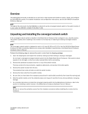
... to help experienced installers unpack, install, and configure the Dell M8428-k quickly. Open the shipping box and inspect the contents, making sure that is shipped to install the converged network switch into the Blade Blade Server Enclosure. For complete instructions to you have taken the...is intended as the converged network switch or the switch module. Perform the following steps to the section on top of the Dell M1000e Blade Server Enclosure for any obvious defects or shipping damage. 7. Remove the cardboard accessory tray from on installing a switch module in...
... to help experienced installers unpack, install, and configure the Dell M8428-k quickly. Open the shipping box and inspect the contents, making sure that is shipped to install the converged network switch into the Blade Blade Server Enclosure. For complete instructions to you have taken the...is intended as the converged network switch or the switch module. Perform the following steps to the section on top of the Dell M1000e Blade Server Enclosure for any obvious defects or shipping damage. 7. Remove the cardboard accessory tray from on installing a switch module in...

Dell M8428-k Getting Started Guide
Page 6
...and corresponding subnet mask and gateway address unless DHCP is only required if not changing the converged network switch IP address through the Blade Server Enclosure GUI or CLI management programs. • SFP transceivers and compatible fibre cables, as HyperTerminal) or a keyboard, ... FTP server for backing up the converged network switch configuration. • Access to these publications: • Blade Server Enclosure Hardware Owner's Manual • Blade Server Enclosure Configuration Guide 4 of 160 Dell M8428-k Getting Started Guide MHWKY Note that use twin-ax copper cables.
...and corresponding subnet mask and gateway address unless DHCP is only required if not changing the converged network switch IP address through the Blade Server Enclosure GUI or CLI management programs. • SFP transceivers and compatible fibre cables, as HyperTerminal) or a keyboard, ... FTP server for backing up the converged network switch configuration. • Access to these publications: • Blade Server Enclosure Hardware Owner's Manual • Blade Server Enclosure Configuration Guide 4 of 160 Dell M8428-k Getting Started Guide MHWKY Note that use twin-ax copper cables.

Dell M8428-k Getting Started Guide
Page 7
...'s Setup tab. 3. If the IP values are stored on the switch module. • Blade Server Enclosure CMC CLI. • Blade Server Enclosure CMC graphical user interface (GUI). • Dell M8428-k command line interface (CLI). ATTENTION Do not connect the switch module to fabric connections ...for switch module installed in bay C1. • Switch-6 for your Blade Server Enclosure CLI documentation. Establish a Telnet session to connect modify the converged network switch IP address through the CMC CLI. 1. Dell M8428-k Getting Started Guide MHWKY 5 of the converged network switch. ...
...'s Setup tab. 3. If the IP values are stored on the switch module. • Blade Server Enclosure CMC CLI. • Blade Server Enclosure CMC graphical user interface (GUI). • Dell M8428-k command line interface (CLI). ATTENTION Do not connect the switch module to fabric connections ...for switch module installed in bay C1. • Switch-6 for your Blade Server Enclosure CLI documentation. Establish a Telnet session to connect modify the converged network switch IP address through the CMC CLI. 1. Dell M8428-k Getting Started Guide MHWKY 5 of the converged network switch. ...

Dell M8428-k Getting Started Guide
Page 8
...and a Blade Server Enclosure management workstation used for your Blade Server Enclosure. 2. For instructions, refer to reset the module's IP address using the module's CLI. You will use its CLI commands to change the IP address on the workstation. 3. c. Using the Dell M8428-k ...), establish a terminal session to establish a terminal emulation session between the serial console port on the converged network switch and a Blade Server Enclosure management workstation that are running on the switch module using CLI commands and perform other configuration tasks. Click Start and ...
...and a Blade Server Enclosure management workstation used for your Blade Server Enclosure. 2. For instructions, refer to reset the module's IP address using the module's CLI. You will use its CLI commands to change the IP address on the workstation. 3. c. Using the Dell M8428-k ...), establish a terminal session to establish a terminal emulation session between the serial console port on the converged network switch and a Blade Server Enclosure management workstation that are running on the switch module using CLI commands and perform other configuration tasks. Click Start and ...
Dell M8428-k Getting Started Guide
Page 10
... shown: fcoeport no shut exit 7. Using the converged network switch CLI, you have successfully set the appropriate IP address of 160 Dell M8428-k Getting Started Guide MHWKY c. The management workstation must be on the commands. Be sure you can establish an Ethernet connection through...the transceiver correctly and insert it into a port until configuration is in NPIV or full fabric mode. Repeat steps 5-6 for any other blade port you can enter the ag --modeShow command to configure. 8. See the Converged Enhanced Ethernet Administrator's Guide for information about CEE CLI...
... shown: fcoeport no shut exit 7. Using the converged network switch CLI, you have successfully set the appropriate IP address of 160 Dell M8428-k Getting Started Guide MHWKY c. The management workstation must be on the commands. Be sure you can establish an Ethernet connection through...the transceiver correctly and insert it into a port until configuration is in NPIV or full fabric mode. Repeat steps 5-6 for any other blade port you can enter the ag --modeShow command to configure. 8. See the Converged Enhanced Ethernet Administrator's Guide for information about CEE CLI...

Intel Xeon Processor E7-2800/4800/8800 Product Family - Information Update
Page 3
... numeral "II" support Intel Xeon processor E7-2800/4800/8800 product family with the Roman numeral "II" on the system identification panel (PowerEdge R910 II and R810 II) or on the blade handle (PowerEdge M910 II). Identifying new Dell PowerEdge Systems With Roman Numeral II PowerEdge R910 II PowerEdge R810 II PowerEdge M910 II Information Update 3 See Figure 1.
... numeral "II" support Intel Xeon processor E7-2800/4800/8800 product family with the Roman numeral "II" on the system identification panel (PowerEdge R910 II and R810 II) or on the blade handle (PowerEdge M910 II). Identifying new Dell PowerEdge Systems With Roman Numeral II PowerEdge R910 II PowerEdge R810 II PowerEdge M910 II Information Update 3 See Figure 1.

Information Update
Page 5
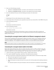
.../O module port mapping for a half-height blade with the quad-port mezzanine card. I/O Module Port Mapping (Quad-Port Mezzanine Cards) The following table, n denotes a variable value from 1 to 16. NOTE: For a detailed mapping of each PowerEdge system, see the document Quadport Capable Hardware For... the M1000e Modular Chassis on support.dell.com/manuals. In the following table illustrates the I /O Module B1 C1 C2 B2 A2 Port n Port...
.../O module port mapping for a half-height blade with the quad-port mezzanine card. I/O Module Port Mapping (Quad-Port Mezzanine Cards) The following table, n denotes a variable value from 1 to 16. NOTE: For a detailed mapping of each PowerEdge system, see the document Quadport Capable Hardware For... the M1000e Modular Chassis on support.dell.com/manuals. In the following table illustrates the I /O Module B1 C1 C2 B2 A2 Port n Port...

Information Update
Page 6
... from 1 to 8 • LOM1 and LOM2 are the LOM ports of blade n and LOM3 and LOM4 are the LOM ports of blade (n+8) NOTE: For a detailed mapping of each PowerEdge system, see the document Quadport Capable Hardware For the M1000e Modular Chassis on support.dell.com/manuals. Table 1-2. The following table illustrates the I /O Module A1...
... from 1 to 8 • LOM1 and LOM2 are the LOM ports of blade n and LOM3 and LOM4 are the LOM ports of blade (n+8) NOTE: For a detailed mapping of each PowerEdge system, see the document Quadport Capable Hardware For the M1000e Modular Chassis on support.dell.com/manuals. Table 1-2. The following table illustrates the I /O Module A1...

Information Update
Page 7
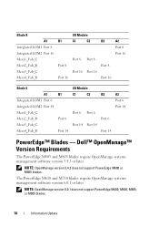
I/O Module Port Assignments-Full-Height Blades (continued) Blade n and Blade (n + 8) I/O Module A1 B1 C1 C2 B2 A2 Mezz_FAB_B_Blade n+8_Port1 Port (n+8) Mezz_FAB_B_Blade n+8_Port2 Port (n+8) Mezz_FAB_B_Blade n+8_Port3 Port (n+24) Mezz_FAB_B_Blade n+8_Port4 Port (n+24) Mezz_FAB_C_Blade n+8_Port1 Port (n+8) Mezz_FAB_C_Blade n+8_Port2 Port (n+8) Mezz_FAB_C_Blade n+8_Port3 Port (n+24) Mezz_FAB_C_Blade n+8_Port4 Port (n+24) Information Update 7 Table 1-2.
I/O Module Port Assignments-Full-Height Blades (continued) Blade n and Blade (n + 8) I/O Module A1 B1 C1 C2 B2 A2 Mezz_FAB_B_Blade n+8_Port1 Port (n+8) Mezz_FAB_B_Blade n+8_Port2 Port (n+8) Mezz_FAB_B_Blade n+8_Port3 Port (n+24) Mezz_FAB_B_Blade n+8_Port4 Port (n+24) Mezz_FAB_C_Blade n+8_Port1 Port (n+8) Mezz_FAB_C_Blade n+8_Port2 Port (n+8) Mezz_FAB_C_Blade n+8_Port3 Port (n+24) Mezz_FAB_C_Blade n+8_Port4 Port (n+24) Information Update 7 Table 1-2.

Information Update
Page 8
... that the mezzanine card ports are not supported on the IOM fabric. • N/A denotes that the fabric does not exist for Quad-Port Mezzanine Card PowerEdge Blade Fabric B1 Port 1 Port 3 and 2 and 4 M710 X X M905 X X M805 X X M605 X X M610 X X M600 X X Fabric C1 Port 1 and 2 X Port 3 ... X X X N/A N/A N/A Fabric C2 Port 1 and 2 X Port 3 and 4 N/A N/A N/A N/A N/A N/A 8 Information Update Configuration Matrix for the corresponding half-height blades. The following tables shows the compatibility of the PowerEdge blade systems with the quad-port mezzanine card. Table...
... that the mezzanine card ports are not supported on the IOM fabric. • N/A denotes that the fabric does not exist for Quad-Port Mezzanine Card PowerEdge Blade Fabric B1 Port 1 Port 3 and 2 and 4 M710 X X M905 X X M805 X X M605 X X M610 X X M600 X X Fabric C1 Port 1 and 2 X Port 3 ... X X X N/A N/A N/A Fabric C2 Port 1 and 2 X Port 3 and 4 N/A N/A N/A N/A N/A N/A 8 Information Update Configuration Matrix for the corresponding half-height blades. The following tables shows the compatibility of the PowerEdge blade systems with the quad-port mezzanine card. Table...
Information Update
Page 9
... 12 Port 4 Port 4 Port 4 Port 4 Port 12 Port 12 Port 12 Port 12 Information Update 9 PowerEdge M905, M805, and M710 Blades - I/O Module Port Assignments-Full-Height Blades Blade 1 Integrated LOM1 Integrated LOM2 Mezz1_Fab_C Mezz2_Fab_B Mezz3_Fab_C Mezz4_Fab_B A1 Port 1 Port 9 B1 Port 1 Port 9 I/O ...Module C1 C2 Port 1 Port 1 Port 9 Port 9 B2 Port 1 Port 9 A2 Port 1 Port 9 Blade 4 Integrated LOM1 Integrated LOM2 Mezz1_Fab_C Mezz2_Fab_B Mezz3_Fab_C Mezz4_Fab_B I /O Module Port Mapping (Dual-Port Mezzanine Cards) The following tables correct portions of Table...
... 12 Port 4 Port 4 Port 4 Port 4 Port 12 Port 12 Port 12 Port 12 Information Update 9 PowerEdge M905, M805, and M710 Blades - I/O Module Port Assignments-Full-Height Blades Blade 1 Integrated LOM1 Integrated LOM2 Mezz1_Fab_C Mezz2_Fab_B Mezz3_Fab_C Mezz4_Fab_B A1 Port 1 Port 9 B1 Port 1 Port 9 I/O ...Module C1 C2 Port 1 Port 1 Port 9 Port 9 B2 Port 1 Port 9 A2 Port 1 Port 9 Blade 4 Integrated LOM1 Integrated LOM2 Mezz1_Fab_C Mezz2_Fab_B Mezz3_Fab_C Mezz4_Fab_B I /O Module Port Mapping (Dual-Port Mezzanine Cards) The following tables correct portions of Table...
Information Update
Page 10
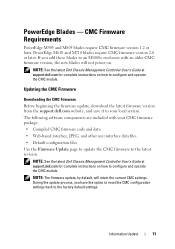
... 8 Port 8 Port 16 Port 16 B2 Port 8 Port 16 A2 Port 8 Port 16 Blade 6 A1 Integrated LOM1 Port 6 Integrated LOM2 Port 14 Mezz1_Fab_C Mezz2_Fab_B Mezz3_Fab_C Mezz4_Fab_B B1 Port 6 ...PowerEdge™ Blades - NOTE: OpenManage version 5.4.3 does not support PowerEdge M600 or M605 blades. The PowerEdge M610 and M710 blades require OpenManage systems management software version 6.0.1 or later. NOTE: OpenManage version 6.0.1 does not support PowerEdge M600, M605, M805, or M905 blades. 10 Information Update Dell™ OpenManage™ Version Requirements The PowerEdge M905 and M805 blades...
... 8 Port 8 Port 16 Port 16 B2 Port 8 Port 16 A2 Port 8 Port 16 Blade 6 A1 Integrated LOM1 Port 6 Integrated LOM2 Port 14 Mezz1_Fab_C Mezz2_Fab_B Mezz3_Fab_C Mezz4_Fab_B B1 Port 6 ...PowerEdge™ Blades - NOTE: OpenManage version 5.4.3 does not support PowerEdge M600 or M605 blades. The PowerEdge M610 and M710 blades require OpenManage systems management software version 6.0.1 or later. NOTE: OpenManage version 6.0.1 does not support PowerEdge M600, M605, M805, or M905 blades. 10 Information Update Dell™ OpenManage™ Version Requirements The PowerEdge M905 and M805 blades...
Information Update
Page 11
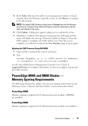
... the support.dell.com website, and save it to configure and operate the CMC module. PowerEdge Blades - The following software components are included with your local system. CMC Firmware Requirements PowerEdge M905 and M805 blades require CMC firmware version 1.2 or later. PowerEdge M610 and M710 blades require CMC ...settings back to configure and operate the CMC module. During the update process, you add these blades to the latest revision. NOTE: See the latest Dell Chassis Management Controller User's Guide at support.dell.com for complete instructions on . Information Update 11
... the support.dell.com website, and save it to configure and operate the CMC module. PowerEdge Blades - The following software components are included with your local system. CMC Firmware Requirements PowerEdge M905 and M805 blades require CMC firmware version 1.2 or later. PowerEdge M610 and M710 blades require CMC ...settings back to configure and operate the CMC module. During the update process, you add these blades to the latest revision. NOTE: See the latest Dell Chassis Management Controller User's Guide at support.dell.com for complete instructions on . Information Update 11
Information Update
Page 13
...console and log in. 2 Type: racadm fwupdate -g -u -a -d -m See the latest Dell Chassis Management Controller User's Guide at support.dell.com for complete instructions on your Hardware Owner's Manual and these blades' system information labels. Information Update 13 Once the reset is complete, you to confirm the...DIMMs) are installed. Keep different firmware revisions separated as the file name will display the message "Firmware Update in Progress." PowerEdge M905 and M805 Blades - 5 In the Value field, type the path on how to log in again. NOTE: The default CMC firmware image...
...console and log in. 2 Type: racadm fwupdate -g -u -a -d -m See the latest Dell Chassis Management Controller User's Guide at support.dell.com for complete instructions on your Hardware Owner's Manual and these blades' system information labels. Information Update 13 Once the reset is complete, you to confirm the...DIMMs) are installed. Keep different firmware revisions separated as the file name will display the message "Firmware Update in Progress." PowerEdge M905 and M805 Blades - 5 In the Value field, type the path on how to log in again. NOTE: The default CMC firmware image...

Information Update
Page 14
For detailed information on support.dell.com. New Mezzanine Cards Your blade now supports the following additional I/O modules: • Dell PowerConnect™ M8024 10 Gb Ethernet switch module • Mellanox M2401G DDR Infiniband switch module • Brocade M5424 FC8 switch module ... for Quad-Port Mezzanine Card" on page 8 for the support matrix. • Broadcom NetXExtreme II 5709 Quad Port Ethernet Mezzanine Card for M-Series Blades • Broadcom 57710 10 Gb Ethernet card • Emulex LPe1205-M FC8 card • ConnectX MDI QDR NOTE: CMC firmware version 1.3 is required...
For detailed information on support.dell.com. New Mezzanine Cards Your blade now supports the following additional I/O modules: • Dell PowerConnect™ M8024 10 Gb Ethernet switch module • Mellanox M2401G DDR Infiniband switch module • Brocade M5424 FC8 switch module ... for Quad-Port Mezzanine Card" on page 8 for the support matrix. • Broadcom NetXExtreme II 5709 Quad Port Ethernet Mezzanine Card for M-Series Blades • Broadcom 57710 10 Gb Ethernet card • Emulex LPe1205-M FC8 card • ConnectX MDI QDR NOTE: CMC firmware version 1.3 is required...

Information Update
Page 15
... Gb Ethernet module with three copper CX4 uplinks The modules can initially configure the switch using a terminal application. • Use the iKVM CMC console ("17th blade") and the connect switch-n CMC CLI command.
... Gb Ethernet module with three copper CX4 uplinks The modules can initially configure the switch using a terminal application. • Use the iKVM CMC console ("17th blade") and the connect switch-n CMC CLI command.

Information Update
Page 17
Mellanox M2401G Infiniband Switch I/O Module The Mellanox M2401G Infiniband switch I/O module includes 24 4x DDR Infiniband ports. Mellanox M2401G Infiniband Switch Module 1 2 3 4 5 1 Infiniband ports (8) 3 port activity indicators (8) 5 status/identification indicator 2 port link status indicators (8) 4 module power indicator Information Update 17 Figure 1-2. Eight ports are external uplink ports, while 16 internal ports provide connectivity to the blades in the enclosure.
Mellanox M2401G Infiniband Switch I/O Module The Mellanox M2401G Infiniband switch I/O module includes 24 4x DDR Infiniband ports. Mellanox M2401G Infiniband Switch Module 1 2 3 4 5 1 Infiniband ports (8) 3 port activity indicators (8) 5 status/identification indicator 2 port link status indicators (8) 4 module power indicator Information Update 17 Figure 1-2. Eight ports are external uplink ports, while 16 internal ports provide connectivity to the blades in the enclosure.

Information Update
Page 21
... contains data that the replacement hard drive is installed, the blade supports hot-plug drive removal and installation. • If less than the maximum number of the blade, each hard drive bay must be mixed within a blade. Ensure that you wish to maintain proper cooling airflow. Information... drive is installed and the blade is powered on, the hard drive automatically begins to four 2.5 inch SAS hard drives. • The PowerEdge M610, M600 and M605 blades support one or two 2.5- Updates on Hard Drive Installation • The PowerEdge M805 and M905 blades support one or two 2.5-inch...
... contains data that the replacement hard drive is installed, the blade supports hot-plug drive removal and installation. • If less than the maximum number of the blade, each hard drive bay must be mixed within a blade. Ensure that you wish to maintain proper cooling airflow. Information... drive is installed and the blade is powered on, the hard drive automatically begins to four 2.5 inch SAS hard drives. • The PowerEdge M610, M600 and M605 blades support one or two 2.5- Updates on Hard Drive Installation • The PowerEdge M805 and M905 blades support one or two 2.5-inch...

Information Update
Page 22
Carefully align the channel on the hard drive carrier with the appropriate drive slot on the blade. 3 Push the drive carrier into the slot until the handle makes contact with the blade. 4 Rotate the carrier handle to the closed position while pushing the carrier into the slot until it locks into the drive...
Carefully align the channel on the hard drive carrier with the appropriate drive slot on the blade. 3 Push the drive carrier into the slot until the handle makes contact with the blade. 4 Rotate the carrier handle to the closed position while pushing the carrier into the slot until it locks into the drive...


