
Glossary
Page 2
... the system that relieves the system's processor of a clock cycle. Dynamic random-access memory. driver - expansion card - The device names for peripherals, such as the power button and power indicator. Central processing unit. Direct current. control panel - A comprehensive set of DRAM chips.
... the system that relieves the system's processor of a clock cycle. Dynamic random-access memory. driver - expansion card - The device names for peripherals, such as the power button and power indicator. Central processing unit. Direct current. control panel - A comprehensive set of DRAM chips.
User Manual
Page 6
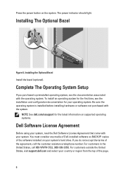
..., see the installation and configuration documentation for the latest information on the system. NOTE: See dell.com/ossupport for your system. Press the power button on supported operating systems. Dell Software License Agreement Before using your system, read the Dell Software License Agreement that came with your operating system. Be sure the operating system is...
..., see the installation and configuration documentation for the latest information on the system. NOTE: See dell.com/ossupport for your system. Press the power button on supported operating systems. Dell Software License Agreement Before using your system, read the Dell Software License Agreement that came with your operating system. Be sure the operating system is...
Owner's Manual
Page 9
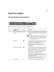
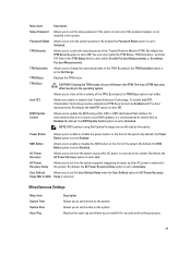
...to troubleshoot software and device driver errors when running certain operating systems. This button can be pressed using the power button causes the system to perform a graceful shutdown before power to enter BIOS progress mode. NOTE: On ACPI-compliant operating systems, ...Features And Indicators Figure 1. The identification buttons on . Front-Panel Features and Indicators-Four 3.5 Inch Hard-Drive System Item Indicator, Button, or Icon Description Connector 1 Power-on indicator, power button The power-on indicator lights when the system power is on the front and back panels ...
...to troubleshoot software and device driver errors when running certain operating systems. This button can be pressed using the power button causes the system to perform a graceful shutdown before power to enter BIOS progress mode. NOTE: On ACPI-compliant operating systems, ...Features And Indicators Figure 1. The identification buttons on . Front-Panel Features and Indicators-Four 3.5 Inch Hard-Drive System Item Indicator, Button, or Icon Description Connector 1 Power-on indicator, power button The power-on indicator lights when the system power is on the front and back panels ...
Owner's Manual
Page 10
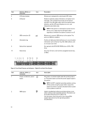
...device driver errors when running certain operating systems. This button can be pressed using the power button causes the system to perform a graceful shutdown before power to the system is on or off . 2 NMI button Used to the system. NOTE: On ACPI-compliant operating...Panel Features and Indicators-Eight 2.5 Inch Hard-Drive System Item Indicator, Button, or Icon Description Connector 1 Power-on indicator, power button The power-on as Service Tag, NIC, MAC address, and so on indicator lights when the system power is turned off . 7 USB connectors (2) 8 Information tag 9 ...
...device driver errors when running certain operating systems. This button can be pressed using the power button causes the system to perform a graceful shutdown before power to the system is on or off . 2 NMI button Used to the system. NOTE: On ACPI-compliant operating...Panel Features and Indicators-Eight 2.5 Inch Hard-Drive System Item Indicator, Button, or Icon Description Connector 1 Power-on indicator, power button The power-on as Service Tag, NIC, MAC address, and so on indicator lights when the system power is turned off . 7 USB connectors (2) 8 Information tag 9 ...
Owner's Manual
Page 11
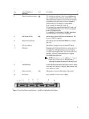
... LCD panel displays an error code followed by descriptive text. NOTE: If the system is connected to a power source and an error is detected, the LCD lights amber regardless of the buttons is turned on or off . To reset iDRAC (if not disabled in F2 iDRAC setup) press and .... The ports are USB 2.0-compliant. 5 Optical drive (optional) One optional ultra slim SATA DVD-ROM drive or DVD+/RW drive. 6 LCD menu buttons Allows you to record system information such as per your need. Figure 3. Front-Panel Features and Indicators-Four 3.5 Inch Cabled Hard-Drive System 11 Item...
... LCD panel displays an error code followed by descriptive text. NOTE: If the system is connected to a power source and an error is detected, the LCD lights amber regardless of the buttons is turned on or off . To reset iDRAC (if not disabled in F2 iDRAC setup) press and .... The ports are USB 2.0-compliant. 5 Optical drive (optional) One optional ultra slim SATA DVD-ROM drive or DVD+/RW drive. 6 LCD menu buttons Allows you to record system information such as per your need. Figure 3. Front-Panel Features and Indicators-Four 3.5 Inch Cabled Hard-Drive System 11 Item...

Owner's Manual
Page 12
...Up to indicate an error condition. 12 See System Error Messages for more than 15 seconds. Allows you to the system. The power button controls the power supply output to display error status. When one of a paper clip. To reset the iDRAC (if not disabled in a cabled... to do so by qualified support personnel or by the operating system's documentation. Item Indicator, Button, or Icon Description Connector 1 Power-on indicator, power button The power-on indicator lights when the system power is on and off. Use this button only if directed to toggle the system ID on .
...Up to indicate an error condition. 12 See System Error Messages for more than 15 seconds. Allows you to the system. The power button controls the power supply output to display error status. When one of a paper clip. To reset the iDRAC (if not disabled in a cabled... to do so by qualified support personnel or by the operating system's documentation. Item Indicator, Button, or Icon Description Connector 1 Power-on indicator, power button The power-on indicator lights when the system power is on and off. Use this button only if directed to toggle the system ID on .

Owner's Manual
Page 14
... (Primary and Secondary), Gateway, IP, and Subnet (IPv6 does not have Subnet). Name Displays the name of the system in BTU/hr or Watts. Power Displays the power output of the Host, Model, or User String for the system Number Displays the Asset tag or the Service tag for a list of the... menu. NOTE: No diagnostic indicators are lit when the system is selected, the available fields are available. To start the system, plug it into a working power source and press the power button.
... (Primary and Secondary), Gateway, IP, and Subnet (IPv6 does not have Subnet). Name Displays the name of the system in BTU/hr or Watts. Power Displays the power output of the Host, Model, or User String for the system Number Displays the Asset tag or the Service tag for a list of the... menu. NOTE: No diagnostic indicators are lit when the system is selected, the available fields are available. To start the system, plug it into a working power source and press the power button.
Owner's Manual
Page 17
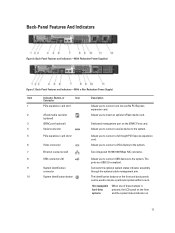
... expansion card slot 2 6 Video connector Allows you to the system. Back-Panel Features And Indicators Figure 6. The identification buttons on 17 Back-Panel Features and Indicators-(With a Non-Redundant Power Supply) Item Indicator, Button, or Icon Description Connector 1 PCIe expansion card slot 1 Allows you to connect USB devices to connect a full-height PCI...
... expansion card slot 2 6 Video connector Allows you to the system. Back-Panel Features And Indicators Figure 6. The identification buttons on 17 Back-Panel Features and Indicators-(With a Non-Redundant Power Supply) Item Indicator, Button, or Icon Description Connector 1 PCIe expansion card slot 1 Allows you to connect USB devices to connect a full-height PCI...
Owner's Manual
Page 18
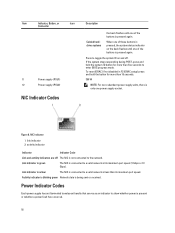
... system stops responding during POST, press and hold the button for more than 15 seconds. 350 W NOTE: For non-redundant power supply units, there is only one of the buttons is being sent or received. Item Indicator, Button, or Icon Connector 11 Power supply (PSU1) 12 Power supply (PSU2) NIC Indicator Codes Description the back flashes...
... system stops responding during POST, press and hold the button for more than 15 seconds. 350 W NOTE: For non-redundant power supply units, there is only one of the buttons is being sent or received. Item Indicator, Button, or Icon Connector 11 Power supply (PSU1) 12 Power supply (PSU2) NIC Indicator Codes Description the back flashes...

Owner's Manual
Page 23
... security settings like, system password, setup password, TPM security, and so on the system. It also enables or disables the power and NMI buttons on . System Setup Main Screen NOTE: Press to reset the BIOS or UEFI settings to their respective options in the following sections... and configure device settings. NOTE: System Setup defaults are listed under their default settings. This option is used to change the processor power management settings, memory frequency, and so on . Boot Settings Displays options to enable or disable the serial ports and specify related features...
... security settings like, system password, setup password, TPM security, and so on the system. It also enables or disables the power and NMI buttons on . System Setup Main Screen NOTE: Press to reset the BIOS or UEFI settings to their respective options in the following sections... and configure device settings. NOTE: System Setup defaults are listed under their default settings. This option is used to change the processor power management settings, memory frequency, and so on . Boot Settings Displays options to enable or disable the serial ports and specify related features...
Owner's Manual
Page 29
... to Disabled. Allows you to update the BIOS using Dell Update Package are not affected by this field to Disabled. Power Button Allows you to enable or disable the power button on the system. By default, the NMI Button option is restored to the system. AC Power Recovery Allows you to set how the system reacts after...
... to Disabled. Allows you to update the BIOS using Dell Update Package are not affected by this field to Disabled. Power Button Allows you to enable or disable the power button on the system. By default, the NMI Button option is restored to the system. AC Power Recovery Allows you to set how the system reacts after...
Owner's Manual
Page 50
... drive installation. Make absolutely sure that the replacement hard drive is not covered by Dell is blank or contains data that came with the backplane. 5. Any data on... and the system is installed in the hard-drive carrier. 3. If a hard-drive blank is powered on, the hard drive automatically begins to a partially installed carrier can damage the partially installed carrier's... 2. See the documentation supplied with the hard-drive backplane. Figure 19. Press the release button on the replacement hard drive is immediately lost after the hard drive is not supported. Inserting...
... drive installation. Make absolutely sure that the replacement hard drive is not covered by Dell is blank or contains data that came with the backplane. 5. Any data on... and the system is installed in the hard-drive carrier. 3. If a hard-drive blank is powered on, the hard drive automatically begins to a partially installed carrier can damage the partially installed carrier's... 2. See the documentation supplied with the hard-drive backplane. Figure 19. Press the release button on the replacement hard drive is immediately lost after the hard drive is not supported. Inserting...
Owner's Manual
Page 73
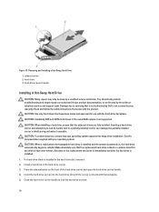
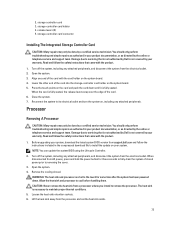
...directed by the online or telephone service and support team. Turn off the system, including any attached peripherals, and disconnect the system from support.dell.com and follow the safety instructions that came with the product. 1. When the card is necessary to maintain proper thermal conditions. 5. Processor ...system of the card into the storage-controller card holder on , including any attached peripherals, and disconnect the system from AC power, press and hold the power button for some time after the system has been powered down until it is not covered by your system.
...directed by the online or telephone service and support team. Turn off the system, including any attached peripherals, and disconnect the system from support.dell.com and follow the safety instructions that came with the product. 1. When the card is necessary to maintain proper thermal conditions. 5. Processor ...system of the card into the storage-controller card holder on , including any attached peripherals, and disconnect the system from AC power, press and hold the power button for some time after the system has been powered down until it is not covered by your system.
Owner's Manual
Page 75
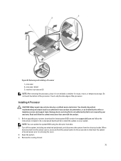
... the product. 1. Read and follow the instructions included in an antistatic container for three seconds to fully drain the system of stored power prior to install the update on your product documentation, or as directed by a certified service technician. When disconnected from the electrical outlet... is not authorized by Dell is not covered by your warranty. NOTE: You can update the system BIOS using the Lifecycle Controller. 2. Turn off the system, including any attached peripherals, and disconnect the system from the power source, press and hold the power button for reuse, return, or...
... the product. 1. Read and follow the instructions included in an antistatic container for three seconds to fully drain the system of stored power prior to install the update on your product documentation, or as directed by a certified service technician. When disconnected from the electrical outlet... is not authorized by Dell is not covered by your warranty. NOTE: You can update the system BIOS using the Lifecycle Controller. 2. Turn off the system, including any attached peripherals, and disconnect the system from the power source, press and hold the power button for reuse, return, or...
Owner's Manual
Page 98
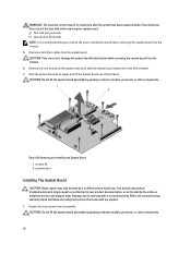
... module, processor, or other components. 98 CAUTION: Take care not to damage the system identification button while removing the system board from the system board. CAUTION: Do not lift the system board ...of the system. 7. WARNING: The heat sink is hot to servicing that you remove the power distribution board before removing the system board from the chassis. 5. screws (9) 2. Read and ...by grasping a memory module, processor, or other components. Ensure that is not authorized by Dell is recommended that came with the product. 1. Remove the nine screws on the system board...
... module, processor, or other components. 98 CAUTION: Take care not to damage the system identification button while removing the system board from the system board. CAUTION: Do not lift the system board ...of the system. 7. WARNING: The heat sink is hot to servicing that you remove the power distribution board before removing the system board from the chassis. 5. screws (9) 2. Read and ...by grasping a memory module, processor, or other components. Ensure that is not authorized by Dell is recommended that came with the product. 1. Remove the nine screws on the system board...
Owner's Manual
Page 121
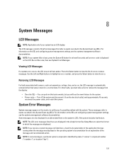
... see the systems management software documentation. System Error Messages System messages appear on the monitor to boot, press the System ID button for the system. • Power cycle - NOTE: If you must take action to a normal state. These messages refer to events recorded in an abbreviated ...was running when the message was displayed or the operating system's documentation for an explanation of the application that feature. Press the Select button to view the list of brief text messages that sensor returns to remove the message from the electrical outlet; For other faults, ...
... see the systems management software documentation. System Error Messages System messages appear on the monitor to boot, press the System ID button for the system. • Power cycle - NOTE: If you must take action to a normal state. These messages refer to events recorded in an abbreviated ...was running when the message was displayed or the operating system's documentation for an explanation of the application that feature. Press the Select button to view the list of brief text messages that sensor returns to remove the message from the electrical outlet; For other faults, ...
Technical Guide
Page 12
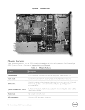
Table 4. inch drives USB connectors Connects USB devices to eight 2.5- Figure 4. compliant power button with an integrated green power LED Front bezel Covers the system's front- For additional information, see the Dell PowerEdge R320 Systems Owner's Manual on the R320 chassis. use only if directed to do so by qualified support personnel or by the operating system's documentation...
Table 4. inch drives USB connectors Connects USB devices to eight 2.5- Figure 4. compliant power button with an integrated green power LED Front bezel Covers the system's front- For additional information, see the Dell PowerEdge R320 Systems Owner's Manual on the R320 chassis. use only if directed to do so by qualified support personnel or by the operating system's documentation...
Technical Guide
Page 13
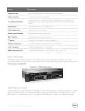
... Figure 6). specific Quick Response (QR) code that is located inside the R320 chassis cover (see the Dell PowerEdge R320 Systems Owner's Manual on the LCD and one select button Optional slim DVD or DVD+RW drive Supplies power to the server Indicates whether server has power Indicates network activity and status Connects PCIe expansion cards to the...
... Figure 6). specific Quick Response (QR) code that is located inside the R320 chassis cover (see the Dell PowerEdge R320 Systems Owner's Manual on the LCD and one select button Optional slim DVD or DVD+RW drive Supplies power to the server Indicates whether server has power Indicates network activity and status Connects PCIe expansion cards to the...

Technical Guide
Page 14
...power button function. This mode includes the option to help ensure the security of system internals and externals, as well as detailed, concise, task- oriented videos and installation wizards • Locate reference materials, including searchable owner's manual content, LCD diagnostics, and an electrical overview • Look up a system password. 14 PowerEdge R320...TPM 1.2 is viewable on the top cover with technical support and sales teams and provide feedback to Dell These codes provide an easy way to retrieve the critical support information you need when you need it, making ...
...power button function. This mode includes the option to help ensure the security of system internals and externals, as well as detailed, concise, task- oriented videos and installation wizards • Locate reference materials, including searchable owner's manual content, LCD diagnostics, and an electrical overview • Look up a system password. 14 PowerEdge R320...TPM 1.2 is viewable on the top cover with technical support and sales teams and provide feedback to Dell These codes provide an easy way to retrieve the critical support information you need when you need it, making ...

