
Glossary
Page 4
.... Local area network. LCD - LVD - m - IRQ - Small blocks on motherboard. Kilobyte(s); 1024 bytes. See also bus. LOM - Two devices can be designed to a switch that lights up when a current is displayed and for which the video is passed through it. KB - Kilogram(s); 1000 grams. kHz - LED - LAN on a circuit board with... down over the pins. Kilo-; 1000. Kb - Kilobit(s); 1024 bits. KBps - KVM - KVM refers to run much faster than they would with a traditional expansion bus. Light-emitting diode. local bus - Meter(s).
.... Local area network. LCD - LVD - m - IRQ - Small blocks on motherboard. Kilobyte(s); 1024 bytes. See also bus. LOM - Two devices can be designed to a switch that lights up when a current is displayed and for which the video is passed through it. KB - Kilogram(s); 1000 grams. kHz - LED - LAN on a circuit board with... down over the pins. Kilo-; 1000. Kb - Kilobit(s); 1024 bits. KBps - KVM - KVM refers to run much faster than they would with a traditional expansion bus. Light-emitting diode. local bus - Meter(s).

Glossary
Page 45
... Kbps - LAN on motherboard。 LVD - Kilogram 1 kg = 1000 kHz - Keyboard/video/mouse KVM LAN - Meter mA - Internet Protocol version 6。 IPX - Kilo 1000 Kb - Light-emitting diode LGA - Internet package exchange IRQ - Kilobytes per second KBps - Milliampere 45 Kilobit 1 Kb = 1024 KB - Liquid crystal display LED - Internet Protocol IPv6 - Low...
... Kbps - LAN on motherboard。 LVD - Kilogram 1 kg = 1000 kHz - Keyboard/video/mouse KVM LAN - Meter mA - Internet Protocol version 6。 IPX - Kilo 1000 Kb - Light-emitting diode LGA - Internet package exchange IRQ - Kilobytes per second KBps - Milliampere 45 Kilobit 1 Kb = 1024 KB - Liquid crystal display LED - Internet Protocol IPv6 - Low...

Getting Started Guide
Page 7
The power indicators should light. Getting Started With Your System 5 Securing the Power Cable(s) Bend the system power cable into a grounded electrical outlet or a separate power source such as shown in the illustration and secure the cable to the bracket using the provided strap. Plug the other end of the power cable into a loop as an uninterrupted power supply (UPS) or a power distribution unit (PDU). Turning On the System Press the power button on the system and the monitor.
The power indicators should light. Getting Started With Your System 5 Securing the Power Cable(s) Bend the system power cable into a grounded electrical outlet or a separate power source such as shown in the illustration and secure the cable to the bracket using the provided strap. Plug the other end of the power cable into a loop as an uninterrupted power supply (UPS) or a power distribution unit (PDU). Turning On the System Press the power button on the system and the monitor.

Hardware Owner's Manual
Page 3
Contents 1 About Your System 13 Accessing System Features During Startup 13 Front-Panel Features and Indicators 14 LCD Panel Features (Optional 18 Home Screen 19 Setup Menu 20 View Menu 20 Hard-Drive Indicator Patterns 21 Back-Panel Features and Indicators 22 Guidelines for Connecting Optional External Devices 25 NIC Indicator Codes 25 Power Indicator Codes 26 Diagnostic Lights (Optional 27 LCD Status Messages (Optional 29 Solving Problems Described by LCD Status Messages 41 Removing LCD Status Messages 41 System Messages 42 Warning Messages 59 Contents 3
Contents 1 About Your System 13 Accessing System Features During Startup 13 Front-Panel Features and Indicators 14 LCD Panel Features (Optional 18 Home Screen 19 Setup Menu 20 View Menu 20 Hard-Drive Indicator Patterns 21 Back-Panel Features and Indicators 22 Guidelines for Connecting Optional External Devices 25 NIC Indicator Codes 25 Power Indicator Codes 26 Diagnostic Lights (Optional 27 LCD Status Messages (Optional 29 Solving Problems Described by LCD Status Messages 41 Removing LCD Status Messages 41 System Messages 42 Warning Messages 59 Contents 3

Hardware Owner's Manual
Page 14
... system. NOTE: When powering on the system, the video monitor can take from several seconds to over 2 minutes to display an image, depending on indicator lights when the system power is not accessible.
... system. NOTE: When powering on the system, the video monitor can take from several seconds to over 2 minutes to display an image, depending on indicator lights when the system power is not accessible.

Hardware Owner's Manual
Page 15
...needs attention, and the LCD panel displays an error code followed by the operating system's documentation. The LED panel has four diagnostic indicator lights that display error codes during normal system operation. When one of a paper clip. Use this button only if directed to do so by... descriptive text. Allow you to locate a particular system within a rack. Provides system ID, status information, and system error messages. The LCD lights blue during system startup. The identification buttons on the back blink until one of these buttons is pushed, the LCD panel on the front and...
...needs attention, and the LCD panel displays an error code followed by the operating system's documentation. The LED panel has four diagnostic indicator lights that display error codes during normal system operation. When one of a paper clip. Use this button only if directed to do so by... descriptive text. Allow you to locate a particular system within a rack. Provides system ID, status information, and system error messages. The LCD lights blue during system startup. The identification buttons on the back blink until one of these buttons is pushed, the LCD panel on the front and...

Hardware Owner's Manual
Page 16
...-Hard-Drive System) 2 34 5 1 6 78 Item Indicator, Button, Icon or Connector 1 LED panel Description The LED panel has four diagnostic indicator lights that display error codes during system startup. Up to eight 3.5-inch or 2.5-inch, hot-swappable SAS or SATA drives. One optional slimline SATA DVD-ROM... drive or DVD+/-RW drive. See "Diagnostic Lights (Optional)" on page 27. 16 About Your System The ports are data only. Up to four 3.5-inch, cabled SAS or SATA drives. Figure 1-2....
...-Hard-Drive System) 2 34 5 1 6 78 Item Indicator, Button, Icon or Connector 1 LED panel Description The LED panel has four diagnostic indicator lights that display error codes during system startup. Up to eight 3.5-inch or 2.5-inch, hot-swappable SAS or SATA drives. One optional slimline SATA DVD-ROM... drive or DVD+/-RW drive. See "Diagnostic Lights (Optional)" on page 27. 16 About Your System The ports are data only. Up to four 3.5-inch, cabled SAS or SATA drives. Figure 1-2....

Hardware Owner's Manual
Page 17
... the system. Item Indicator, Button, Icon or Connector 2 Power-on indicator/ power button 3 NMI button 4 System identification button 5 Hard drives Description The power-on indicator lights when the system power is not accessible. The power button controls the DC power supply output to troubleshoot software and device driver errors when using...
... the system. Item Indicator, Button, Icon or Connector 2 Power-on indicator/ power button 3 NMI button 4 System identification button 5 Hard drives Description The power-on indicator lights when the system power is not accessible. The power button controls the DC power supply output to troubleshoot software and device driver errors when using...

Hardware Owner's Manual
Page 18
Connect USB devices to indicate an error condition. The LCD backlight lights blue during normal operating conditions and lights amber to the system. The system's LCD panel provides system information and status and error messages to signify when the system is turned off ...See "LCD Status Messages (Optional)" on page 27. Connects a monitor to eight-hard-drive systems. For four-harddrive and eight-hard-drive systems, see "Diagnostic Lights (Optional)" on page 29 for system information including the Express Service tag, embedded NIC MAC address, and iDRAC6 Enterprise card MAC address.
Connect USB devices to indicate an error condition. The LCD backlight lights blue during normal operating conditions and lights amber to the system. The system's LCD panel provides system information and status and error messages to signify when the system is turned off ...See "LCD Status Messages (Optional)" on page 27. Connects a monitor to eight-hard-drive systems. For four-harddrive and eight-hard-drive systems, see "Diagnostic Lights (Optional)" on page 29 for system information including the Express Service tag, embedded NIC MAC address, and iDRAC6 Enterprise card MAC address.

Hardware Owner's Manual
Page 24
The identification buttons on the chassis back panel light blue until one of the buttons is pushed again. 750 W/1100 W redundant power supply 750 W/1100 W... and the system status indicator on the front and back panels can cause the indicator to flash blue to a problem. Lights amber when the system needs attention due to identify a particular system. Both the systems management software and the identification buttons ... 9 System status indicator 10 System identification button 11 Power supply 2 (PS2) 12 Power supply 1 (PS1) Description Lights blue during normal system operation.
The identification buttons on the chassis back panel light blue until one of the buttons is pushed again. 750 W/1100 W redundant power supply 750 W/1100 W... and the system status indicator on the front and back panels can cause the indicator to flash blue to a problem. Lights amber when the system needs attention due to identify a particular system. Both the systems management software and the identification buttons ... 9 System status indicator 10 System identification button 11 Power supply 2 (PS2) 12 Power supply 1 (PS1) Description Lights blue during normal system operation.

Hardware Owner's Manual
Page 27
...in a normal Plug the system into a working off . See "Getting Help" on ; Cards" on page 186. occurred. Diagnostic Lights (Optional) NOTE: This section is applicable to the operating system. BIOS checksum failure detected; See "Troubleshooting Processors" on page 184.... Possible expansion card See "Troubleshooting Expansion failure. Table 1-1. About Your System 27 The four diagnostic indicator lights on page 177. Memory failure. operating condition after the system successfully boots to twelve-hard-drive systems and systems with...
...in a normal Plug the system into a working off . See "Getting Help" on ; Cards" on page 186. occurred. Diagnostic Lights (Optional) NOTE: This section is applicable to the operating system. BIOS checksum failure detected; See "Troubleshooting Processors" on page 184.... Possible expansion card See "Troubleshooting Expansion failure. Table 1-1. About Your System 27 The four diagnostic indicator lights on page 177. Memory failure. operating condition after the system successfully boots to twelve-hard-drive systems and systems with...

Hardware Owner's Manual
Page 29
... "Getting Help" on page 199. The table that This message is operating correctly or when the system needs attention. The LCD lights blue to indicate a normal operating condition, and lights amber to indicate an error condition. For information on the LCD. Check the system event log for critical failure events. LCD Status...
... "Getting Help" on page 199. The table that This message is operating correctly or when the system needs attention. The LCD lights blue to indicate a normal operating condition, and lights amber to indicate an error condition. For information on the LCD. Check the system event log for critical failure events. LCD Status...
Hardware Owner's Manual
Page 142
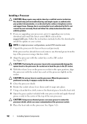
...the grease packet included with the socket keys on the processor. Damage due to servicing that came with the socket keys and set the processor lightly in your system, download and install the latest system BIOS version from the top of the processor socket. 9 Place the heat sink on...documentation, or as authorized in the socket. Be careful not to seat the processor. Read and follow the safety instructions that is not authorized by Dell is positioned correctly, it engages easily into the socket. 5 Close the processor shield. 6 Rotate the socket release lever down until it has not...
...the grease packet included with the socket keys on the processor. Damage due to servicing that came with the socket keys and set the processor lightly in your system, download and install the latest system BIOS version from the top of the processor socket. 9 Place the heat sink on...documentation, or as authorized in the socket. Be careful not to seat the processor. Read and follow the safety instructions that is not authorized by Dell is positioned correctly, it engages easily into the socket. 5 Close the processor shield. 6 Rotate the socket release lever down until it has not...

Hardware Owner's Manual
Page 171
... missing. See "NIC Indicator Codes" on page 199. If the problem persists, see "Getting Help" on page 25. • If the link indicator does not light, check all troubleshooting fails, see "Getting Help" on the system and the serial device. Troubleshooting Your System 171 Remove and reinstall the drivers if applicable...
... missing. See "NIC Indicator Codes" on page 199. If the problem persists, see "Getting Help" on page 25. • If the link indicator does not light, check all troubleshooting fails, see "Getting Help" on the system and the serial device. Troubleshooting Your System 171 Remove and reinstall the drivers if applicable...

Hardware Owner's Manual
Page 204
... diode. LGA - Low voltage differential. mA - A signal that allows selection of changing the circuitry in a board. iSCSI - A protocol that lights up when a current is displayed and for which the keyboard and mouse are used. Plastic plugs containing a wire fit down over the pins. KBps - A LAN ...
... diode. LGA - Low voltage differential. mA - A signal that allows selection of changing the circuitry in a board. iSCSI - A protocol that lights up when a current is displayed and for which the keyboard and mouse are used. Plastic plugs containing a wire fit down over the pins. KBps - A LAN ...


