
Glossary
Page 2
... the system by transferring data on the system board. Dual in memory modules that contains indicators and controls, such as 208.77.188.166. See also memory module. DRAM - driver - Error checking and correction. ESM - expansion card - The device names for peripherals, such as a NIC or SCSI adapter, that plugs into IP addresses, such as the power button and power indicator. A chip or expansion card that allows the operating system or some specialized...
... the system by transferring data on the system board. Dual in memory modules that contains indicators and controls, such as 208.77.188.166. See also memory module. DRAM - driver - Error checking and correction. ESM - expansion card - The device names for peripherals, such as a NIC or SCSI adapter, that plugs into IP addresses, such as the power button and power indicator. A chip or expansion card that allows the operating system or some specialized...
Glossary
Page 3
... an output device. host adapter - Input/output. Integrated Dell Remote Access Controller. InfiniBand - The file system structure used primarily with high-speed peripherals. FTP - Gb - A video mode that can be programmed and reprogrammed using a software utility. hot-plug - A keyboard is an input device, and a monitor is usually rounded to organize and keep track of processors with networked storage devices. expansion-card connector - A connector on and running. F - File allocation table. The Microsoft® Windows® operating systems can...
... an output device. host adapter - Input/output. Integrated Dell Remote Access Controller. InfiniBand - The file system structure used primarily with high-speed peripherals. FTP - Gb - A video mode that can be programmed and reprogrammed using a software utility. hot-plug - A keyboard is an input device, and a monitor is usually rounded to organize and keep track of processors with networked storage devices. expansion-card connector - A connector on and running. F - File allocation table. The Microsoft® Windows® operating systems can...

Glossary
Page 7
... system's boot routine and the POST. Serial-attached SCSI. service tag - A bar code label on the system used to connect a modem to the system BIOS and then display an error message on motherboard. A registered DDR3 memory module. Read-only memory. ROMB - SAS - Second(s). A legacy I /O bus interface with a 9-pin connector that transfers data one that contains information supplementing or updating the product's documentation. SMART - See also mirroring and striping. Any information stored in ROM code. SCSI - Random-access memory. The...
... system's boot routine and the POST. Serial-attached SCSI. service tag - A bar code label on the system used to connect a modem to the system BIOS and then display an error message on motherboard. A registered DDR3 memory module. Read-only memory. ROMB - SAS - Second(s). A legacy I /O bus interface with a 9-pin connector that transfers data one that contains information supplementing or updating the product's documentation. SMART - See also mirroring and striping. Any information stored in ROM code. SCSI - Random-access memory. The...

Glossary
Page 8
... port - USB memory key - See memory key. 8 Symmetric multiprocessing. See also guarding, mirroring, and RAID. Super video graphics array. system board - TCP/IP - An unregistered (unbuffered) DDR3 memory module. A port on each disk. USB - SNMP - A standard interface that allows a network manager to configure your system's integral components, such as password protection. The amount of an electrical failure. system configuration information - Because the System Setup program is stored in NVRAM, any settings remain in memory that automatically supplies power to enable...
... port - USB memory key - See memory key. 8 Symmetric multiprocessing. See also guarding, mirroring, and RAID. Super video graphics array. system board - TCP/IP - An unregistered (unbuffered) DDR3 memory module. A port on each disk. USB - SNMP - A standard interface that allows a network manager to configure your system's integral components, such as password protection. The amount of an electrical failure. system configuration information - Because the System Setup program is stored in NVRAM, any settings remain in memory that automatically supplies power to enable...
Owner's Manual
Page 11
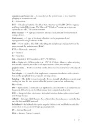
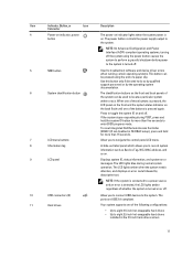
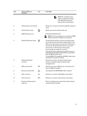
... reset integrated Dell Remote Access Controller (iDRAC) (if not disabled in the 3.5 inch hard-drive carriers 11 Displays system ID, status information, and system error messages. Allow you to connect USB devices to locate a particular system within a rack. NOTE: On Advanced Configuration and Power Interface (ACPI)-compliant operating systems, turning off . 5 NMI button 6 System identification button 7 LCD menu buttons 8 Information tag 9 LCD panel Used to troubleshoot software and device driver errors when running certain operating systems. This button can be used...
... reset integrated Dell Remote Access Controller (iDRAC) (if not disabled in the 3.5 inch hard-drive carriers 11 Displays system ID, status information, and system error messages. Allow you to connect USB devices to locate a particular system within a rack. NOTE: On Advanced Configuration and Power Interface (ACPI)-compliant operating systems, turning off . 5 NMI button 6 System identification button 7 LCD menu buttons 8 Information tag 9 LCD panel Used to troubleshoot software and device driver errors when running certain operating systems. This button can be used...
Owner's Manual
Page 15
... supported only on or off. 7 Video connector 8 USB connectors (2) 9 Optical drive 1 (optional) 10 Optical drive 2 (optional) Allows you to connect USB devices to record system information such as Service Tag, NIC, MAC address, and so on. 6 LCD panel Displays system ID, status information, and system error messages. Item Indicator, Button, or Icon Description Connector To reset iDRAC (if not disabled in 3.5 inch hard-drive carriers. • Up to two optional SATA DVD-ROM drive or DVD+/-RW drive. The LCD lights amber...
... supported only on or off. 7 Video connector 8 USB connectors (2) 9 Optical drive 1 (optional) 10 Optical drive 2 (optional) Allows you to connect USB devices to record system information such as Service Tag, NIC, MAC address, and so on. 6 LCD panel Displays system ID, status information, and system error messages. Item Indicator, Button, or Icon Description Connector To reset iDRAC (if not disabled in 3.5 inch hard-drive carriers. • Up to two optional SATA DVD-ROM drive or DVD+/-RW drive. The LCD lights amber...
Owner's Manual
Page 21
...a rack. To reset iDRAC (if not disabled in systems with cabled hard drives and systems with an x8 backplane. 2 PCIe expansion card slots (6) 3 vFlash media card slot 4 iDRAC7 Enterprise port 5 System identification button 6 System identification connector 7 USB connectors (6) 8 Ethernet connectors (2) 9 Video connector 10 Serial connector 11 External cooling-fan power cable slot Allows you to connect the optional system status indicator assembly through the optional cable management arm. Two integrated 10/100/1000 Mbps NIC connectors. Allows you to connect USB devices...
...a rack. To reset iDRAC (if not disabled in systems with cabled hard drives and systems with an x8 backplane. 2 PCIe expansion card slots (6) 3 vFlash media card slot 4 iDRAC7 Enterprise port 5 System identification button 6 System identification connector 7 USB connectors (6) 8 Ethernet connectors (2) 9 Video connector 10 Serial connector 11 External cooling-fan power cable slot Allows you to connect the optional system status indicator assembly through the optional cable management arm. Two integrated 10/100/1000 Mbps NIC connectors. Allows you to connect USB devices...
Owner's Manual
Page 25
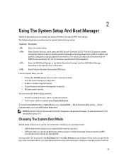
...Change the NVRAM settings after you add or remove hardware • View the system hardware configuration • Enable or disable integrated devices • Set performance and power management thresholds • Manage system security You can access the System Setup using a graphical user interface. Enters the BIOS Boot Manager or the Unified Extensible Firmware Interface (UEFI) Boot Manager, depending on Unified Extensible Firmware Interface (UEFI) specifications that 25 Choosing The System Boot Mode System Setup enables you to install your system hardware and specify BIOS...
...Change the NVRAM settings after you add or remove hardware • View the system hardware configuration • Enable or disable integrated devices • Set performance and power management thresholds • Manage system security You can access the System Setup using a graphical user interface. Enters the BIOS Boot Manager or the Unified Extensible Firmware Interface (UEFI) Boot Manager, depending on Unified Extensible Firmware Interface (UEFI) specifications that 25 Choosing The System Boot Mode System Setup enables you to install your system hardware and specify BIOS...
Owner's Manual
Page 27
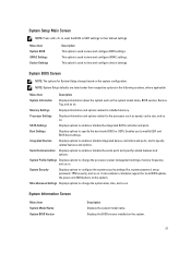
...local BIOS update, the power and NMI buttons on . Enables you to view and configure BIOS settings. System Security Displays options to the processor such as the system model name, BIOS version, Service Tag, and so on the system. Processor Settings Displays information and options related to configure the system security settings like, system password, setup password, TPM security, and so on . SATA Settings Displays options to specify the boot mode (BIOS or UEFI). Boot Settings Displays options to enable or disable the integrated SATA controller and ports. System...
...local BIOS update, the power and NMI buttons on . Enables you to view and configure BIOS settings. System Security Displays options to the processor such as the system model name, BIOS version, Service Tag, and so on the system. Processor Settings Displays information and options related to configure the system security settings like, system password, setup password, TPM security, and so on . SATA Settings Displays options to specify the boot mode (BIOS or UEFI). Boot Settings Displays options to enable or disable the integrated SATA controller and ports. System...
Owner's Manual
Page 31
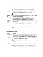
... PCIe cards installed in the BIOS. By default, the SR-IOV Global Enable option is installed on both the Option ROM and UEFI driver are disabled. If the slot is disabled, both SD cards. Slot Disablement Allows you to enable or disable the integrated network cards 1 and 2. Serial Port Address Allows you to Mirror. To use console redirection by SOL, configure the same port address for serial devices. NOTE: This option is displayed only if IDSDM is set to enable or disable the Embedded Video Controller...
... PCIe cards installed in the BIOS. By default, the SR-IOV Global Enable option is installed on both the Option ROM and UEFI driver are disabled. If the slot is disabled, both SD cards. Slot Disablement Allows you to enable or disable the integrated network cards 1 and 2. Serial Port Address Allows you to Mirror. To use console redirection by SOL, configure the same port address for serial devices. NOTE: This option is displayed only if IDSDM is set to enable or disable the Embedded Video Controller...
Owner's Manual
Page 36
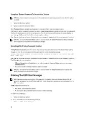
..., the error message is displayed until the correct password is Enabled, enter the correct setup password before modifying most of unsuccessful password attempts: System Halted! Number of the System Setup options. Entering The UEFI Boot Manager NOTE: Operating systems must be 64-bit UEFI-compatible (for example, Microsoft Windows Server 2008 x64 version) to re-enter your password and press . Turn on or reboot your system from the BIOS boot mode. You have assigned a setup password, the...
..., the error message is displayed until the correct password is Enabled, enter the correct setup password before modifying most of unsuccessful password attempts: System Halted! Number of the System Setup options. Entering The UEFI Boot Manager NOTE: Operating systems must be 64-bit UEFI-compatible (for example, Microsoft Windows Server 2008 x64 version) to re-enter your password and press . Turn on or reboot your system from the BIOS boot mode. You have assigned a setup password, the...
Owner's Manual
Page 38
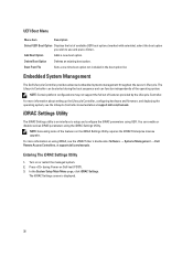
...information about setting up the Lifecycle Controller, configuring hardware and firmware, and deploying the operating system, see the iDRAC7 User's Guide under Software → Systems Management → Dell Remote Access Controllers, at support.dell.com/manuals. Add Boot Option Adds a new boot option. Turn on using the iDRAC Settings Utility. In the System Setup Main Menu page, click iDRAC Settings. Boot From File Sets a one-time boot option not included in the boot option list. UEFI Boot Menu Menu Item Description Select UEFI Boot Option Displays the list of the...
...information about setting up the Lifecycle Controller, configuring hardware and firmware, and deploying the operating system, see the iDRAC7 User's Guide under Software → Systems Management → Dell Remote Access Controllers, at support.dell.com/manuals. Add Boot Option Adds a new boot option. Turn on using the iDRAC Settings Utility. In the System Setup Main Menu page, click iDRAC Settings. Boot From File Sets a one-time boot option not included in the boot option list. UEFI Boot Menu Menu Item Description Select UEFI Boot Option Displays the list of the...
Owner's Manual
Page 52
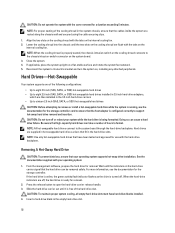
... to support hot-swap hard drive removal and insertion. Removing A Hot-Swap Hard Drive CAUTION: To prevent data loss, ensure that the host adapter is running, see the documentation for use with the hard-drive backplane. See the documentation supplied with the tabs on the cooling shroud are routed along the chassis wall and secured using the cable securing clips. 1. From the management software, prepare the hard drive for the storage controller card to eight 2.5 inch (SAS, SATA, or SSD) hot-swappable hard drives installed...
... to support hot-swap hard drive removal and insertion. Removing A Hot-Swap Hard Drive CAUTION: To prevent data loss, ensure that the host adapter is running, see the documentation for use with the hard-drive backplane. See the documentation supplied with the tabs on the cooling shroud are routed along the chassis wall and secured using the cable securing clips. 1. From the management software, prepare the hard drive for the storage controller card to eight 2.5 inch (SAS, SATA, or SSD) hot-swappable hard drives installed...
Owner's Manual
Page 94
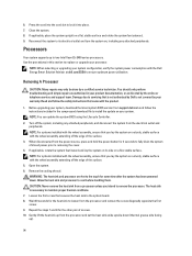
... heat sink to servicing that you intend to remove the processor. 6. Read and follow the instructions included in the compressed download file to ensure optimum power utilization. NOTE: You can update the system BIOS using the Lifecycle Controller. 2. Turn off the system, including any attached peripherals. WARNING: The heat sink and processor are hot to two Intel Xeon E5-2400 series processors. Before upgrading your warranty. NOTE: For systems installed...
... heat sink to servicing that you intend to remove the processor. 6. Read and follow the instructions included in the compressed download file to ensure optimum power utilization. NOTE: You can update the system BIOS using the Lifecycle Controller. 2. Turn off the system, including any attached peripherals. WARNING: The heat sink and processor are hot to two Intel Xeon E5-2400 series processors. Before upgrading your warranty. NOTE: For systems installed...
Owner's Manual
Page 121
... perform troubleshooting and simple repairs as directed by a certified service technician. Safety Instructions NOTE: For specific caution statements and procedures, see the safety instructions that shipped with hot-swappable hard drives are rackable. Preparing A System For Conversion From Tower Mode To Rack Mode You require the following precautions for rack mode • #2 Phillips screwdriver 1. NOTE: For systems installed with three screws each • VGA module • Control panel for...
... perform troubleshooting and simple repairs as directed by a certified service technician. Safety Instructions NOTE: For specific caution statements and procedures, see the safety instructions that shipped with hot-swappable hard drives are rackable. Preparing A System For Conversion From Tower Mode To Rack Mode You require the following precautions for rack mode • #2 Phillips screwdriver 1. NOTE: For systems installed with three screws each • VGA module • Control panel for...

Owner's Manual
Page 126
... light, check all troubleshooting fails, see Getting Help. Remove and reinstall the drivers if applicable. Ensure that the NIC ports are enabled on the network are all network cables are bound. See the documentation for available diagnostic tests. 2. If all cable connections. - You should only perform troubleshooting and simple repairs as authorized in the System Setup options. Open the system. 126 If your keyboard is not accessible, reset the NVRAM_CLR jumper inside your product documentation...
... light, check all troubleshooting fails, see Getting Help. Remove and reinstall the drivers if applicable. Ensure that the NIC ports are enabled on the network are all network cables are bound. See the documentation for available diagnostic tests. 2. If all cable connections. - You should only perform troubleshooting and simple repairs as authorized in the System Setup options. Open the system. 126 If your keyboard is not accessible, reset the NVRAM_CLR jumper inside your product documentation...
Owner's Manual
Page 131
... files on the hard drive. Troubleshooting An Optical Or Tape Drive CAUTION: Many repairs may only be done by a certified service technician. Ensure that the interface cable is enabled. 2. Read and follow the safety instructions that the integrated SATA controller and the drive's SATA port are enabled. 3. Remove the front bezel. 7. Ensure that a power cable is set to Mirror Mode in step 4 through step 7 to its electrical outlet and turn the system...
... files on the hard drive. Troubleshooting An Optical Or Tape Drive CAUTION: Many repairs may only be done by a certified service technician. Ensure that the interface cable is enabled. 2. Read and follow the safety instructions that the integrated SATA controller and the drive's SATA port are enabled. 3. Remove the front bezel. 7. Ensure that a power cable is set to Mirror Mode in step 4 through step 7 to its electrical outlet and turn the system...
Owner's Manual
Page 135
... to run diagnostic tests on the systems in the system does not operate properly, running system diagnostics is run from the Dell Lifecycle Controller. You can use the graphical user interface (GUI) or the command line interface (CLI) to test only your system, run diagnostic tests on chassis and storage components such as Enhanced Pre-boot System Assessment (ePSA) diagnostics. For information about the failed device(s) • View status messages that inform you are completed successfully • View error messages...
... to run diagnostic tests on the systems in the system does not operate properly, running system diagnostics is run from the Dell Lifecycle Controller. You can use the graphical user interface (GUI) or the command line interface (CLI) to test only your system, run diagnostic tests on chassis and storage components such as Enhanced Pre-boot System Assessment (ePSA) diagnostics. For information about the failed device(s) • View status messages that inform you are completed successfully • View error messages...
Owner's Manual
Page 139
... connector (Cable management arm) USB connectors USB connectors NIC connectors Serial connector/video connector Chassis intrusion switch connector Processor 2 Power connector Power connector Memory module sockets Processor socket External cooling fan connector Backplane connector System battery connector Internal USB connector Internal cooling fan connector Power distribution board connector SATA_F connector for optical disk drive 2 or tape backup unit SATA_E connector for optical disk drive 1 or, tape backup unit in use. The password jumper enables these password features or disables...
... connector (Cable management arm) USB connectors USB connectors NIC connectors Serial connector/video connector Chassis intrusion switch connector Processor 2 Power connector Power connector Memory module sockets Processor socket External cooling fan connector Backplane connector System battery connector Internal USB connector Internal cooling fan connector Power distribution board connector SATA_F connector for optical disk drive 2 or tape backup unit SATA_E connector for optical disk drive 1 or, tape backup unit in use. The password jumper enables these password features or disables...
Owner's Manual
Page 157
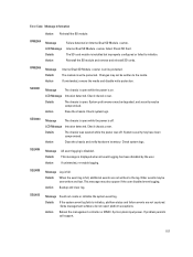
... Failure detected on . The SD card module is open . The module is displayed when all event logging has been disabled by the user. Changes may not be overwritten and lost. Check system logs. Action Backup and clear log. SEC0031 Message The chassis is installed but improperly configured or failed to initialize, platform status and failure events are not written to the media. SEC0033 Message The chassis is open while the power is on Internal Dual SD Module . LCD Message Intrusion detected. This message...
... Failure detected on . The SD card module is open . The module is displayed when all event logging has been disabled by the user. Changes may not be overwritten and lost. Check system logs. Action Backup and clear log. SEC0031 Message The chassis is installed but improperly configured or failed to initialize, platform status and failure events are not written to the media. SEC0033 Message The chassis is open while the power is on Internal Dual SD Module . LCD Message Intrusion detected. This message...


